Introduction
The performance demands on plasma facing components (PFCs), first wall, and blanket systems of future fusion power are beyond the capability of current materials, which is one of the reasons that the United States National Academy of Engineering has ranked the quest for fusion as one of the top grand challenges for engineering in the 21st century.1 The fusion plasma in the international tokamak experimental reactor (ITER) and projected future power plants will be at a temperature of roughly 100 million K (see the Raj et al. article in MRS Bulletin April 2008 issue), which corresponds to an average kinetic energy for the hydrogen isotopes of roughly 10 keV.Reference Wesson2–Reference Roth and Garcia-Rosales4 Hence, particles escaping the plasma encounter the plasma facing materials and first wall structural materials, where they deposit their kinetic energy in the form of atomic displacements and deposited thermal energy. Moreover, the deuterium (D)–D and D–tritium (T) reactions produce neutrons, T, and He nuclei with energies up to 14 MeV. In tokamak plasma confinement, the plasma should be fully confined, but in practice, significant leakage of the plasma occurs in the divertor at the bottom of the reactor as well as on the edges.
The fusion energy plasma environment presents numerous inherently multiscale computational grand challenges at the extreme of high-performance computing. For example, consideration of the edge, or boundary region where the plasma meets the material surface, leads to the identification of three coupled spatial regions that involve critical scientific issues for fusion power. These regions consist of (1) the edge and scrape off layer region of the plasma, (2) the near-surface material response to extreme thermal and particle fluxes under the influence of, and feedback to, the plasma sheath, and (3) the structural materials response to an intense, 14 MeV peaked neutron spectrum, which produces very high concentrations of transmuted elements within the bulk of the material through nuclear (n,p) and (n,α) reactions in which neutrons (n) are absorbed and protons (p) or alpha (α) particles (e.g., helium nuclei) are emitted from the nucleus, which transmutes the nucleus to a different element containing one or two fewer protons, respectively. These interlinked, plasma-materials interactions (PMI) are critical scientific issues for fusion power and affect (1) the PFC lifetime due to erosion processes during both steady-state and transient operation, (2) bulk plasma performance through plasma contamination by eroded materials, (3) tritium management, including co-deposition of T and D in eroded/redeposited material, and, perhaps more importantly, (4) the fusion performance of the core plasma. Likewise, the performance of bulk structural and breeding blanket materials in a challenging degradation environment with large time-varying stresses, corrosive chemical environments, and large fluxes of 14-MeV peaked fusion neutrons affects the thermal and power management of the fusion reactor and the overall tritium balance and controls the operating/replacement lifetime of the vacuum vessel.
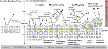
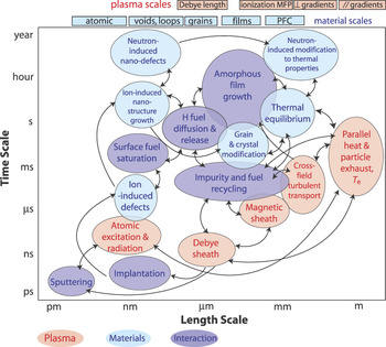
Gaining understanding and predictive capabilities in this critical area will require addressing, simultaneously, complex and diverse physics occurring over a wide range of lengths (angstroms to meters) and times (femtoseconds to days), as illustrated schematically in Figures 1 and 2. Figure 1 demonstrates a range of known phenomena that govern the response of the materials surface to plasma interaction. While vastly different physical scales exist for the surface (on the scale of nanometers) and plasma processes (on the scale of millimeters), the plasma and material surface are strongly coupled to each other, mediated by an electrostatic and magnetic sheath. As but one example, the high probability (>90%) of prompt local ionization and re-deposition of sputtered material atoms means that the surface material in contact with the plasma is itself a plasma-deposited surface, not the original ordered surface. Likewise, the recycling of hydrogenic plasma fuel is self-regulated through processes involving the near-surface fuel transport in the material and the ionization of neutral species that enter the plasma. Also the intense radiation environment of ions, neutrons, and photons ensures that the material structure and properties are modified and dynamically coupled to the PMI processes at extreme thermal fluxes that may exceed 20 MW/m2, and thereby induce significant temperature gradients in the near-surface region.
Schematic illustration of the complex, synergistic, and inherently multiscale surface interactions occurring at the material surface in a realistic magnetic fusion plasma environment. H, hydrogen; D, deuterium; T, tritium; PFC, plasma facing component; γ, gamma ray.

Graphical representation of the multiple time and length scales involved in the inherently coupled processes and phenomena that dictate plasma materials interactions in the boundary plasma region of magnetic fusion devices. Processes occurring within the plasma are denoted in light red, while those in the near-surface and bulk materials are in light blue, and the important plasma—materials interactions—are identified in light purple. PFC, plasma facing component; T e, electron temperature; and MFP, mean free path.

Within the structures, the exposure to high-energy radiation severely damages the microstructure of materials by violently displacing atoms from their lattice sites many times and creating damaging concentrations of helium and hydrogen, in addition to other transmuted elements. The resulting microstructural evolutions cause profound macroscopic property changes that severely degrade the performance and lifetime limits of first wall components.Reference Bloom5–Reference Muroga, Gasparotto and Zinkle10 As reviewed by Zinkle,Reference Zinkle9 the observed property changes of irradiated materials depend on the irradiation temperature and other environmental variables and have been called the “five scourges of irradiation.” These degradation phenomena include irradiation hardening and embrittlement, phase and dimensional instability, and He embrittlement.
The effect of irradiation on materials microstructure and properties is a classic example of an inherently multiscale phenomenon. Pertinent processes range from the atomic nucleus to structural component length scales, spanning in excess of 10 orders of magnitude, while time scales bridge more than 22 orders of magnitude.Reference Odette, Wirth, Bacon and Ghoniem11 Further, a wide range of variables controls the mix of nano/microstructural features formed and the corresponding degradation of physical and mechanical properties. The most important variables include the initial material microstructure, the thermal-mechanical loads, and irradiation history. Yet, radiation damage and helium effects are believed to be the overarching concerns for first wall and breeding blanket structures.Reference Bloom5–Reference Muroga, Gasparotto and Zinkle10 While many of the controlling radiation damage processes and kinetics are known, quantitative details regarding the interactions among evolving species and, indeed, even the transport, trapping/de-trapping, and annihilation mechanisms of small defect-impurity clusters, as well as the defect cluster interactions with transmutant products, including He and H, remain to be established.
The multiscale nature of the plasma-materials interaction is illustrated in Figure 2, where the different color symbols represent physical phenomena occurring in the plasma (light red spheres), the bulk materials (light blue spheres), and the near-surface interaction region (light purple spheres). The smaller time and length scales correspond to individual ion implantation and sputtering processes, which occur at or near the material surface, in addition to a range of ionization and recombination processes of the sputtered neutrals and ions in the near-surface sheath and neutron-induced displacement cascade and nuclear transmutation events, which serve as the source term for radiation damage processes within the structural material. At intermediate length and time scales, a wealth of physical processes are initiated, including diffusion of the now implanted ionic/neutral species, the possibility of chemical sputtering processes at the surface, the formation of gas bubbles, surface diffusion driving surface topology changes, and phonon scattering by radiation defects that reduces the thermal conductivity of the material, as well as the nucleation of radiation damage defect clusters. At longer length and time scales, additional phenomena, such as long-range material transport in the plasma, re-deposition of initially sputtered surface atoms, amorphous film growth, and hydrogenic species diffusion and permeation into the bulk material become important, as do irradiation-induced void and bubble formation and the partitioning of radiation-induced defects to dislocations and extended defects that can drive irradiation creep or stress relaxation processes. This broad palette of physical phenomena will require development not only of detailed physics models and computational strategies at each of these scales, but also of algorithms and methods to strongly couple them in a way that can be robustly validated. While present research is confined to each of these scales, or pioneering ways to couple two or more of them, the current approaches already push the state-of-the-art in technique and available computational power. Therefore, simulations spanning multiple scales are needed for ITER and DEMO (DEMOnstration Power Plant) and will require extreme-scale computing platforms and integrated physics and computer science advances.
The remainder of this article will present two examples where high-performance computing has provided improved insight into materials degradation in the fusion environment. The first investigates the prompt chemical sputtering that occurs during the exposure of graphite to hydrogenic plasmas and demonstrates aspects of the material erosion and hydrogenic inventory challenges in PMI. The second example combines experimental investigation and computational multiscale materials modeling to investigate helium-point defect interactions in iron, which demonstrates the structural materials challenges of high levels of (n,α) transmutations in the fusion energy environment.
Swift chemical sputtering by low-energy ions and tritium retention
A particularly intriguing and important aspect of the plasma wall interactions has been the issue of the low-energy erosion of carbon. Numerous experiments have shown that any carbon-based first wall material in the bottom part of the reactor (the divertor) erodes with high yields at energies clearly below the physical sputtering threshold.Reference Yamashina and Hino12, Reference Horn, Schenk, Biener, Winter, Lutterloh, Wittmann and Kuppers13 While this anomalous erosion can, at high temperatures, be understood by hydrogen-induced formation of volatile species that desorb by thermal activation,Reference Kuppers14 the effect does not show any temperature dependence between liquid nitrogen and room temperature,Reference de Juan Pardo, Balden, Cieciwa, Garcia-Rosales and Roth15 showing that a thermally activated mechanism cannot be the full explanation.
Molecular dynamics computer simulations have shown that the erosion can be explained by a special type of chemical sputtering, where the incoming energetic ion enters between two carbon atoms, forcing them apart if its kinetic energy is low enough that it spends a substantial amount of time between the atoms.Reference Salonen, Nordlund, Keinonen and Wu16–Reference Krasheninnikov, Nordlund, Salonen, Keinonen and Wu18 If one of the carbon atoms is only loosely bound to the surface, this can cause sputtering of it, along with any hydrogens that may be bound to it. Also, sputtering of larger molecules is possible.Reference Salonen, Nordlund, Keinonen and Wu17 Several aspects of this “swift chemical” sputtering of carbon have been examined by computer simulations, such as its angular dependence,Reference Marian, Zepeda-Ruiz, Couto, Bringa, Gilmer, Stangeby and Rognlien19 effect of electronically excited states,Reference Krstic, Reinhold and Stuart20 co-bombardment with plasma impurities,Reference Maya, von Toussaint and Hopf21 and the effect of sample structure.Reference Alman and Ruzic22 The simulated and experimental sputtering yields also have been found to be in good agreement with each other.Reference Salonen23, Reference Krstic, Reinhold and Stuart24
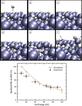
The basic mechanism behind swift chemical sputtering is not specific to carbon, raising the natural question of whether the process may occur in other kinds of plasmas and materials as well. As its essence is breaking of chemical bonds by a moderate (few eV) kinetic energy, allowing ions to enter between covalently bonded atoms, it is natural to assume it might occur in other kinds of covalent materials. The effect has been reported for Si and WC as well.Reference Nordlund, Salonen, Krasheninnikov and Keinonen25, Reference Traskelin, Juslin, Erhart and Nordlund26 For metals, chemical sputtering is generally not expected to occur,Reference Johnson and Schou27 and as the ITER design for the D+T phase has been recently switched to include only Be and W as first-wall materials,Reference Wesson2 one might expect that the issue of chemical sputtering under fusion reactor conditions would be moot. However, a recent combination of molecular dynamics simulations and experiments showed, quite surprisingly, that pure Be metal also can erode chemically in the form of BeH molecules during high-dose H bombardment,Reference Bjorkas, Vörtler, Nordlund, Nishijima and Doerner28 as shown in Figure 3. Although the yields for this process are fortunately much lower than those for carbon-based materials,Reference Bjorkas, Vörtler, Nordlund, Nishijima and Doerner28 the observation shows that even in a purely metallic tokamak, intriguing and complex physicochemical plasma wall radiation damage mechanisms are an issue to consider.
(a)–(f) A sequence of molecular dynamics simulation results showing the chemical sputtering of Be during low-energy deuterium (D) ion irradiation. (a), (b), and (c) show the impact of the 10 eV D ion between Be atoms (large blue spheres), while (d) and (e) demonstrate the local rearrangement and rotation that breaks several Be–Be bonds prior to the chemical sputtering of a BeD molecule in (f). The lower part shows a comparison of simulated and experimental Be sputtering fractions as a function of the incoming D energy. Data are from Reference 24.

Another very serious aspect of the plasma wall radiation damage in fusion reactors is tritium retention. If any carbon is present in the reactor, it will erode in the form of small CH radicals and molecules, which, in turn, tend to stick in other parts of the reactor, forming both soft and hard carbon films.Reference Jacob29 These can have very large T contents in a form that is hard to remove, and this, in fact, has been the major reason why the revised ITER design projects will not use carbon-based materials in the first wall during D+T operation. However, a fully metallic reactor design also has T retention issues. Both fusion neutrons and tritonsReference Kurki-Suonio, Hynönen, Ahlgren, Nordlund, Sugiyama and Dux30 can produce damage deep in W divertor components. Since hydrogen is highly mobile in W,Reference Frauenfelder31 any T impacting on W can migrate deep into it but also can get trapped in vacancies or other kinds of radiation damage introduced by the energetic particle irradiations.Reference Ahlgren, Heinola, Vainonen-Ahlgren, Likonen and Keinonen32 The elevated temperatures at the ITER (and future power plant) divertors may alleviate thermal release of the T, but further study will be needed to resolve whether this effect alone is sufficient to avoid excessive T inventory buildup in metal-based tokamaks.
Helium point defect interactions in bulk iron
A particularly challenging aspect of the fusion neutron irradiation environment for structural materials is the large 14-MeV peaked neutron spectrum, which will induce on the order of 10 atomic parts per million of He through (n,α) reactions per displacement per atom (10 appm He/dpa). The threshold (n,α) reactions do not occur at sufficient rates in fission neutron irradiation facilities, making the experimental study of helium point defect interactions and helium bubble nucleation very challenging, although a number of techniques are available to study the problem in micron-thick layers.Reference Yamamoto, Odette, Miao, Hoelzer, Bentley, Hashimoto, Tanigawa and Kurtz33 The combination of experimental measurements of the thermal desorption of He from materials following ion implantation, in addition to computational modeling of the desorption spectra and release mechanisms, is expected to provide insight into the physical mechanisms of He defect interactions that control the desorption flux. Such insight is critical for accurately modeling the nucleation of He bubbles in ferritic/martensitic alloys operating in fusion neutron environments and, in particular, assessing the conditions leading to He bubble formation on grain boundaries, which is known to dramatically decrease fracture toughness and creep rupture lifetimes.Reference Trinkaus34, Reference Ullmaier35 Additional details regarding the experimental thermal desorption measurements and the spatially dependent cluster dynamics methods used to model He desorption are presented in Reference 36.
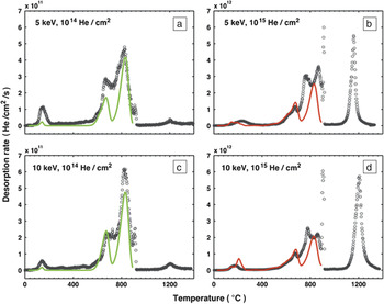
Figure 4 presents experimentally obtained thermal He desorption data (open symbols) and predicted desorption spectra (solid lines) from single crystalline iron specimens, which were implanted with either 5 or 10 keV He ions to a fluence of 10Reference Kuppers14 or 1015 He/cm2, during thermal annealing with a constant heating rate of 1°C/second. The nominal He implantation flux was ~1011He/(cm2s). The data clearly show two well-separated major desorption groups within the bcc temperature range (up to 912°C, where a very sharp release peak exists that marks the structural phase transformation of iron from the body-centered cubic alpha phase to the fcc gamma phase): Group I below ~300ºC and Group II from ~550ºC to 912ºC. Further, increasing implantation fluence from 1014 to 1015 He/cm2 greatly increases the fraction of retained He that does not desorb until ~1200ºC. This phase transformation at 912°C and the corresponding sharp, non-first-order He desorption release peak provide a precise temperature calibration to our experimental measurements.
Experimental (open symbols) and predicted (solid lines) He desorption spectra in single crystal iron following implantation of (a) 5 keV, 1014 He/cm2; (b) 5 keV, 1015 He/cm2; (c) 10 keV, 1014 He/cm2; and (d) 10 keV, 1015 He/cm2. The experimental data were obtained with a constant heating rate of 1°C/s. In general, the model desorption spectra match the experimental data fairly well at the lower fluence.Reference Xu and Wirth36

The solid lines in Figure 4 are the predicted He desorption from a model that incorporates both temporally and spatially dependent He and point defect diffusion, trapping, and de-trapping kinetics during the implantation process and thermal annealing. The model results in Figure 4 represent the modeled desorption spectra with the best overall agreement with the experiments obtained so far using a single set of optimized parameters for the vacancy migration energy and the binding energy of very small helium–vacancy clusters containing one to three vacancies and up to five helium atoms. The selection of optimized parameters was guided based on input from ab initio electronic structure calculations of He point defect interactions in iron,Reference Fu and Willaime37, Reference Seletskaia, Osetsky, Stoller and Stocks38 as well as from molecular dynamics and cluster dynamics simulation results.Reference Morishita, Sugano, Wirth and de la Rubia39, Reference Ortiz, Caturla, Fu and Willaime40 It can be seen that quite similarly to the experimental observations, the model predicts two well-separated major desorption groups within the bcc temperature range, one below 300ºC and the other above 550ºC. Moreover, the main peak positions are also reproduced fairly well by the model. On the other hand, the model requires further improvement or optimization to better reproduce the intensities of the desorption peaks as well as the splitting of the strongest peak (around 800ºC) within the bcc range for the two higher fluence (1015 He/cm2) specimens. While determining the binding energy of small clusters is important to provide an accurate model prediction of the observed desorption peaks, these small clusters are not the sole players controlling desorption. In fact, each desorption peak involves the collective action of a distribution of cluster sizes.
At lower implantation fluences, the He-V clusters are rather small, mostly consisting of less than 10 He and less than 10 V. The composition distribution is rather diffuse in both He and V directions and is confined by a boundary corresponding to a He/V ratio a bit larger than 2. As the temperature increases to 350ºC, the smallest He2V cluster concentration is significantly reduced as relatively low binding energy He is de-trapped. Larger clusters with relatively low He/V ratios become unstable with respect to V binding and thus emit vacancies, while those with relatively high He/V ratios become unstable and emit He. The de-trapped He atoms partly diffuse to the surface where they desorb and are partly re-trapped by other clusters during their diffusional migration. At higher temperatures, the He vacancy cluster distribution is mostly associated with small to intermediate clusters (<15 vacancies) containing an equal number of He atoms. The majority of these clusters dissolve by about 900°C.
The higher fluence specimens follow quite a different evolution path. At 100°C (or after the implantation), the cluster distribution is rather diffuse, predominately He rich, and dominated by clusters that contain between three and seven vacancies and five to 12 helium atoms. With increasing temperature to about 350°C, the diffuse cluster distribution rapidly evolves into a line in the phase space with a He/V ratio of ~1.6 by 350°C. The de-trapping and emission of both He and V occur as the temperature continues to rise, and by ~600°C, the He/V ratio becomes close to 1. At this point, the smaller He vacancy clusters, including He3V2 and a few others such as He4V3 and He5V4, all begin to dissociate, releasing a large number of He and V atoms. The increase in both He and V concentrations in the matrix leads to the formation of larger He-V clusters. This quickly results in the fast growth of larger clusters with He/V ratios of about 1, while the small clusters (below He5V5) continue to dissociate. These predictions can be verified through transmission electron microscopy and/or positron annihilation spectroscopy measurements, as well as implantation and thermal desorption measurements in other irradiation conditions, which will provide a validated set of He defect kinetic energies that can be used for extrapolating to fusion neutron irradiation conditions.
Challenges and research directions
The fusion energy plasma environment presents numerous inherently multiscale computational grand challenges at the extreme of high-performance computing. In particular, the plasma materials interaction involve a number of complex, interdependent processes occurring over a wide range of length and time scales that affect the bulk plasma performance and the operating lifetime of the plasma facing components (PFCs). Likewise, the structural materials for the vacuum vessel and breeding blanket must face an incredibly extreme environment with heat and particle fluxes, large and time-varying thermomechanical stresses, corrosive coolants, and severe fluxes of neutrons peaked at 14 MeV. The neutron irradiation effects are believed to be overarching, and while numerous articles have described the multiscale materials modeling challenges associated with irradiation effects on structural materials, the additional component of transmutant elements through threshold (n,p) and (n,α) reactions makes this an even more daunting challenge.
The continual improvement in high-performance computing is a key ingredient in improving knowledge of fusion materials performance required to develop predictive performance models and improved PFC and structural materials. At the smallest scales, electronic structure calculations are needed to inform the development of interatomic interactions of complex, multicomponent W-C-He-H-Be mixed materials in the near-surface region of PFCs and many-elemental structural steels, including nanocomposite variants. Molecular dynamics and accelerated dynamics techniques are also well suited for utilizing high-performance computing capabilities to discover the kinetic mechanisms governing surface and microstructural evolution. Over the longer-term, modeling techniques need to be developed to bridge the time scales inherent in plasma-materials interaction response and microstructural evolution in structural materials, as well as to strongly couple them in a way that can be robustly validated.
Acknowledgments
B.D.W. and D.X. acknowledge support by the U.S. Department of Energy, Office of Fusion Energy Sciences under grant DE-FG02-04GR54750 and as part of the multi-institution PSI Plasma Science Center under grant DE-SC0002209. D.G.W. acknowledges support by the U.S. Department of Energy, Office of Fusion Energy Sciences as part of the multi-institution PSI Plasma Science Center under grant DE-SC0002209. K.N. acknowledges useful discussions with Dr. T. Kurki-Suonio on energetics of particles in fusion plasma.