Introduction
Historically, characterization of the structure and chemistry of intact solid–liquid interfaces at the nanoscale has been challenging. However, this is critical for understanding the dominant nanoscale mechanisms in electrochemistry, energy storage, corrosion, and material surface functionalization. Recent progress in instrumentation has allowed solid–liquid interfaces to be studied at the nanoscale in both the static cryogenic state and the dynamic liquid state; the cryogenic state allows detailed and site-specific chemical and structural mapping, while the liquid state yields in situ imaging of dynamic processes.
Even though cryogenic electron microscopy (cryo-EM) and liquid-phase electron microscopy (LPEM) have become well established over the past decade, cryogenic specimen preparation procedures that were initially designed for immobilizing biological samples in a thin layer of vitreous iceReference Dubochet and Lepault1–Reference Varriano‐Marston, Gordon, Davis and Hutchinson7 were not directly applicable to many materials science explorations. To adapt cryo-EM for characterization of intact solid–liquid interfaces that are often present in the physical sciences, new advances in cryogenic sample preparation such as cryogenic focused ion beam (cryo-FIB) milling were required to enable buried interfaces to be revealed within large samples or devices.Reference Choudhury, Wan, Al Sadat, Tu, Lau, Zachman, Kourkoutis and Archer8–Reference Zachman, Tu, Choudhury, Archer and Kourkoutis13
The key advancement that enabled characterization of these buried interfaces by high-resolution techniques such as atom probe tomography (APT) or transmission electron microscopy (TEM) was the development of a cryo-FIB liftout technique.Reference Schreiber, Perea, Ryan, Evans and Vienna11,Reference Zachman, Asenath-Smith, Estroff and Kourkoutis12,Reference Antoniou, Graham, Hartfield and Amador14–Reference Rubino, Akhtar, Melin, Searle, Spellward and Leifer17 These sample preparation tools enable extraction and thinning of buried solid–liquid interfaces from devices such as batteries, which were previously inaccessible to techniques such as TEM and APT in an intact state. These cryogenic characterization methods complement in situ imaging with LPEM,Reference Chee, Pratt, Hattar, Duquette, Ross and Hull18–Reference Schilling, Janssen, Zaluzec and Burke28 which requires a more limited sample geometry, but allows dynamic processes to be observed in real time. The combination of these two will therefore be impactful for gaining a better understanding of the fundamental mechanisms behind processes at solid–liquid interfaces.
Cryo-FIB
High-quality specimen preparation is critical for high-resolution characterization of a material system. Until recently, lack of an appropriate technique for creating high-quality, intact solid–liquid interface samples from large systems was the limiting factor in high-resolution characterization of these structures. Traditional FIB was developed to enable milling of specimens by a focused ion beam (generally a Ga+ beam) to engineer nanostructures into specific morphologies and section bulk materials for cross-sectional imaging of features below the specimen surface. FIB is typically conducted with a dual-beam instrument that is also equipped with a scanning electron microscope column, which allows researchers to site-specifically identify features of interest and subsequently extract and thin them into electron-transparent lamellae. However, because FIB samples must be maintained in a high vacuum and the process of ion and electron bombardment during FIB processing is known to physically and chemically alter sensitive samples, liquids and biological materials were largely excluded from FIB processing in the past. However, the addition of a cryogenic specimen stage within the high vacuum environment of the FIB has enabled a number of these limitations to be overcome.Reference Heymann, Hayles, Gestmann, Giannuzzi, Lich and Subramaniam29–Reference Mulders32
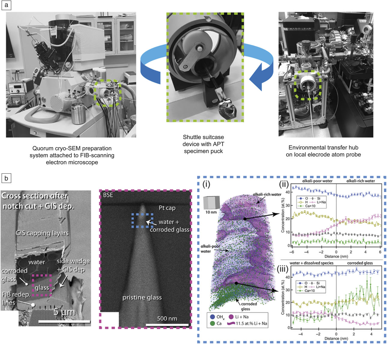
To prepare specimens by cryo-FIB, a combination of ex situ sample freezing and post-freeze processing using a cryogenic sample preparation station is employed. Freezing of a sample is typically accomplished by plunging into a liquid cryogen such as ethane or nitrogen slush, with temperatures near that of liquid nitrogen (77 K), flash-freezing the sample and preventing crystallization of liquids present if a sufficient cooling rate is achieved. A suitcase device is then used to enable an environmentally protected transfer of specimens to the cryo-FIB, as well as to the atom probe once specimens are prepared (Figure 1a). A cryogenic sample preparation station attached to the cryo-FIB allows electrical surface conductivity to be enhanced before insertion into the FIB chamber by applying a sputter-coated conductive film (e.g., Pt). For samples that include frozen water, features such as cellular morphology at the frozen sample surface can also be enhanced by in situ freeze fracturing or controlled sublimation of ice using a temperature-controlled stage heater. The sample is then transferred from the preparation chamber to the FIB stage via the shuttle suitcase device transfer rod. During sample processing and manipulation within the FIB, the sample remains frozen at near-LN2 temperatures, protected from atmospheric exposure, and frost deposition by high vacuum conditions.
Environmentally protected specimen transfer between cryogenic focused ion beam (cryo-FIB)/scanning electron microscope (SEM) and atom probe tomography (APT) tool enables tomographic analysis of a water–liquid interface in a corroded glass material. (a) Photograph of the modified cryo-FIB/SEM specimen preparation system and environmental transfer hub attached to the LEAP atom probe at Pacific Northwest National Laboratory. (Middle) A shuttle suitcase device enables environmentally protected transfer of specimens between the cryo-FIB/SEM where specimens are prepared, and (right) a modified LEAP tool for APT analysis. (b) Cryogenic sample preparation and APT analysis of corroded glass. (Left) Cryo-FIB cross-sectional SEM image of a mounted specimen; note the corroded glass layer flanked on either side by the corroding solid water (as ice) and pristine glass. (Middle) APT needle specimen showing targeted water–solid interface (purple dashed boxes). (Right) (i) Three-dimensional (3D) APT atom point-cloud map of targeted water–solid interface within the needle specimen (blue dashed boxes). A purple-colored isoconcentration surface representing 11.5 at.% Li + Na delineates the alkali-rich water, alkali-poor water, and the corroded glass, which is indicated by the presence of Ca. Respective one-dimensional composition profiles across the (ii) alkali-rich–alkali-poor interface in water reveals partitioning of dissolved alkali ions in the water ice and (iii) water–corroded glass region maps, where the composition across the liquid–solid interface is indicated by the Ca distribution, which has relatively low solubility in water. Note that although the partitioning of the alkali elements in the water ice may be an artifact of the freezing process, requiring application of alternative freezing methods (e.g., high-pressure freezing), the result is the first reported atom-by-atom mapping of a liquid–solid interface. The gray 3D cube with side lengths of 10 nm in (i) provides spatial scale to the 3D composition map.Reference Schreiber, Perea, Ryan, Evans and Vienna11 Note: GIS, gas injection system; BSE, backscattered electron.

The specimen stage in the FIB is typically cooled either passively through a conductive copper rod attached to a small external LN2 dewar or actively by flowing nitrogen gas through a heat exchanger in an external LN2 dewar, and subsequently through gas lines to the stage. This maintains the sample in a solid state and reduces the effects of electron and ion beam heating during imaging and milling. Currently, the maximum specimen size that can be inserted into the instrument is roughly 1 cmReference Dubochet and McDowall3, which can limit preparation of TEM and APT specimens from samples larger than this. Additionally, until recently, cryogenic stage designs have prevented large angle rotations, which can limit site-specific targeting of specimen features. With no anticontamination device present, the low sample temperature would result in unwanted condensation of water ice and other contaminants onto the sample surface from the vacuum. Consequently, a cold trap is positioned above the sample and held at a lower temperature to minimize condensation of such contaminants on the cryogenic sample.Reference Zachman, Asenath-Smith, Estroff and Kourkoutis12,Reference Rubino, Akhtar, Melin, Searle, Spellward and Leifer17,Reference Hayles, de Winter, Schneijdenberg, Meeldijk, Luecken, Persoon, de Water, de Jong, Humbel and Verkleij33
To develop cryo-FIB liftout preparation of cryogenically frozen TEM or APT samples, some key challenges were overcome, including (1) reliable site-specific targeting and liftout of an area of interest from the bulk sample using a cryogenically cooled nanomanipulator probe and subsequent attachment to a specimen substrate (e.g., TEM grid or APT Si micropost array); (2) avoidance of condensation of detrimental materials such as frost ice on the sample, especially during the introduction of precursor gases used for cryo-FIB lamella preparation; and, a challenge that partially remains, (3) environmentally protected transport of the liftout specimen between the cryo-FIB and the transmission electron microscope or atom probe to protect from contamination while maintaining cryogenic conditions. The development of specialized hardware and protocols to address these challenges has resulted in successful preparation of cryo-lamellae for high-resolution characterization of intact solid–liquid interfaces.Reference Schreiber, Perea, Ryan, Evans and Vienna11,Reference Zachman, Asenath-Smith, Estroff and Kourkoutis12,Reference Antoniou, Graham, Hartfield and Amador14–Reference Rubino, Akhtar, Melin, Searle, Spellward and Leifer17
APT
APT is a characterization technique complementary to electron microscopy and generally requires FIB to prepare specimens into the necessary needle-shaped geometry.Reference Comes, Perea and Spurgeon34,Reference Thompson, Lawrence, Larson, Olson, Kelly and Gorman35 APT provides both three-dimensional (3D) atom-by-atom structure and elemental composition maps of materials with near-atomic resolution.Reference Devaraj, Perea, Liu, Gordon, Prosa, Parikh, Diercks, Meher, Kolli, Meng and Thevuthasan36,Reference Marquis, Bachhav, Chen, Dong, Gordon and McFarland37 For cryogenic specimens, the environmentally protected transfer of specimens from the cryo-FIB to the atom probe requires a custom, environmentally protected, ultrahigh-vacuum cryo-cooled specimen load lock chamber, which is attached to the atom probe tool. In the example shown in Figure 1a, a specimen shuttle suitcase device is used to transfer specimens between the cryo-FIB and the atom probe under passive vacuum and cooling conditions. Note that other commercially available specimen suitcase devices with active cooling or suitcase devices with both active cooling and active vacuum pumping are available.
To minimize the additional handling of specimens and risk of contamination, both the cryo-FIB stage and the specimen shuttle suitcase were modified to enable handling and manipulation of specimens on the same specimen pucks that hold samples in the atom probe. Such versatile specimen preparation and controlled transfer demonstrate the application of APT to hydrated materials. Recently, a group at Pacific Northwest National Laboratory developed unique cryogenic-based FIB-liftout procedure to site-target the water–solid interface of a water-filled nanoporous corroded glass material for APT analysis (Figure 1b).Reference Schreiber, Perea, Ryan, Evans and Vienna11 This result, made possible through advanced cryogenic specimen preparation and handling techniques, demonstrates for the first time the 3D nanoscale compositional and structural mapping of a water–solid interface buried within a complex material. Ultimately, the ability to prepare and transfer cryogenic specimens within controlled environments for APT analysis provides a means to access new science across many disciplines in a unique way that will complement existing cryo-EM capabilities.
Cryo-scanning TEM
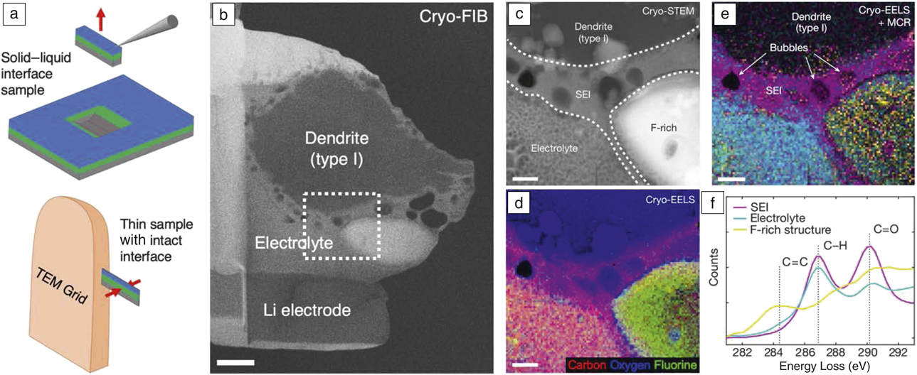
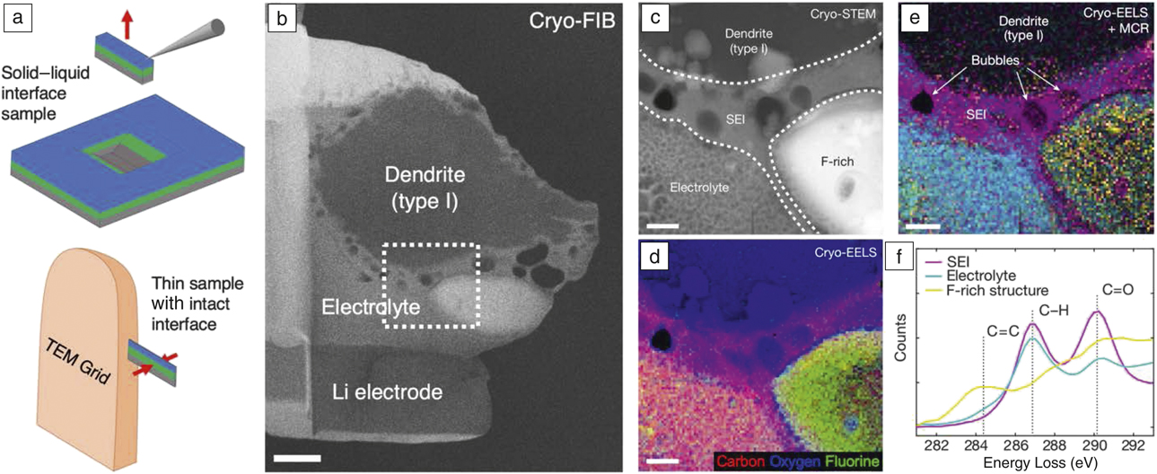
Scanning TEM (STEM) can provide atomic-scale structural, elemental, and chemical analysis, but has traditionally been limited to hard materials at room temperature, such as solid–solid interfaces.Reference Botton38–Reference Mundy, Hikita, Hidaka, Yajima, Higuchi, Hwang, Muller and Kourkoutis40 Recent advancements in paired cryo-FIB liftout sample preparation and analytical cryo-STEM techniques,Reference Zachman, Asenath-Smith, Estroff and Kourkoutis12 however, have begun to allow high-resolution imaging and spectroscopy of intact buried solid–liquid interfaces from within devices. For example, Figure 2a shows a schematic of cryo-FIB liftout preparation and analytical cryo-STEM results for a lithium (Li) dendrite–organic electrolyte interface prepared from a cycled Li-metal coin cell battery (electrolyte composition: 1M LiPF6 in 1:1 ethylene carbonate:dimethyl carbonate).Reference Zachman, Tu, Choudhury, Archer and Kourkoutis13 In this study, rapid cooling preserved the native interface structure and chemistry, avoiding the significant alterations that traditional sample washing and drying can induce. Cryo-FIB liftout techniques were then used to generate electron-transparent cross-sectional lamellae of the intact interface (Figure 2b). This allowed an extended solid-electrolyte interphase (SEI), ∼400-nm thick, to be observed by high-angle annular dark-field (HAADF) cryo-STEM (Figure 2c). Cryo-STEM electron energy-loss spectroscopy (EELS) showed that this extended SEI contained increased oxygen compared to the electrolyte and encircled a F-rich structure also observed by HAADF (Figure 2d). Statistical analysis of the carbon K-edge revealed an increased proportion of C=O bonds in the SEI layer compared to the electrolyte, consistent with ethylene carbonate solvent molecules reacting to form lithium ethylene dicarbonate (Figure 2e, f). A byproduct of this reaction is ethylene gas,Reference Metzger, Strehle, Solchenbach and Gasteiger41 which contains C=C bonds and is thought to bond to LiF,Reference Szczȩśniak and Ratajczak42 possibly explaining the SEI bubbles and the correlated fluorine and C=C bonds observed in the F-rich structure. These correlated chemical and morphological results could not be previously obtained for intact solid–liquid interfaces with this resolution and site-specific detail. Results such as these are anticipated to contribute to our understanding of the primary mechanisms involved in the safety and performance of energy-storage devices such as in Li-metal batteries.
Cryo-focused ion beam (cryo-FIB) liftout preparation and subsequent analytical cryo-scanning transmission electron microscopy (cryo-STEM) characterization of an intact solid–liquid interface from a Li-metal coin cell battery. (a) Schematic depicting cryo-FIB liftout preparation of intact buried solid–liquid interface for analytical cryo-STEM. (Top) An interface is exposed by cryo-FIB milling, and a cross-sectional lamella is extracted on a cold nanomanipulator. (Bottom) The intact interface is then attached to a TEM grid and thinned to electron transparency. (b) Electron transparent lamellae containing intact Li electrode–organic electrolyte–Li dendrite interfaces (electrolyte composition: 1M LiPF6 in 1:1 ethylene carbonate:dimethyl carbonate). Dashed box indicates region where (c–f) were acquired. Scale bar = 1 µm. (c) Annular dark-field cryo-STEM image of the interface between the Li dendrite and electrolyte. (d) Simultaneously acquired cryo-STEM electron energy-loss spectroscopy (EELS) map. (e) Statistical analysis of the carbon K-edge EELS fine structure reveals carbon bonding environment, with colors corresponding to the spectral components in (f). (f) Carbon K-edge spectral components corresponding to the bonding environments mapped in (e). (c–e) Scale bars = 300 nm.Reference Zachman, Tu, Choudhury, Archer and Kourkoutis13 Note: SEI, solid–electrolyte interface; MCR, multivariate curve resolution.
In the future, dose-efficient phase-retrieval imaging techniques such as electron ptychography may allow increased resolution of soft interphase materials to be achieved with a low dose.Reference Jiang, Chen, Han, Deb, Gao, Xie, Purohit, Tate, Park, Gruner, Elser and Muller43,Reference Lozano, Martinez, Jin, Nellist and Bruce44 In addition, direct electron detectors for spectroscopy will increase the signal-to-noise ratio of acquired spectra, reducing the necessary dose and enabling higher spatial-resolution spectroscopic mapping of these materials.Reference Baek, Goodge, Lu, Hikita, Hwang and Kourkoutis45,Reference Hart, Lang, Leff, Longo, Trevor, Twesten and Taheri46
Dynamic imaging of solid–liquid interfaces
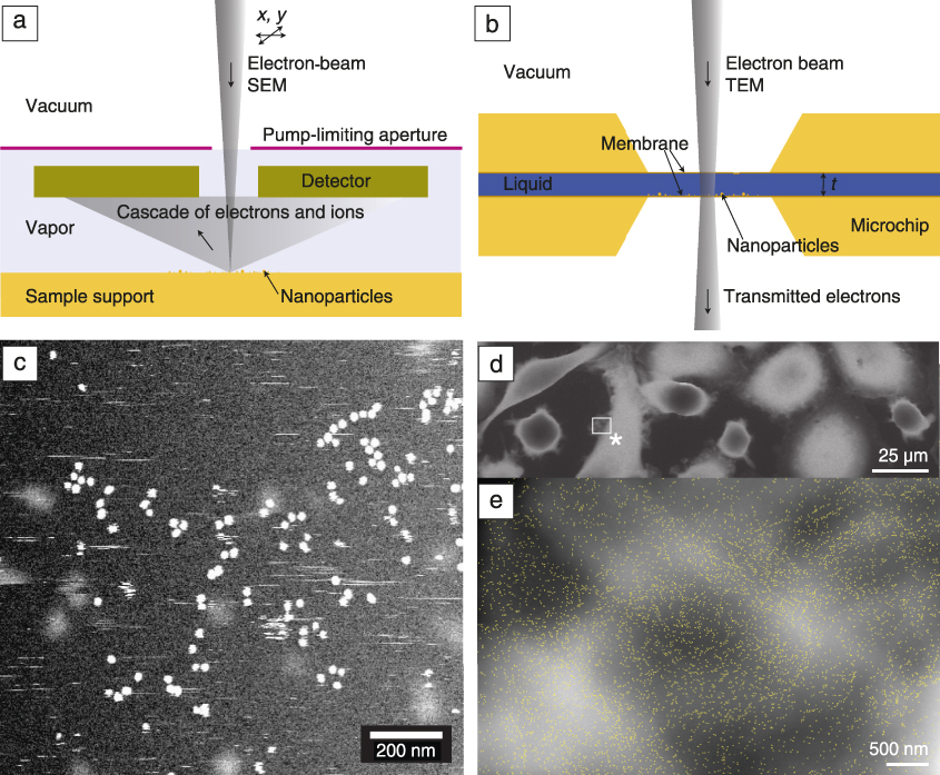
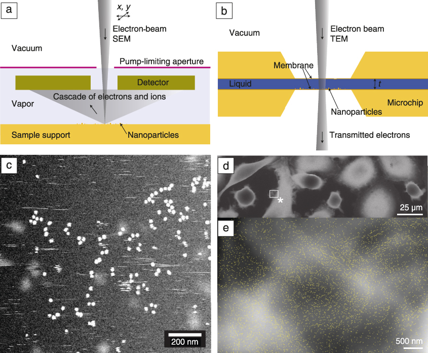
The static characterization techniques discussed up to this point can be paired with LPEM to additionally obtain information about kinetics, dynamics, and reaction mechanisms of specimens directly in a liquid environment.Reference Ross, Wang and de Jonge25,Reference de Jonge and Ross47–Reference Ruska49 Two basic types of experimental LPEM systems exist—open and closed. In open-LPEM systems (Figure 3a), a liquid specimen is placed in the vacuum chamber of the electron microscope, whereby one or more pump-limiting apertures are integrated in the microscope to accomplish a separation of the high vacuum of the microscope column and the low vacuum around the specimen.Reference Ruska49,Reference Danilatos50 Alternatively, ionic liquids that are stable in vacuum can be directly used without the need for a pump-limiting aperture.Reference Wang51 In closed-LPEM systems (Figure 3b), a liquid specimen is separated from the vacuum of the electron microscope by means of a thin, electron-transparent membrane, typically made of silicon nitrideReference Williamson, Tromp, Vereecken, Hull and Ross26,Reference Parsons, Matricardi, Moretz and Turner48,Reference de Jonge, Peckys, Kremers and Piston52 or graphene.Reference Textor and de Jonge53,Reference Yuk, Park, Ercius, Kim, Hellenbusch, Crommie, Lee, Zettl and Alivisatos54
Two basic types of liquid-phase electron microscopy. (a) An open system in which the specimen is maintained in a vapor environment at low pressure separated from the electron optics in high vacuum by means of a pump-limiting aperture. In the case of scanning electron microscopy (SEM), a cascade of electrons and ions is generated upon electron-beam impact, thus enhancing detection. (b) The liquid is fully separated from the vacuum in the electron microscope in a closed system. In TEM, the electron beam passes through two membrane windows. (c) Gold nanoparticles imaged in liquid in a closed system revealing both stationary particles assembled in clusters and chains as well as moving nanoparticles (visible as streaks). (d) Cancer cells imaged in an environmental SEM. (e) Quantum dot nanoparticles (marked as yellow dots) attached to HER2 growth factor receptors in the plasma membrane of cells are used to examine drug effects. The image was acquired at the position of the * in panel (d).Reference de Jonge and Ross47,Reference Verch, Pfaff and de Jonge62,Reference Peckys, Korf, Wiemann and De Jonge65 Note: t, thickness of liquid.
The advantage of LPEM is that it facilitates the study of dynamic processes by providing access to the structure at solid–liquid interfaces without the need to convert the sample to a fully solid, frozen state. Additionally, recent evidence has shown that under certain circumstances, radiation damage can be reduced compared to cryo-EM.Reference Keskin and de Jonge55,Reference Mirsaidov, Zheng, Casana and Matsudaira56 However, a major point of concern is the reactive electrochemical environment created by the electron beam in the liquid.Reference Schneider, Norton, Mendel, Grogan, Ross and Bau57 Experiments have to be carefully designed, executed, and interpreted to separate effects of the beam from the phenomena that one aims to examine.Reference Woehl, Jungjohann, Evans, Arslan, Ristenpart and Browning58 LPEM in a closed system is also typically limited to a maximal sample thickness of several micrometers, which is smaller compared to cryo-FIB/APT/STEM, since the sample must fit between the windows of the cell.
LPEM has been used to study processes such as nanoparticle growthReference Zheng, Smith, Jun, Kisielowski, Dahmen and Alivisatos27,Reference Ahmad, Wang, Nelayah, Ricolleau and Alloyeau59,Reference Evans, Jungjohann, Browning and Arslan60 and movement in liquidReference Kim, Ou, Jones, Song and Chen61,Reference Verch, Pfaff and de Jonge62 (Figure 3c), biomineralization,Reference Smeets, Cho, Kempen, Sommerdijk and De Yoreo63 electrochemistry at nanoscale interfaces,Reference Harrison, Zavadil, Hahn, Meng, Elam, Leenheer, Zhang and Jungjohann19,Reference Leenheer, Jungjohann, Zavadil and Harris21–Reference Mehdi, Qian, Nasybulin, Park, Welch, Faller, Mehta, Henderson, Xu, Wang, Evans, Liu, Zhang, Mueller and Browning23,Reference Williamson, Tromp, Vereecken, Hull and Ross26 drug–receptor interaction mechanisms in cancer cellsReference Peckys, Korf and de Jonge64,Reference Peckys, Korf, Wiemann and De Jonge65 (Figure 3d–e), and more. Cryo-EM and LPEM are expected to be paired in the future to reveal a more complete picture of solid–liquid morphology, chemistry, and processes than could be obtained by either technique individually. Cryo-EM will provide high-resolution morphological and chemical information from interfaces within large samples, while LPEM will provide dynamic structural information,Reference de Jonge, Houben, Dunin-Borkowski and Ross66 each technique contributing a piece to the scientific puzzle.
Outlook
High-resolution structural and chemical analyses of intact solid–liquid interfaces are now possible using cryo-FIB to prepare materials for characterization by cryo-STEM and APT, which can complement the dynamic imaging of LPEM to provide a more complete picture of the interface. Adoption of these new techniques has the potential to greatly enhance our understanding of a wide variety of processes at solid–liquid interfaces, such as chemical absorption, the electrical double layer, corrosion products, particulate transfer through membranes, exfoliation of two-dimensional materials in liquids, and biochemical reactions with material surfaces, including implants. These tools will therefore contribute to a deeper understanding of processes occurring at solid–liquid interfaces across many disciplines in the physical sciences.
Acknowledgments
K.J. acknowledges support from the Center for Integrated Nanotechnologies and M.J.Z.’s contribution was conducted at the Center for Nanophase Materials Sciences, which are US Department of Energy (DOE) Office of Science User Facilities. N.d.J. acknowledges E. Arzt for his support through the INM–Leibniz Institute for New Materials. D.P. acknowledges support for the development of the cryo-APT capability from the DOE-BER Mesoscale to Molecular Bioimaging Project FWP No. 66382, the Chemical Imaging Initiative LDRD Program at Pacific Northwest National Laboratory, and Environmental Molecular Sciences Laboratory (EMSL) capability development funding, and support enabling cryo-FIB and the analysis of corroded glass from the Center for Performance and Design of Nuclear Waste Forms and Containers, an Energy Frontier Research Center funded by the DOE, Office of Science, Basic Energy Sciences under Award No. DE-SC0016584, and support from DOE-BER Mesoscale to Molecular Bioimaging Project FWP No. 66382 and EMSL capability development funding. Sandia National Laboratories is a multimission laboratory managed and operated by National Technology and Engineering Solutions of Sandia, LLC, a wholly owned subsidiary of Honeywell International, Inc., for the DOE’s National Nuclear Security Administration under Contract No. DE-NA-0003525. The views expressed in the article do not necessarily represent the views of the DOE or the United States Government.

Michael J. Zachman is a staff scientist in the Center for Nanophase Materials Sciences at Oak Ridge National Laboratory. He received his PhD degree in applied physics from Cornell University in 2018. His research includes the development of cryogenic focused ion beam and analytical cryogenic scanning transmission electron microscopy (STEM) techniques for studying intact solid–liquid interfaces at high resolution, and recently has focused on advancing and utilizing multidimensional STEM and monochromated electron energy-loss spectroscopy techniques for understanding processes in quantum and energy materials. Zachman can be reached by email at zachmanmj@ornl.gov.

Niels de Jonge has been a senior group leader at the INM–Leibniz Institute for New Materials, Germany, since 2012, and an honorary professor of physics at Saarland University, Germany. He received his master’s degree in physics from the University of Amsterdam, The Netherlands, in 1994, and his PhD degree in biophysics from the University of Freiburg, Germany, in 1999. He subsequently worked as senior scientist at Philips Research, The Netherlands, from 2000 to 2005. He studied liquid-phase electron microscopy at Oak Ridge National Laboratory from 2005 to 2010, while also serving as an assistant professor at Vanderbilt University School of Medicine from 2007 to 2011. De Jonge can be reached by email at Niels.deJonge@leibniz-inm.de.

Robert Fischer is the manager of the Focused Ion Beam Laboratory at the University of Oregon. He received his MS degree in applied physics from the University of Oregon. His research focuses on many sample types ranging from extraterrestrial geological samples to next-generation integrated circuits, and he has learned several application-specific techniques that have allowed him to assist researchers with many different challenges. Fischer can be reached by email at robertf@uoregon.edu.

Katherine Jungjohann is a staff scientist at the Center for Integrated Nanotechnologies (CINT) at Sandia National Laboratories. She is the thrust leader for the In Situ Characterization and Nanomechanics Thrust at CINT, and the co-leader of the Microscopy Society of America’s Focused Interest Group on Electron Microscopy in Liquids and Gases. Her research includes the development of new capabilities for in situ transmission electron microscopy imaging of environmentally relevant materials processes. Her current research focuses on energy-storage interfaces and corrosion mechanisms. Jungjohann can be reached by email at kljungj@sandia.gov.
Daniel E. Perea is a senior staff scientist in the Environmental Molecular Sciences Laboratory at Pacific Northwest National Laboratory. He received his PhD degree in materials science and engineering from Northwestern University in 2009. His current research includes the development of unique cryogenic-based techniques and protocols to pioneer the use of atom probe tomography to probe the composition and structure of hydrated materials. His research also explores inorganic biominerals, geological minerals, catalysts, and complex oxides. Perea can be reached by email at daniel.perea@pnnl.gov.