1. Introduction
Pipelines are critical infrastructure for material transport and are widely used in petroleum, chemical, nuclear, urban, and agricultural systems. They perform essential functions such as drainage, heating supply, power delivery, gas distribution, and bulk material transport, forming an indispensable network within modern cities and industrial systems. As most pipelines are buried underground, maintenance operations often face confined spaces, complex geometries, and potentially hazardous environments. Conventional manual inspection and maintenance methods are therefore inefficient and risky. In this context, pipeline robots have emerged as an effective solution to enhance operational intelligence, safety, and coverage [Reference Yuan1]. Since their inception, pipeline robots have evolved from structurally simple platforms with limited functionality into systems integrating multiple sensors for improved environmental perception and motion adaptability. In recent years, advances in navigation algorithms, communication systems, and multimodal data fusion have further driven the development of pipeline robots toward higher levels of autonomy and the capability to perform complex tasks [Reference Kahnamouei and Moallem2]. This paper systematically reviews the technological evolution of pipeline robots and summarizes representative platforms across different stages, as illustrated in Figure 1.
A timeline of the development history of representative technologies of pipeline robots.

Figure 1. Long description
Panel A: In 2003, the Multi-legged pipe robot MORITZ from the Technical University of Munich, Germany, was developed. In 2005, the Inchworm-type pipeline robot from Shanghai Jiao Tong University, China, was introduced. In 2007, the Foot-driven robot KANTARO from FAIS-Robotics Office, Japan, was created. In 2009, the Wall-pressing track-driven robot PAROYS from Yonsei University, South Korea, was developed. In 2012, the Screw-driven robot from Ritsumeikan University, Japan, was introduced. In 2014, the Wall-pressing wheel-driven pipeline robot from Sungkyunkwan University, South Korea, was created. In 2016, the Spherical frame flying pipeline robot from Cranfield University, UK, was developed. In 2018, the Compound-driven robot of Sharjah University in Arabia was introduced. In 2021, the Quadruped pipeline robot from South China University of Technology, China, was created. In 2023, the V-shaped wheel-driven robot from Ritsumeikan University, Japan, was developed. In 2025, the Space Station Pipeline Robot from Beijing Institute of Technology, China, is planned. Panel B: In 1997, the Track-driven pipeline robot from Shanghai Jiao Tong University, China, was developed. In 1986, the L-shaped wheel-driven robot from Tokyo Institute of Technology, Japan, was introduced. In 1978, the Wheel-legged robot IPRIV from France was created. In the 1950s, the Medium pressure differential robot PIG from Weatherford Company, USA, was developed.
The technological evolution of pipeline robots began in the mid-20th century, when Weatherford pioneered the development of the Pipeline Inspection Gauge (PIG) [Reference Bredin3]. Driven passively by a fluid-pressure differential acting across polyurethane sealing cups, this system laid the foundation for the development of autonomous in-pipe robotic platforms. By the 1970s, growing demands in the petroleum, natural gas, and nuclear industries stimulated research into active locomotion mechanisms. Vertut [Reference Vertut and Liégeois4] proposed the IPRIV wheeled-leg pipeline robot, which, for the first time, established the dual-functional paradigm of support-adhesion and driving-mobility, laying a theoretical foundation for future design innovations. The 1980s witnessed significant structural diversification, driven by advancements in control theory and sensor technology. Representative achievements during this period include the MOUSE wheeled robot developed in the United States, the MOGRER system from Japan, and the L-shaped wheeled robot proposed by Toshio Fukuda. During this stage, the fundamental configurations of wheeled, tracked-type, and peristaltic locomotion systems were gradually established. In the 1990s, Hirose et al. [Reference Hirose, Ohno, Mitsue and Suyama5] further advanced research on flexible structures with the Thes series of robots. In 1997, Lu et al. [Reference Lu, Song and Shen6] introduced an adaptive tracked-type pipeline robot. Entering the 21st century, the field has shifted toward intelligent and multifunctional integration. In 2003, Zagler [Reference Zagler and Pfeiffer7] designed MORITZ, an eight-legged crawling robot capable of complex and agile locomotion. In 2005, Yu et al. [Reference Yu, Ma and Cao8] developed a peristaltic robot inspired by the motion of earthworms. Actuated by shape memory alloys (SMAs), the robot achieved movement through axial contraction and extension, enabling navigation in 2-inch diameter pipes. In 2007, Amir et al. [Reference Nassiraei, Kawamura, Ahrary, Mikuriya and Ishii9] introduced MAKRO, a 21-DOF snake-like robot with exceptional 3D maneuverability. Since then, significant advancements in drive and mobility systems have continued to emerge. In 2011, Park et al. [Reference Park, Hyun, Cho, Kim and Yang10] developed PAROYS-II, a tri-tracked-type robot capable of traversing bends and conical segments with structural uniformity. In 2011, Nishimura. et al. [Reference Nishimura, Kakogawa and Ma11] introduced a dual-motor helical drive robot designed to navigate straight sections, curves, and T-junctions. In 2014, Yang et al. [Reference Yang, Kim, Suh, Choi, Mun, Park, Moon and Choi12] introduced a 3D differential-wheeled robot incorporating wall-press force adjustment. In 2016, Malandrakis et al. [Reference Malandrakis, Dixon, Savvaris and Tsourdos13] designed a spherical aerial robot intended for operations in tunnels and cavernous environments. In 2018, Waleed et al. [Reference Waleed, Mustafa, Mukhopadhyay, Abdel-Hafez, Jaradat, Dias, Arif and Ahmed14] proposed a compound drive robot. In 2023, Zhang et al. [Reference Zhang, Yuan, Hong and Cai15] developed a quadrupedal wall-climbing robot designed for stable locomotion within pipe interiors. Kakogawa et al. [Reference Kakogawa, Murata and Ma16] introduced a hinged V-type wheeled robot capable of adapting to T-junction geometries. In 2025, Zheng et al. [Reference Zheng, Wang, Li, Zhao, Jiang, Huang and Ceccarelli17] proposed a self-adaptive pipeline robot; it was deployed and tested aboard the China Space Station, representing a milestone in extending robotic pipe inspection to microgravity environments. In summary, pipeline robotics has progressed from basic passive mechanisms to highly integrated platforms incorporating active locomotion, structural adaptability, and intelligent control. Current research trends are shifting from single-mode locomotion (wheel-driven, foot-driven, or tracked-type) to multimodal hybrid systems and from linear pipe traversal to adaptability within complex, branched network environments. This review focuses on drive architectures and coordinated control to provide a systematic analysis of key technologies, representative implementations, prevailing technical challenges, and prospective development pathways.
Classification diagram of pipeline robot drive types and execution configurations.

2. Research status of pipeline robot drive technology
To meet the diverse operational demands of various pipeline environments, a wide range of locomotion strategies has been developed for pipeline robots. Although no universally accepted classification system currently exists, a commonly adopted taxonomy is illustrated in Figure 2. This paper classifies pipeline robots into three categories according to their actuation mechanisms: passive-driven, self-driven, and hybrid-driven systems [Reference Kazeminasab, Jafari and Banks18].
Passive-driven robots rely on pressure differentials generated by the flow of internal media within the pipeline. These robots typically incorporate sealing elements, such as polyurethane cups, to conform to the inner pipe wall, enabling forward propulsion without internal actuation. As such, they lack self-contained power or mobility systems. In contrast, self-driven robots are self-powered and equipped with internal actuators, enabling autonomous navigation and adaptation to dynamic or unstructured environments. Compound-driven systems combine passive and active components, achieving a balance between energy efficiency and locomotion versatility. Self-driven pipeline robots can be further classified by propulsion mechanism, including wheel-driven, tracked-type, foot-driven, inchworm-type, biomimetic snake-type, flying-type, and screw-driven. Several of these architectures can be further categorized into wall-pressing and non-wall-pressing types. Wall-pressing robots employ radially arranged drive modules that maintain circumferential contact with the pipe wall and incorporate active mechanisms to adjust the wall force, enabling stable locomotion in both vertical and curved sections. In contrast, non-wall-pressing robots interact only with the pipe floor and are better suited for horizontal or low-inclination pipelines under minimal load conditions.
2.1. Passive-driven pipeline robot
Passive-driven pipeline robots rely entirely on the pressure differential generated by internal fluid flow for propulsion and are not equipped with onboard actuators for thrust generation. Structurally, they typically employ sealing cups or elastic sealing rings that maintain tight contact with the pipe wall. This configuration establishes a stable pressure difference between the front and rear of the robot, enabling unidirectional axial motion under fluid driving, as illustrated in Figure 2(a). Because propulsion does not depend on active drive units, passive systems feature compact structures, high reliability, and stable long-distance operation. They have been widely applied in pigging and in-line inspection of oil and gas pipelines, particularly in long, straight segments and large-scale inspection scenarios. The most representative passive-driven platform is the PIG. In the 1950s, Weatherford first developed the Pipeline Inspection Gauge, as shown in Figure 3(a). Initially designed for debris removal, it later evolved into an inspection platform integrating multiple sensors. In 2007, ROSEN Group introduced a speed-controllable passive inspection system for gas pipelines [Reference Aue, Brown, Humphreys and Sutherland19, Reference Beuker, Brockhaus and Lindner20], as shown in Figure 3(b). The system acquires velocity and pressure differential data via onboard sensing and electronics and indirectly regulates traveling speed by adjusting the opening of a front throttling valve to modulate the internal flow characteristics.
Different types of PIG pipeline robots (a) Weatherford Company’s PIG robot, (b) ROSEN Company’s PIG robot.

2.2. Self-driven pipeline robot
2.2.1. Wheel-driven pipeline robot
Wheeled in-pipe robots utilize rolling wheels as their primary locomotion mechanism and can be broadly classified into non-wall-pressing and wall-pressing types. Non-wall-pressing designs adopt a ground-vehicle-like configuration, making them suitable for horizontal movement but limited in ascending steep or vertical pipe sections. In contrast, wall-pressing wheel-driven robots feature multiple wheels arranged circumferentially along the inner wall of the pipe. These wheels apply adjustable normal forces – either passively or actively – ensuring sufficient traction and stable climbing performance in vertical or inclined pipelines.
Non-wall-pressing wheel-driven pipeline robot. These robots adopt a locomotion principle inspired by ground vehicles. As shown in Figure 2(b), it typically utilizes hub motors to directly actuate the wheels, generating traction through frictional contact with the bottom surface of the pipe. This configuration offers a compact structure, low energy consumption, and a simplified control system. Such designs are well-suited for pipelines with smooth inner surfaces, uniform diameters, and gentle slopes, providing high versatility and ease of maintenance. However, their adaptability is limited in complex or uneven pipeline environments.
In 2022, Thung et al. [Reference Thung-Od, Kanjanawanishkul, Maneewarn, Sethaput and Boonyaprapasorn21] developed a magnetic omnidirectional wheel-driven pipeline robot, as shown in Figure 4(a). By integrating omnidirectional wheels with a permanent magnet adhesion mechanism, the robot achieves high stability during both horizontal and vertical motion within ferromagnetic pipelines. Another wireless pipeline robot developed by Wuhan Zhongyi Co. (Figure 4(b)) [Reference Co22] features independently driven wheels powered by onboard motors, enabling differential steering and in-place 360
 $^\circ$
rotation. Its battery system is a fully battery-operated propulsion system that ensures high mobility in constrained environments. In contrast, a tethered pipeline robot designed by Schroeder Co. (Figure 4(c)) [23] utilizes dual DC motors and a tether for power supply and data communication. Equipped with a displacement-based steering mechanism, the system is well-suited for navigating low-gradient pipelines with complex geometries.
Typical non-wall-pressing wheel-driven pipeline robot (a) Magnetic universal wheel-driven pipeline robot, (b) Wireless wheel-driven pipeline robot, (c) Wired wheel-driven pipeline robot.

Wall-pressing wheel-driven pipeline robot. Wall-pressing wheel-driven pipeline robots employ active or passive wall-pressing mechanisms to distribute multiple wheel modules circumferentially around the robot body, ensuring consistent contact with the inner pipe wall, as shown in Figure 2(c). This configuration provides enhanced traction and stability, enabling reliable traversal through complex environments, including variable-diameter segments, vertical climbs, and obstacle-laden sections. Common configurations include two, three, four, or six wheel arms symmetrically arranged around the central axis to optimize stability and adaptability [Reference Verma, Kaiwart, Dubey, Naseer and Pradhan24].
Since 1999, Sungkyunkwan University has led the development of the MRINSPECT series of wall-pressing wheel-driven pipeline robots, with iterative enhancements in adaptability and mobility, as shown in Figure 5 [Reference Choi, Ryew and Cho25–Reference Yuwen32]. The early MRINSPECT-I used a passive spring-based expansion mechanism, limiting its maneuverability and adaptability. MRINSPECT-III, which incorporated a motorized universal joint for actively controlled steering. Later models, MRINSPECT-IV and -V, adopted fully independent wheel-driven systems and modular torque distribution mechanisms, significantly improving performance in curved and vertical pipelines. In 2013, MRINSPECT-VI and VI + implemented triaxial differential drives, followed by MRINSPECT-VII with a four-axis differential coupling system that enhanced force allocation and traction control via dynamic multi-axis coordination.
Parallel advancements have also been made globally. In 2017, Xu et al. [Reference Xu, Lu, Yang, Feng and Shen33] designed a wheel-based grinding robot for internal pipe wall processing (Figure 6(a)), featuring front-wheel servo actuation, passive rear wheels, and a clamping structure for enhanced stability and maneuverability. In 2023, Kakogawa et al. [Reference Kakogawa, Murata and Ma16] introduced a V-shaped hinged wheeled robot (Figure 6(b)), incorporating two torsional passive joints and one active joint actuated by a polyurethane-based Series Elastic Actuator (SEA). By switching from torque to position control, the robot demonstrated robust traversal through vertical T-junctions. In the same year, Liu et al. [Reference Liu, Luo, Lu and Wu34] developed a variable-diameter wheel-driven robot (Figure 6(c)) powered by six miniature planetary-geared DC motors, utilizing gear transmission and frictional traction for locomotion. In 2024, Liu et al. [Reference Liu, Sun, Cao, Wu, Xu, Han, Wen, Shen, Chen, Xu, Yu and Ji35] introduced a biomimetic wheel-driven robot (Figure 6(d)), inspired by the claw-hooked legs of Trypoxylus dichotomus and the dry adhesion of geckos. The robot combines a wheel-leg hybrid structure with an active steering actuator, enabling stable adhesion and locomotion on both horizontal and vertical surfaces. Concurrently, Cox et al. [Reference Adam, Colaw, Richer, Galla and Hurmuzlu36] proposed MoRIS, a modular inspection robot based on a spinal structure concept (Figure 6(e)). Its 120
 $^\circ$
circumferentially distributed passive suspension wheels provide self-balancing contact forces, allowing effective navigation in sharply curved pipeline environments.
MRINSPECT series pipeline robot.

Typical wall-pressing wheel-driven pipeline robot (a) Grinding wheel robot, (b) articulated V-shaped wheel robot, (c) wheel variable diameter pipe robot, (d) bionic wheel pipe robot, (e) MoRIS pipe robot.

Figure 6. Long description
The image contains five separate photos of different wall-pressing wheel-driven pipeline robots. Panel A shows a grinding wheel robot, which appears to be designed for pipe maintenance or inspection. Panel B depicts an articulated V-shaped wheel robot, featuring a flexible design likely for navigating bends and complex pipe structures. Panel C illustrates a wheel variable diameter pipe robot, which can adjust its wheel diameter to fit different pipe sizes. Panel D presents a bionic wheel pipe robot, mimicking biological forms for enhanced mobility and adaptability. Panel E displays the MoRIS pipe robot, designed for versatile and stable locomotion within pipe interiors. Each robot showcases unique design features and technological advancements in pipeline inspection and maintenance.
2.2.2. Tracked-type pipeline robot
Tracked-type pipeline robots share a similar overall architecture with wheel-driven systems but utilize continuous tracks, providing a larger contact surface area and more uniform load distribution. This configuration significantly enhances traction and motion stability, making them particularly suitable for high-gradient, low-friction, or uneven pipeline surfaces. Compared to wheeled counterparts, tracked-type robots offer superior environmental adaptability and traversal capabilities under harsh conditions, with stronger traction and improved anti-slip performance.
Non-wall-pressing tracked-type pipeline robot. These robots employ a bottom-adhering track configuration, relying on frictional interaction between the tracks and the inner pipe floor for propulsion, as shown in Figure 2(d). Structurally simple and compact, they are well-suited for pipelines with uniform diameters, low inclination, and straight-line paths. However, their adaptability in complex environments is limited. In cases involving bends, inclines, or irregular geometries, their obstacle-surmounting capability is significantly constrained.
In 2018, Ciszewski et al. [Reference Ciszewski, Buratowski and Giergiel37] developed a tracked-type pipeline robot featuring a dual-track modular design, as shown in Figure 7(a). Each track is independently driven by three motors, offering enhanced mobility. However, the limited number of track modules restricts adaptability in complex pipeline environments. The AURORA robot, developed in the United States, adopts a single-track and wheel hybrid architecture [38], as shown in Figure 7(b). Compact and maneuverable, it is battery-powered and capable of bidirectional movement, offering steering functionality in both forward and reverse modes.
Typical non-wall-pressing tracked-type pipeline robot (a) Double-track variable diameter pipe robot, (b) Single-track pipe robot AURORA.

Wall-pressing tracked-type pipeline robot. By integrating tracked-type locomotion with wall-pressing mechanisms, these robots enhance radial contact force, thereby improving traction and locomotion stability, as shown in Figure 2(e). Compared to non-wall-pressing designs, this configuration is better suited for complex pipelines with moisture, sediment buildup, or steep inclines. It offers superior obstacle-climbing performance and adaptability under demanding operational conditions.
In 2011, Park et al. [Reference Park, Hyun, Cho, Kim and Yang10] developed the PAROYS-II modular tracked-type platform, as shown in Figure 8(a), featuring three motorized diameter-adjustment modules spaced 120
 $^\circ$
apart. This setup enables active control of track inclination and precise adaptation to pipelines ranging from
 $\Phi 400 \mathrm{\,mm}$
to
 $\Phi 700 \mathrm{\,mm}$
. In 2012, Kwon et al. [Reference Kwon39] proposed a dual-module robotic system, Figure 8(b), incorporating three motor-driven continuous wall-contact (CWC) tracked-type chains along with an embedded four-bar linkage and compression springs for passive radial expansion. This design enhances the contact area in small-diameter pipelines
 $(\Phi 80-\Phi 100 \mathrm{\,mm})$
, but its passive mechanism limits vertical climbing capabilities [Reference Yang40]. In 2014, Kakogawa et al. [Reference Kakogawa, Ma and Hirose41] introduced an underactuated parallel-tracked-type pipeline robot, as shown in Figure 8(c), utilizing a bevel gear-based differential drive to enable dual-mode locomotion (crawling/climbing) with a single actuator. Its parallelogram-inspired topology ensures constant track length while supporting adaptive diameter adjustment, obstacle negotiation, and impact absorption. In 2020, Zhao et al. [Reference Zhao, Zhang and Kim42] proposed a tri-tracked-type cooperative robotic system, as shown in Figure 8(d), composed of three independently driven track modules. Each module features a motorized linear actuator, enabling individual speed and radial force adjustment, which enhances adaptability to variable pipeline geometries. In 2024, Wang et al. [Reference Wang, Wang, Peng, Zhang, Gao, Wang, Gao, Luo and Chen43] designed and developed a new type of deformable pipeline inspection robot. By adopting multiple motion modules arranged at a 60-degree angle along the central axis and utilizing pneumatic drive, the robot achieved active and passive deformation capabilities, with a deformation rate as high as 191.4%, enabling it to adaptively adjust its shape in complex pipeline environments.
Typical wall-pressing tracked-type pipeline robot.

2.2.3. Foot-driven pipeline robot
Employing foot-driven architectures in combination with coordinated gait control to achieve stable locomotion through periodic alternating support, as shown in Figure 2(f). This design offers enhanced adaptability to complex environments and improved obstacle-climbing capabilities. The legged configuration is particularly suitable for navigating challenging pipeline scenarios, including branch junctions, multiple bends, and irregular diameter transitions.
Non-wall-pressing foot-driven pipeline robot. In 2023, Zhang et al. [Reference Zhang, Yuan, Hong and Cai15] developed a quadrupedal wall-climbing robot designed for stable locomotion within pipe interiors, as shown in Figure 9(a). Utilizing a statically stable gait strategy along with a lightweight structure and highly controllable leg-end actuators, the robot demonstrates excellent surface adhesion and stable locomotion. Each leg joint is actuated by bus-controlled servos, and each foot is equipped with a universal suction cup. A compact onboard vacuum pump generates negative pressure, enabling secure adhesion to curved surfaces. In 2022, Jang et al. [Reference Youhyun, Woojin, Lee, Kim and Kim44] introduced a quadrupedal robotic system, shown in Figure 9(b). equipped with a hierarchical gait controller that enables seamless transitions between locomotion modes, ensuring stable navigation within confined pipeline environments. The system utilizes model predictive control to compute joint impedance and torque in real time, allowing the robot to effectively overcome challenges such as slippery surfaces and localized obstacles. In 2025, Tmsuk introduced the foot-driven pipeline robot SPD-X [45], as shown in Figure 9(c). The robot features 16 independently controlled legs, each actuated by multiple motors for precise joint manipulation. By coordinating the motion of all limbs through a multi-limb control strategy, the SPD-X achieves stable locomotion and effective obstacle negotiation in complex pipeline environments, reaching a top speed of 0.3 km/h.
Typical non-wall-pressing foot-type pipeline robot.

Figure 9. Long description
The image contains three separate photos of pipeline robots. Panel A shows a typical non-wall-pressing foot-type pipeline robot. The robot has multiple legs arranged radially around a central body, each leg ending in a foot. The central body contains various electronic components and wiring. Panel B depicts a wheeled-leg pipeline robot. This robot has a combination of wheels and legs, designed to provide both support-adhesion and driving-mobility. The legs are positioned to assist in navigation through pipes. Panel C illustrates a tracked-type pipeline robot. This robot features continuous tracks that wrap around the body, providing stability and mobility within pipe environments. The tracks are designed to adapt to different pipe geometries and ensure smooth movement.
Wall-pressing foot-driven pipeline robot. In 2015, the Technical University of Munich developed a bio-inspired foot-driven pipeline robot named MORITZ [Reference Tomita, Tanaka and Nakamura46, Reference Yamazaki, Tanise, Kamata, Taniguchi and Nakamura47], as shown in Figure 10. Inspired by the locomotion patterns of foot-driven insects, MORITZ demonstrates high maneuverability and adaptability to complex pipeline geometries. The robot adopts an eight-legged crawling configuration, with each leg actuated independently by a compact DC motor. Through biomimetic gait planning, it achieves both forward and reverse locomotion, enabling traversal of bends, T-junctions, inclined sections, and vertical shafts. Despite its advanced adaptability, MORITZ presents several limitations. Its structurally complex design and highly integrated control architecture lead to reduced drive efficiency and slower response time. In addition, its physical form factor restricts compatibility with small-diameter pipelines, thereby limiting its applicability in certain operational scenarios.
Bionic wall-pressing foot-driven pipeline robot MORITZ.

2.2.4. Inchworm-type pipeline robot
Inchworm-type pipeline robots emulate biological peristalsis by sequentially actuating modular segments to generate traveling contraction waves that propel the robot forward. These systems utilize flexible materials or deformable structures, allowing highly adaptable locomotion in confined and tortuous pipeline environments. The core operating principle involves periodic actuation of independently controlled segments to produce directional inchworm-type motion. This class of robots exhibits exceptional obstacle-climbing capabilities and is well-suited for navigating complex, small-diameter, and sharply curved pipelines, particularly those composed of flexible materials. Due to their compact and compliant architecture, inchworm-type robots are especially advantageous in applications requiring inspection or intervention within micro-scale or medical-grade conduits.
Non-wall-pressing inchworm-type pipeline robot. Non-wall-pressing inchworm-type pipeline robots typically rely on intrinsic structural deformation to generate locomotion, as shown in Figure 2(g). Forward movement is achieved through coordinated shape changes across the body segments, forming a traveling wave without active modulation of wall contact force. Wall adherence arises passively from the robot’s structural configuration, offering mechanical simplicity and low power consumption. These features make them suitable for pipelines with uniform diameters and stable friction conditions. However, in complex scenarios such as curved or vertical pipelines, the passive wall contact may result in insufficient traction, thus limiting propulsion effectiveness and operational applicability.
In 2017, Ye et al. [Reference Yanmao, Yaolei, Hu, Guochen, Mingying and Naiming48] proposed a bioinspired inchworm-like robot employing an adhesion-based locomotion strategy, as shown in Figure 11(a). The robot is actuated by six servo-driven rotary joints, which coordinate with suction-based adhesion and release mechanisms to produce inchworm-like motion. This design facilitates repeated attachment and detachment from the pipe wall during each locomotion cycle. In 2025, Jonathan et al. [Reference Tirado, Parvaresh, Seyidoğlu, Bedford, Jørgensen and Rafsanjani49] developed a soft-bodied robot featuring a kirigami-inspired skin, as shown in Figure 11(b). The robot’s structure comprises a pair of antagonistically arranged, fiber-reinforced inflatable actuators with dual internal chambers. A central pattern generator (CPG) produces cyclic signals that control inflation and deflation with a predefined phase offset, resulting in continuous wave propagation along the body. The outer kirigami skin provides anisotropic friction, which, in combination with body deformation, generates directional thrust for forward locomotion.
Typical non-wall-pressing inchworm-type pipe robot (a) Bionic adhesive inchworm pipe robot, (b) soft pipe robot.

Figure 11. Long description
Panel A: A photograph of a non-wall-pressing inchworm-type pipe robot. The robot features multiple segments connected by joints, allowing for flexible movement. It has a sensorized head and an artificial tail, with rigid connectors and foldable kirigami skin visible. Panel B: A detailed diagram of a bionic adhesive inchworm pipe robot. The diagram includes an antagonistic fiber-reinforced inflatable actuator, a rigid connector, and foldable kirigami skin. The kirigami skin is shown in both folded and partially unfolded states. The cross-section of the actuator is also depicted, with labels indicating folds and cuts. Additionally, the diagram shows the segment connector and the overall structure of the robot, including the sensorized head and artificial tail.
Wall-pressing inchworm-type pipeline robot. Wall-pressing inchworm-type robots achieve integrated attachment and propulsion by actively pressing against the inner wall via periodic modulation of body cross-section, as shown in Figure 2(h). Inspired by biological peristalsis, these robots coordinate segmental elongation and contraction to create traveling waves of propulsion, while simultaneously generating controlled radial pressure to maintain stable wall contact. This mechanism greatly enhances performance in vertical or complex pipeline geometries. Owing to their flexible structures and strong environmental adaptability, they are well-suited for pipelines with large diameter variations or steep gradients. However, their operation requires complex actuation schemes, placing stringent demands on control algorithms and material performance.
In 2005, Yu et al. [Reference Yu, Ma and Cao8] developed an SMA-driven inchworm-type pipeline robot, as shown in Figure 12(a), which relied on thermally actuated shape memory alloys combined with mechanical springs to produce alternating contractions. However, uneven thermal deformation introduced stability issues during locomotion. In 2013, Jeon W. et al. [Reference Jeon, Kim, Park and Yang50] proposed a worm-inspired robot, as shown in Figure 12(b), featuring flexible extension and clamping mechanisms that enabled both inchworm-type locomotion and directional steering. In 2021, Ito et al. [Reference Ito, Takaya, Kamata, Okui, Yamada and Nakamura51] designed a soft-bodied pipeline robot capable of simultaneously generating active propulsion and traction, optimized for small-diameter pipe environments, as shown in Figure 12(c). In 2022, Tang et al. [Reference Tang, Du, Jiang, Shao, Dong, Liu and Zhao52] introduced a sub-centimeter inchworm-type robot actuated by dielectric elastomers (DEAs) and integrated with smart composite microstructures (SCMs) for effective anchoring, as shown in Figure 12(d). Voltage-controlled phase shifts allowed modular actuation and precise crawling. In 2023, Lin et al. [Reference Lin, Xu and Juang53] developed a single-actuator soft robot, as shown in Figure 12(e), which exploited highly nonlinear elastic band buckling to generate strong anisotropic friction forces. Coupled with McKibben artificial muscles, the robot demonstrated effective locomotion in horizontal, vertical, curved, and water-filled pipelines. In 2023, Dai et al. [Reference Dai, Liu, Wang, Song, Li and Zhao54] presented a tension-structure-based inchworm-type robot, as shown in Figure 12(f), combining discrete rigid struts with continuous flexible tendons, enabling high shape adaptability. In 2025, Liu et al. [Reference Liu, Ma, Zhang, Shan, Kang, Zheng and Liu55] introduced a cable-free soft crawling robot based on a Kresling origami structure, as shown in Figure 12(g), which utilizes negative pressure-induced axial contraction and torsion to achieve inchworm-like motion via coordinated three-phase actuation.
Typical wall-pressing inchworm-type pipe robot.

2.2.5. Snake-type pipe robot
Snake-like pipeline robots emulate the locomotion of snake-type organisms and are composed of multiple serially connected modules, each capable of multi-degree-of-freedom bending and rotation, as shown in Figure 2(i). By generating coordinated traveling waves across articulated joints, these robots can replicate various snake-inspired gaits, including lateral undulation, screw-driven propulsion, and rectilinear crawling. This bioinspired actuation strategy enables agile and efficient navigation through highly complex pipeline networks.
Non-wall-pressing snake-type pipe robot. In 2004–2008, Johann et al. developed a non-wall-pressing snake-type robot, as shown in Figure 13(a) [Reference Granosik and Borenstein56–Reference Borenstein and Borrell59]. The robot consists of four serially connected joint modules, each integrated with its own drive mechanism. Locomotion is achieved via compliant actuation using tracks and pneumatic bellows, enabling strong path-following capability and obstacle negotiation. However, its relatively high energy consumption and limited vertical adaptability constrain its application to horizontal pipelines. In 2020, Virgala et al. [Reference Virgala, Kelemen, Božek, Bobovský, Hagara, Prada, Oščádal and Varga60] introduced a snake-like robot for narrow pipeline navigation, as shown in Figure 13(b). The robot demonstrated stable locomotion under both dry-slippery and viscous surface conditions. Building upon this, in 2021, the same group proposed a trapezoidal wave-based propulsion mechanism, as shown in Figure 13(c) [Reference Virgala, Kelemen, Prada, Sukop, Kot, Bobovský, Varga and Ferenčík61]. By periodically modulating joint angles to generate traveling trapezoidal waves, the robot achieves continuous forward motion via controlled multipoint frictional contact with the pipe wall.
Typical non-wall-pressing snake-type pipe robot.

Wall-pressing snake-type pipe robot. Wall-pressing snake-like pipeline robots can be broadly categorized into external and internal wall-pressing configurations. In 2022, Takemori et al. [Reference Takemori, Tanaka and Matsuno62] developed an external wall-pressing snake robot, as shown in Figure 14, capable of wrapping around the outer surface of pipelines or cylindrical structures. Mimicking screw-driven coiling and rolling motions of biological snakes, the robot achieves stable locomotion along pipeline exteriors. In 2024, Liu et al. [Reference Jingwei, Man, Yahui, Da and Rui63] introduced a modular, multimodal internal wall-pressing snake robot, as shown in Figure 15. The robot features orthogonally arranged joint modules, each independently actuated by high-torque servomotors for pitch and yaw control. Its locomotion is based on the backbone curve method, wherein joint angles are derived by integrating spatial curvature and torsion functions, enabling the robot to conform precisely to complex 3D pipeline trajectories. Propulsion is achieved via frictional interaction between the robot’s silicone shell and the pipe wall, ensuring stable adhesion and motion in curved or variable-diameter environments.
Typical external pressure wall snake-type pipe robot.

Figure 14. Long description
The image consists of three elements: one photo, one diagram, and one illustration. The photo shows a snake robot climbing a tree. The illustration shows a snake robot climbing a pole. The diagram shows a snake robot with labeled components and a control setup. The purpose of combining these images is to demonstrate the functionality and control mechanism of the snake robot. The main subject is the snake robot, highlighting its ability to navigate different environments and its internal structure. The photo of the snake robot climbing the tree is on the right side. The illustration of the snake robot climbing the pole is in the middle. The diagram on the left shows the snake robot with labels for tight and loose segments, indicating low and high levels of locality. Below the diagram, there is a control setup with a PC, gamepad, power supply, and labeled components of the snake robot, including a rotary connector and sponge rubber.
Typical internal pressure wall snake-type pipe robot.

2.2.6. Flying pipeline robot
Flying pipeline robots achieve contactless, three-dimensional locomotion within confined conduits by leveraging rotor-driven thrust or aerodynamic suspension, as shown in Figure 2(j). This approach fundamentally overcomes the mechanical constraints and frictional resistance associated with traditional wheel-driven or tracked-type systems. Equipped with high-precision inertial navigation units (INUs) and LiDAR systems, these aerial platforms enable real-time 3D mapping of pipeline interiors, supporting autonomous path planning in previously inaccessible environments, such as vertical shafts, large-radius bends, cross-junctions, and elevated conduits.
In 2016, Malandrakis et al. [Reference Malandrakis, Dixon, Savvaris and Tsourdos13] introduced a coaxial flapping-wing spherical flying robot, as shown in Figure 16(b), designed for inspection in structurally complex environments such as buildings, caves, and tunnels. In 2024, Gharib et al. [Reference Gharib, Kafi, Krama and Alluhydan64] proposed a tethered quadrotor pipeline robot, as shown in Figure 16(a), capable of semi-autonomous aerial inspection in pipelines approximately 300 mm in diameter. The system integrated optical flow sensors and vision modules for navigation, but its operational robustness and environmental disturbance tolerance were limited. The robot’s spherical geometry supports hybrid locomotion, enabling both rolling along the ground and aerial flight. Attitude control is achieved via tail flaps (for pitch and roll) and counter-rotating rotors (for yaw torque), resulting in exceptional omnidirectional maneuverability and flight stability.
Typical flying pipeline robot.

Figure 16. Long description
Panel A: A spherical flying pipeline robot with multiple propellers and internal components visible through a transparent outer shell. The robot is encased in a cage-like structure made of intersecting rings. Panel B: A detailed diagram of the robot’s structural components, showing the arrangement of propellers, motors, and other mechanical parts in a modular design.
2.2.7. Screw-driven pipeline robot
Screw-driven pipeline robots generate axial thrust through spiral motion along the inner pipe surface, enabling stable propulsion, as shown in Figure 2(k). The typical system consists of a drive wheel assembly, robot body, guide wheel assembly, and power unit. Drive wheels are mounted at a predefined inclination on the frame and rotated by electric motors, producing a screw-driven trajectory that translates into forward movement. Compared to conventional systems, this drive method offers superior propulsion efficiency and enhanced obstacle-crossing capabilities. Its adaptable structure allows for smooth navigation through curved sections, supporting bidirectional motion, and is especially suited for narrow, long-distance, or inclined pipelines [Reference Li, Ma, Li, Wang, Li and Wang65].
In 2010, Li et al. [Reference Li, Ma, Li and Wang66] developed a screw-driven pipeline robot with both axial and circumferential inspection capabilities, as shown in Figure 17(a). Powered by a single motor, the robot was limited in obstacle handling, managing only concentric step obstacles up to 5 mm in height. In 2012, Nishimura T. et al. [Reference Nishimura, Kakogawa and Ma11] proposed a dual-motor screw-driven robot, as shown in Figure 17(b), capable of screw-driven, steering, and rolling motion modes, enabling effective traversal through straight pipes, curves, and T-junctions. In 2016, Ren et al. [Reference Ren, Liu, Chen and Ji67] introduced a variable-pitch screw-driven pipeline robot, as shown in Figure 17(c), employing an adjustable spiral-angle mechanism to dynamically modulate wheel inclination, allowing adaptive alignment to complex curved pipeline geometries.
Typical screw-driven pipe robot.

2.3. Compound-drive pipeline robot
Hybrid-drive pipeline robots integrate two or more propulsion mechanisms, allowing for dynamic mode switching or cooperative operation across different drive strategies. This multi-modal approach overcomes the limitations of single-mode systems and enhances adaptability, stability, and efficiency in diverse pipeline environments.
In 2016, Cao [Reference Cao68] proposed a compound-driven pipeline robot combining fluidic and motor-driven systems, as shown in Figure 18(a). The fluidic module uses internal pipeline pressure differentials to generate continuous thrust, enabling high-speed, long-range operation in submerged environments. The motor module allows precise speed and positional control, compensating for instabilities in the fluidic drive. In 2018, Waleed et al. [Reference Waleed, Mustafa, Mukhopadhyay, Abdel-Hafez, Jaradat, Dias, Arif and Ahmed14] developed a compound-driven robot driven by a propeller-based propulsion system, as shown in Figure 18(b), where the propeller provides forward thrust, while auxiliary wheels support structural loads. In 2019, Zhang et al. [Reference Zhang69] introduced a composite-drive robot that integrates motor actuation with fluid-pressure propulsion, as shown in Figure 18(c).
Typical compound drive pipeline robot.

2.4. Summary of the driving mode of pipeline robots
This study systematically compares the technical performance of different pipeline robot configurations in terms of vertical mobility, diameter adaptability, and obstacle-crossing capability, as summarized in Table I [Reference Shao, Wang, Guo and Chen70–Reference Shukla and Karki73]. All evaluation metrics are defined with a positive orientation. A single star (
 $\star$
) indicates limited capability or operation under constrained conditions; two stars (
 $\star \star$
) indicate stable performance under typical operating conditions; three stars (
 $\star \star \star$
) denote significant technical advantage or extensive engineering validation.
Evaluation table of relevant characteristics of pipeline robots with different drive modes.

Table I. Long description
Table with three columns and multiple rows. Columns are labeled ‘Vertical Mobility’, ‘Diameter Adaptability’, and ‘Obstacle-Crossing Capability’. Rows list different drive modes. Each cell contains zero to three stars indicating capability levels. A legend explains that one star indicates limited capability, two stars indicate stable performance, and three stars denote significant advantage.
Vertical mobility (Ver) is graded according to stable operation under different pipe inclinations. Operation limited to horizontal or pipes with inclination below 15
 $^\circ$
is rated
 $\star$
. Stable motion within 15
 $^\circ$
–75
 $^\circ$
is rated
 $\star \star$
. Continuous and stable climbing in vertical (90
 $^\circ$
) pipes is rated
 $\star \star \star$
. Diameter adaptability (Dia) is quantified by the ratio
 $R = D_{\max }/D_{\min }$
. When
 $R \lt 1.3$
, the rating is
 $\star$
. For
 $1.3 \leq R \lt 2.0$
, the rating is
 $\star \star$
. When
 $R \geq 2.0$
, or when continuous active diameter adjustment is available, the rating is
 $\star \star \star$
. Obstacle-crossing ability (Obs) is defined by the maximum surmountable obstacle height relative to pipe diameter. A capability below 5% of pipe diameter is rated
 $\star$
. A range of 5%–15% is rated
 $\star \star$
. A capability of at least 15% is rated
 $\star \star \star$
. Structural simplicity (Str) is evaluated based on the number of degrees of freedom (DOF) and active actuators. Systems with DOF
 $\geq 6$
or
 $\geq 6$
actuators are rated
 $\star$
. DOF between 3 and 5 are rated
 $\star \star$
. DOF
 $\leq 2$
or passive self-adaptive structures are rated
 $\star \star \star$
. Control simplicity (Con) is classified by control architecture complexity. Systems requiring multi-sensor fusion and closed-loop force feedback are rated
 $\star$
. Stable operation with a single closed-loop controller is rated
 $\star \star$
. Open-loop or simple PID control achieving stable motion is rated
 $\star \star \star$
. Payload capacity (Load) is quantified by the load ratio
 $\eta = m_{\text{payload}} / m_{\text{robot}}$
. When
 $\eta \lt 0.2$
, the rating is
 $\star$
. For
 $0.2 \leq \eta \lt 0.5$
, the rating is
 $\star \star$
. When
 $\eta \geq 0.5$
, the rating is
 $\star \star \star$
. Pipe diameters are categorized as small (
 $D \leq 50$
mm), medium (
 $50 \lt D \lt 500$
mm), and large (
 $D \geq 500$
mm). Robots applicable to only one category are rated
 $\star$
; those covering two categories are rated
 $\star \star$
; and those covering all three categories are rated
 $\star \star \star$
.
Comparison of pipeline robots with different drive modes.

Table II. Long description
The table compares pipeline robots with different drive modes, focusing on their advantages and disadvantages. It has 10 rows and 9 columns. The columns are labeled Ver, Dia, Obs, Str, Con, Load, Small pipe, Medium pipe, and Large pipe. The rows are labeled with different drive modes: Wheel-driven, Tracked-type, Snake-type, Foot-driven, Inchworm-type, Flying-type, Screw-driven, and PIG. Each drive mode is further divided into Non-Wall-pressing and Wall-pressing categories. The table uses stars to indicate the performance of each drive mode in various aspects. Wheel-driven Non-Wall-pressing has stars in Ver, Dia, Obs, Str, Con, Load, and Large pipe. Wheel-driven Wall-pressing has stars in Ver, Dia, Obs, Str, Con, Load, Small pipe, Medium pipe, and Large pipe. Tracked-type Non-Wall-pressing has stars in Ver, Dia, Obs, Str, Con, Load, Medium pipe, and Large pipe. Tracked-type Wall-pressing has stars in Ver, Dia, Obs, Str, Con, Load, and Large pipe. Snake-type Non-Wall-pressing has stars in Ver, Dia, Obs, Str, Con, Load, Small pipe, Medium pipe, and Large pipe. Snake-type Wall-pressing has stars in Ver, Dia, Obs, Str, Con, Load, Small pipe, Medium pipe, and Large pipe. Foot-driven Non-Wall-pressing has stars in Ver, Dia, Obs, Str, Con, Load, Small pipe, Medium pipe, and Large pipe. Foot-driven Wall-pressing has stars in Ver, Dia, Obs, Str, Con, Load, Small pipe, Medium pipe, and Large pipe. Inchworm-type has stars in Ver, Dia, Obs, Str, Con, Load, Small pipe, Medium pipe, and Large pipe. Flying-type has stars in Ver, Dia, Obs, Str, Con, Load, Small pipe, Medium pipe, and Large pipe. Screw-driven has stars in Ver, Dia, Obs, Str, Con, Load, Small pipe, Medium pipe, and Large pipe. PIG has stars in Ver, Dia, Obs, Str, Con, Load, Small pipe, Medium pipe, and Large pipe.
Table II provides a summary of application scenarios, main advantages, and key limitations for each robot type. Wheel-driven and tracked-type robots, known for structural simplicity and high propulsion efficiency, are mainly used in regular pipeline inspection. Wall-pressing variants improve adaptability to diameter transitions and vertical segments through mechanisms like adaptive wheel spacing or magnetic adhesion, albeit at the cost of increased mechanical complexity and energy consumption. Bio-inspired robots – including snake-type and inchworm-type types – utilize flexible structures and biomimetic motion, offering superior adaptability in miniature, flexible, or irregular pipeline environments. However, their load capacity and energy efficiency remain limited. Screw-driven and propeller-driven robots produce axial thrust via rotational propulsion, making them suitable for fluid-filled or submerged pipelines, though they are susceptible to entanglement and tend to have higher energy requirements. PIG, driven by internal fluid pressure, is optimized for high-speed, long-range, unidirectional travel and is widely applied in oil and gas pipelines. However, their lack of autonomy and onboard navigation capabilities restricts their use in complex or branching pipeline networks.
2.5. Pipeline robot pipeline movement types and bending technology
In practical scenarios, pipeline robots must traverse geometrically complex layouts beyond straight segments, such as cross-junctions, Y-junctions, T-junctions, L- and U-bends, elbows, step transitions, and diameter variations, as shown in Figure 19. Each configuration introduces distinct geometric constraints and operational challenges, requiring tailored structural designs and control strategies. For instance:
-
• L- and U-shaped bends demand high compliance and agile steering.
-
• Y-junctions require advanced path planning and autonomous decision-making.
-
• Cross- and T-junctions, due to abrupt geometry and multidirectional branches, pose risks of jamming, attitude instability, and navigation errors.
To address these challenges, pipeline robots should adopt modular architectures with multiple degrees of freedom, such as symmetrical arms or flexible interconnections. Advanced drive mechanisms – such as differential actuation, wheel–leg hybrids, or screw-driven propulsion – can facilitate multidirectional steering and posture compensation. Integration of linear actuators, universal joints, or compliant structures further enhances adaptability to sudden geometric discontinuities.
Schematic diagrams of various typical pipeline structure forms.

Figure 19. Long description
Panel A: A cross-shaped pipeline structure with arrows indicating flow directions. Panel B: A Y-tube pipeline structure with arrows indicating flow directions. Panel C: An L-tube pipeline structure with arrows indicating flow directions. Panel D: A U-tube pipeline structure with arrows indicating flow directions. Panel E: A T-tube pipeline structure with arrows indicating flow directions. Panel F: A C-tube pipeline structure with arrows indicating flow directions. Panel G: A straight pipeline structure with arrows indicating flow directions. Panel H: A stepped pipeline structure with arrows indicating flow directions. Panel I: An adapter pipeline structure with arrows indicating flow directions.
Schematic diagram of the passage strategy of pipeline robots in different elbow pipe structures (a) The end of the robot is at the straight pipe, (b) The end of the robot is at the elbow, (c) The robot passes through the right-angle elbow pipe.

In curved pipelines, matching the robot’s geometric envelope to the pipe’s bending radius is critical. Oversized robots may collide with the outer wall, while undersized robots may lack sufficient wall contact, leading to slippage or drive failure. When the robot exits a bend into a straight segment, as shown in Figure 20(a), its body dimensions must satisfy minimum turning radius constraints to ensure collision-free passage. The robot’s length (L) and width (W) must fulfill:
 \begin{align} \left \{\begin{array}{c} \mathrm{L}=2 \sqrt {2}\left (A-(B+W) \sin 45^{\circ }\right ) \\[3pt] 0\lt W\lt A \sin 45^{\circ }-B \end{array}\right . \end{align}
Where,
 $A=R+D/2$
,
 $B=R-D / 2$
, R represents the curvature radius of the pipe bend centerline, D represents the pipe diameter, W represents the robot width, r and
 $R_1$
and
 $R_2$
are design variables and are shown in Figure 20(c).
When the rear of the robot is inside a curved segment, as shown in Figure 20(b), An et al. [Reference An, Lee, Oh, Moon and Ryew74] proposed in 2017 a modular optimization framework based on geometric configuration analysis. This method analytically characterizes the robot’s trajectory through skewed bends without relying on computationally intensive numerical simulations. For single-module systems, the approach projects the robot body onto the cross-sectional plane of the bend and derives an envelope-based criterion that ensures the center-of-mass trajectory remains within the effective cross-section. This yields a critical expression for the maximum allowable module length to prevent collision or deviation. For dual-module systems, the model includes joint DOF constraints and uses inverse kinematics to derive optimal inter-joint spacing, balancing compactness and bendability. Under these conditions, the robot’s length (L) and width (W) must satisfy the following inequality to ensure safe and efficient passage through curved geometries:
 \begin{align} \left \{\begin{array}{c} \mathrm{L}=2 \sqrt {A^2-(B+W)^2} \\ A \sin 45^{\circ }-B\lt W\lt D \end{array}\right . \end{align}
The robotic system encounters its most significant challenge in terms of traversability when navigating through a right-angle pipe bend. This is primarily due to the theoretically zero bending radius at the junction of the two perpendicular pipeline sections, which readily induces a kinematic singularity and may lead to the robot becoming jammed. In response to this issue, existing research has mainly focused on enhancing the flexibility of the robot body as a solution. For instance, Swaminathan et al. [Reference Venkateswaran, Chablat and Hamon75] proposed a flexible mechanism design based on a tension structure, which effectively improves the robot’s maneuverability through right-angle bends. Fang et al. [Reference Fang, Hu and Gan76] developed a spatial pose model of a pipeline robot operating inside pipes. By analyzing the geometric constraints in a 90
 $^\circ$
elbow and the velocity characteristics during turning, they observed a transient speed peak during the transition phase of the bend. To ensure safe and stable passage, a low-speed and smooth motion strategy is therefore required. A schematic diagram of the robot negotiating such a pipe bend is illustrated in Figure 20(c). To prevent jamming at the elbow, the length parameter L of the mechanism must satisfy the following constraint:
 \begin{align} \mathrm{L=2}\sqrt {\left (D+r\right )^2-\left (W+R_1\right )^2} \end{align}
2.6. Comparison of wall pressure regulation and diameter-adopting methods of pipeline robots
In practical industrial pipeline networks, abrupt transitions between sections of varying diameters frequently occur due to design specifications, connection standards, or legacy retrofitting. These diameter discontinuities alter both the geometric morphology and the internal flow field of the pipeline, significantly impacting the robot’s posture, propulsion efficiency, and overall stability. Therefore, robust adaptability to variable-diameter environments is a critical prerequisite for the practical deployment of pipeline robots.
Diameter adaptability is a key structural capability that enables pipeline robots to operate stably across pipes of different sizes. Through a diameter-adjustment mechanism, the robot can regulate its supporting structure in response to pipe diameter variations. This allows stable wall contact and reliable traversal of bends, reducers, and complex curved segments. As illustrated in Figure 21, the robot achieves radial expansion or contraction by adjusting its supporting mechanism, thereby adapting to different pipe diameters.
According to the actuation mode, diameter-adjustment mechanisms of pipeline robots can be classified into three categories: active adjustment, passive adjustment, and rigid-flexible hybrid mechanisms [Reference Rusu and Tatar77].
Active mechanisms commonly include motor-driven, screw-nut, and worm-gear systems. Motor-driven mechanisms employ multiple independent drive units to actuate different support modules or expansion mechanisms. This configuration enables independent control of supporting arms or wheel assemblies, allowing coordinated multi-actuator adjustment to perform diameter adaptation, turning, and posture stabilization [Reference Xing, Ma, Tian and Zhang78]. Such systems provide high structural adaptability and control flexibility. Screw-nut and worm-gear mechanisms convert rotary motion into axial displacement to drive linkage structures for radial expansion or contraction. In particular, worm-gear mechanisms exhibit strong self-locking capability, enabling the robot to maintain stable wall contact even under power loss or load fluctuations. This feature makes them suitable for vertical pipelines and long-distance inspection tasks.
Illustration of the diameter change inside the robot pipe.

Passive diameter-adjustment mechanisms mainly include spring-preloaded and hydraulic systems. Spring-preloaded mechanisms generate constant wall pressure through elastic elements, allowing limited self-adaptation to pipe diameter variations. They offer a simple structure and high reliability but are mainly suitable for pipelines with small diameter changes. Hydraulic systems use hydraulic cylinders or motors to drive expansion mechanisms, providing larger radial adjustment forces and faster response. These systems perform well under heavy loads or complex pipeline structures. However, they require a more complex system architecture, reliable sealing, and sufficient energy supply. They are therefore typically used in long-distance transmission pipelines or high-pressure industrial pipelines.
Rigid-flexible hybrid mechanisms combine rigid actuators with compliant elastic structures. This design maintains sufficient structural stiffness while introducing flexibility to accommodate sudden diameter changes, local deformation, and obstacles. A common approach is to integrate spring buffering units or compliant hinge structures into rigid linkage supports [Reference Yin, Liu, Wang and Wang79]. These elements preserve stable wall contact while absorbing local impacts and geometric errors, thereby improving mobility and operational stability in complex pipeline networks. A summary of wall-pressing regulation and diameter-adjustment mechanisms for pipeline robots is presented in Table III.
In complex pipeline environments, a single diameter-adjustment mechanism is often insufficient to address diverse operating conditions. Future designs are therefore expected to integrate structural self-adaptation with intelligent regulation. On one hand, force/torque sensors, current feedback modules, or flexible pressure sensors can be integrated into the adjustment mechanism to enable real-time wall-force sensing. On the other hand, coupling models among wall force, driving force, and pipe diameter parameters can be established and combined with closed-loop control strategies. Such approaches enable dynamic adjustment of the diameter mechanism, ensuring stable adhesion and efficient locomotion under varying pipe diameters, slopes, and curvature conditions [Reference Binti Haji Yahya, Ashrafi and Humod80].
Classification diagram of wall pressure-regulating and diameter-changing mechanisms for pipeline robots.

Table III. Long description
The table compares various modes of motion for pipeline robots, detailing their advantages and disadvantages. It has four columns: Mode of motion, Advantage, and Disadvantage. The table is divided into different modes of motion: Wheel-driven, Tracked-type, Snake-type, Foot-driven, Inchworm-type, Flying-type, Screw-driven, and PIG. Each mode is further divided into Non-Wall-pressing and Wall-pressing categories. Row 1: Wheel-driven, Non-Wall-pressing, Simple structure, Fast movement speed, Low energy consumption, Unable to adapt to diameter changes and complex curves. Row 2: Wheel-driven, Wall-pressing, Adaptive track, Fit different pipe diameters, Complex structure, High maintenance costs. Row 3: Tracked-type, Non-Wall-pressing, Strong grip, High stability, Large in volume, Difficult to adapt to small-diameter pipes. Row 4: Tracked-type, Wall-pressing, Strong anti-slip ability, Only applicable to magnetic pipes, Heavy objects. Row 5: Snake-type, Non-Wall-pressing, High flexibility and safety, Capable of passing through complex curves, Slow speed and low load capacity. Row 6: Snake-type, Wall-pressing, Motor-driven, with controllable precision, Damage the inner walls of pipes. Row 7: Foot-driven, Non-Wall-pressing, Bionic climbing, Adaptation to complex terrains, The control algorithm is complex. Row 8: Foot-driven, Wall-pressing, Foot tip adsorption, Relay on surface flatness, Easily affected by contamination. Row 9: Inchworm-type, Bionic movement, no mechanical wear, Low movement efficiency, Slow response speed. Row 10: Flying-type, Rapid inspection and contactless movement, Short battery life, Poor resistance to air flow interference. Row 11: Screw-driven, Anti-fluid interference, Stable propulsion, Precise speed control, The structure is complex. Row 12: Screw-driven, Prone to entanglement with foreign objects, May damage the pipeline during movement. Row 13: PIG, Simple structure, Driven by the pressure of the medium, Damage the pipeline during movement, Move in one direction only.
3. Research status of motion control strategies for pipeline robots
To achieve stable operation and autonomous decision-making in complex pipeline environments, pipeline robots are typically equipped with multiple drive and actuation mechanisms. As a result, their motion control systems exhibit strong nonlinearity, tight coupling, and strict spatial constraints. Due to the inherent complexity of their dynamics, the control problem often fails to satisfy Brockett’s necessary condition for smooth stabilization [Reference Brockett88], which renders it impossible to ensure trajectory convergence using continuous, time-invariant feedback alone [Reference Wang89]. To overcome these challenges, a wide range of advanced control strategies have been proposed and developed, including adaptive control, optimal control, and model predictive control (MPC) [Reference Shi90]. Currently, mainstream motion control algorithms can be broadly classified into the following categories: Proportional–Integral–Derivative (PID) control, MPC, Differential Drive Mode (DDM), Deviation Coupled Control (DCC), Fuzzy Logic Control (FLC), Deep Reinforcement Learning and Neural Network Control (DRL&NNC), and Biologically Inspired Motion Control (BMC). The distinct characteristics and application domains of these control strategies are summarized in Table IV.
Comparative analysis of motion control algorithms for various pipeline robots.

Table IV. Long description
A table comparing motion control algorithms for pipeline robots. The table has four rows and five columns. The columns are labeled Wall-pressing category, Accommodation mode, Schematic diagram of mechanism, Advantages, and Disadvantages. The rows are labeled Active, Passive, and Combination of rigidity and flexibility. The Active category includes Worm gear and worm type, Lead screw nut type, and Motor type. The Passive category includes Spring preloading device and Hydraulic type. The Combination of rigidity and flexibility category includes Active structure and spring mechanism. Each row provides details on the accommodation mode, schematic diagram, advantages, and disadvantages of the respective motion control algorithms.
3.1. Proportional–integral–derivative (PID)
PID control remains the most widely adopted baseline strategy in pipeline robotics, owing to its structural simplicity, real-time responsiveness, and ease of implementation. However, its limited adaptability to dynamic and nonlinear conditions constrains its effectiveness in complex environments. To address this, researchers often hybridize PID with advanced control methods to enhance robustness and performance. A comparative overview of conventional and hybrid PID strategies is provided in Table V. Kakogawa et al. [Reference Kakogawa and Ma91] developed a motion control strategy for pipeline robots based on differential elastic actuators (DEA). Here, PID controllers regulated the torque of elastic rubber springs, enabling precise joint angle adjustment. This facilitated stable navigation in variable-diameter pipelines (4–6 inches) and maintained consistent wall contact in vertical segments, as shown in Figure 22. Saber et al. [Reference Kazeminasab and Banks92] proposed a two-stage motion control framework. In the first stage: integrating a Linear Quadratic Regulator (LQR) and PID velocity control for robust trajectory tracking in straight pipes [Reference Kazeminasab, Jafari and Banks18]. In the second stage, for curved or T-junctions, a velocity vector adjustment (VVA) algorithm ensured smooth path transitions. The system also used an IMU and encoder-based state observer, augmenting PID feedback to improve rotational accuracy during turning, as shown in Figure 23. Zheng et al. [Reference Zheng, Wang, Li, Zhao, Jiang, Huang and Ceccarelli17] introduced a Smooth Motion Control Policy (SMCP) for wall-pressing pipeline robots. By analyzing motor current-posture correlations, they achieved relative attitude estimation without external sensors. A PID-based feedback loop compensated for postural deviations, suppressing oscillations and jamming.
Comparative analysis of cooperative control algorithms for pipeline robots based on PID.

Table V. Long description
Panel A: Table with columns for control method, advantages, and disadvantages. Control methods include PID, MPC, DDM, DCC, FLC, DRL&NNC, and BMC. Each method lists specific advantages and disadvantages. Panel B: Not applicable. Panel C: Not applicable.
Schematic diagram of PID adaptive control through pipe bending.

Schematic diagram of the pipeline robot passing through a 90
 $^\circ$
pipe bend and T-shaped branch under the collaborative control strategy.

3.2. Model predictive control (MPC)
The MPC is a receding-horizon strategy grounded in optimal control theory. It solves a constrained optimization problem over a finite prediction horizon to unify feedforward and feedback actions. At each sampling instant, an objective function is formulated under system dynamics and input/state constraints, and the optimal control input is computed online. Simone et al. [Reference D’Angelo, Corrado, Ruggiero, Cacace and Lippiello96] proposed an MPC framework integrated with environmental perception for collision avoidance in snake-like pipeline robots. A depth camera was employed to classify pipeline scenarios (straight segments, bends, slopes, and steps) and extract pipe boundaries. These features were used to generate reference trajectories and posture sequences. Combined with the robot’s kinematic model, a quadratic cost function was constructed and optimized online to achieve adaptive motion control. In pipeline robotics, MPC is primarily applied to trajectory tracking in confined environments [Reference Sun97], obstacle avoidance, and adaptive traversal of complex terrains. However, narrow spaces, limited perception, and wheel-ground contact uncertainties degrade model prediction accuracy. Increasing model complexity and constraint dimensions can enhance performance but impose higher computational demands. Therefore, the application of MPC in pipeline robots fundamentally involves a trade-off among model fidelity, robustness, and real-time feasibility.
3.3. Differential drive mode (DDM)
The DDM is primarily applied in wall-pressing pipeline robots. Its core principle is to regulate the velocity difference between the left and right drive units to achieve steering and posture adjustment. In straight, conical, and C-shaped pipes, DDM requires the linear velocity ratio of the two wheel sets to match the ratio of the corresponding curvature radii, thereby enabling natural curvature adaptation.
Zhang et al. [Reference Zhang, Deng, Jia, Jiang and Jiang98] developed a tri-axial differential drive module that embeds the DDM velocity-difference principle into a structurally coupled mechanism. The robot maintains constant-speed motion in straight pipes, while the mechanical linkage among wheel sets automatically redistributes differential speeds in bends. This design allows the wheels to approximate pure rolling without additional actuators or external power, achieving passive curvature matching. Brown et al. [Reference Brown, Carrasco and Watson99] proposed an Autonomous Elbow Controller (AEC) that extends DDM through perception-based control. Low-cost tactile sensors are used to identify bend geometry in real time. The controller then adjusts the left–right speed difference online based on environmental feedback, improving bend recognition and posture correction while reducing the risks of jamming and instability. DDM is best suited to symmetric wheel configurations that rely on stable wheel–wall contact. Its performance depends on curvature-matching accuracy and contact stability.
3.4. Deviation-coupled control (DCC)
The DCC strategy is designed to enhance coordination and stability in multi-motor drive systems of pipeline robots. The method computes the speed difference between one reference motor and the remaining motors. These differences are weighted by coupling coefficients and summed to generate a feedback compensation signal, which is then injected into the speed regulation loop. This process dynamically adjusts motor velocities and ensures synchronized operation among multiple actuators. DDC is particularly suitable for pipeline desilting robots that require stable multi-motor coordination. Luo Jiman et al. [Reference Luo, Dai, Yin and Liu100] developed a three-motor coordinated control system based on the DDC strategy. When one motor is disturbed, the remaining motors adapt their speeds in real time, thereby maintaining stable propulsion and overall posture balance.
3.5. Fuzzy logic control (FLC)
The FLC is an intelligent control approach suited to systems that are difficult to model precisely. It relies on fuzzy set theory and rule-based reasoning rather than an exact mathematical model [Reference Bezdek101]. In pipeline robots operating under complex dynamic conditions – such as slip, diameter variations, and flow disturbances – FLC offers strong fault tolerance and adaptability. It is particularly effective when sensor data are uncertain and modeling errors are significant.
Chen [Reference Chen102] developed a fuzzy roll-angle controller for posture stabilization of a tracked-type pipeline robot. The controller integrates a differential track-speed strategy, maintaining balance in straight pipes and enabling smooth steering in bends through speed regulation. Lin et al. [Reference Lin, Huang and Chuang103] proposed a hierarchical fuzzy control scheme that decomposes the controller into three subsystems: fuzzy steering, fuzzy linear velocity control, and fuzzy angular velocity control. This structure simplifies rule-based design and improves trajectory tracking accuracy and response speed through dynamic coupling compensation. Li et al. [Reference Li, Ma, Li, Wang and Wang104] introduced a fuzzy-based tilt-angle regulation mechanism for a spiral-driven pipeline robot. The controller uses wheel-end traction torque error and its rate of change as inputs. Through fuzzification and inference, it generates tilt angular velocity commands to adjust the roller installation angle in real time. This approach enhances adhesion in bends, suppresses motor overload, and ensures stable operation in highly complex environments.
3.6. Intelligent control strategies based on deep learning, reinforcement learning, and deep reinforcement learning
Deep learning employs multi-layer neural networks to extract hierarchical features from high-dimensional sensory data. In pipeline environments with visual distortion, uneven illumination, and multi-source noise, the robot state is defined as
 $S = [x, y, \theta , v, \omega , F_c, \phi ]$
, providing a low-dimensional representation of position, motion, and contact characteristics. Here,
 $(x, y, \theta )$
denote position,
 $(v, \omega )$
linear and angular velocities,
 $F_c$
wheel-pipe contact force, and
 $\phi$
pipe slope. Jiang et al. [Reference Jiang and Wang105] addressed constraints of embedded platforms by proposing a lightweight CNN-based motion control method. A three-layer convolutional network maps sensor data directly to control outputs, learning nonlinear relationships between sensory inputs and robot states while avoiding complex dynamic modeling.
Reinforcement learning, based on Markov decision processes, learns optimal policies through continuous interaction with the environment and is well-suited for unknown, dynamic conditions. In pipeline robots, key elements include the state space
 $S \subset \mathbb{R}^n$
, action space
 $A$
, and reward function
 $R(S, A)$
. For constrained environments, actions typically include discrete commands
 $A_d$
(e.g., forward, backward, left, right, stop) and continuous inputs
 $A_c = [\tau , \omega ]$
, where
 $\tau$
is drive torque and
 $\omega$
motor speed. The reward function is often defined as
 $R = w_1 R_{\text{track}} - w_2 R_{\text{collision}} - w_3 R_{\text{energy}} + w_4 R_{\text{pass}}$
, where
 $R_{\text{track}}$
is trajectory tracking reward,
 $R_{\text{collision}}$
collision penalty,
 $R_{\text{energy}}$
energy cost, and
 $R_{\text{pass}}$
reward for successfully passing complex pipe sections. Classical Q-learning is effective for simple path planning in discrete spaces, enabling autonomous navigation in straight and mildly curved pipes. Botteghi et al. [Reference Botteghi, Grefte, Poel, Sirmacek, Brune, Dertien and Stramigioli106] applied hierarchical reinforcement learning to multi-branch pipe networks, decomposing global planning into local decisions to improve efficiency. Control must also satisfy constraints, including obstacle avoidance
 $d_{\text{wall}} \gt d_{\min }$
, velocity limits
 $v \lt v_{\max }$
, and torque bounds
 $\tau \leq \tau _{\max }$
. Miao et al. [Reference Miao, Zhao, Gao, Ma, Hou and Song107] proposed a hybrid approach combining active disturbance rejection control (ADRC) with SARSA(
 $\lambda$
). A nonlinear dynamic model is first established for disturbance estimation, followed by policy learning for speed tracking. Compensation mechanisms mitigate the effects of delays, enabling effective integration of model-based and data-driven control.
Deep reinforcement learning integrates the perception capability of deep learning with the decision-making ability of reinforcement learning, forming an end-to-end control framework that unifies perception and action. The policy network directly outputs driving forces or control commands, while the value network evaluates policy performance. Representative methods, including DDPG, TD3, and SAC, improve control accuracy, stability, and computational efficiency in continuous action spaces, demonstrating strong adaptability in complex and dynamic environments. In practical deployment, DRL must address Sim2Real transfer, real-time computation constraints, and safety-critical control. Miao et al. [Reference Miao, Zhao, Song and Ma108] proposed an Actor-Critic-based control strategy for pipeline robots under variable-diameter conditions. The Actor network outputs continuous control inputs, while the Critic evaluates action values, enabling iterative learning of optimal strategies in high-dimensional state spaces. To mitigate speed fluctuations caused by environmental disturbances, Ma et al. [Reference Ma, Li, Zhang and Song109] introduced a CNN-based proximal policy optimization (PPO) framework (CR-A2-PPO). A loss-based stage-switching mechanism guides action selection, reducing speed fluctuations by 41.2% in simulation and 34.5% in real-world experiments.
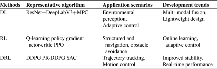
Deep learning is primarily used for state perception and feature extraction, while reinforcement learning focuses on policy optimization in dynamic environments. Deep reinforcement learning integrates perception and decision-making into a unified control framework. Recent studies show a clear trend toward tighter integration of model-based and data-driven methods, along with increased emphasis on sim-to-real transfer and validation. The overall research trends are summarized in Table VI.
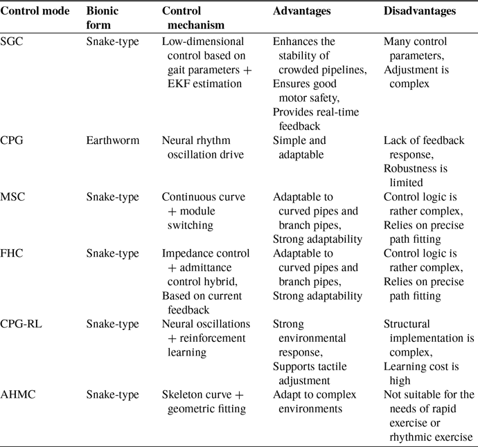
Comparison of characteristics and applicability analysis of bionic control methods.

Table VI. Long description
A table comparing characteristics and applicability of bionic control methods. The table has five rows and three columns. The columns are labeled Methods, Advantages, and Application scenarios. Row 1: Methods, PID; Advantages, The control structure is simple, Strong real-time performance, Suitable for basic speed or attitude control; Application scenarios, Scenarios for basic speed regulation and attitude maintenance of pipeline robots. Row 2: Methods, PID-PSO; Advantages, Automatically optimize control parameters, Enhance system response speed and stability, Strong anti-interference ability; Application scenarios, Adsorptions/maintenance type pipeline robot, Prevention and control for driving, Getting stuck in complex environments. Row 3: Methods, PID-FLC; Advantages, Handle complex multi-variable environments, Enhance the attitude stability of pipe bending navigation; Application scenarios, Tracked-type/spiral pipe robot. Row 4: Methods, PID-LQR; Advantages, LQR stabilizes the attitude, PID regulates the speed, Ensure the overall balance control in the under-drive system; Application scenarios, Large-diameter pipes, Focus on stable driving and posture accuracy. Row 5: Methods, PID-SMPC; Advantages, Sliding mode control enhances robustness, Improves the performance of PID under modeling errors; Application scenarios, Complex pipelines with significant vibration or high uncertainty.
3.7. Bionic motion control methods
Researchers have developed morphology-specific control strategies for different types of biomimetic pipeline robots. Rollinson et al. [Reference Rollinson and Choset110] proposed a control framework that combines gait-parameter-driven locomotion with extended Kalman filter (EKF) estimation. The forward motion of a snake robot is decomposed into finite-state gaits, while the EKF estimates the current gait phase online. This approach enables adaptive contact response without external force or torque sensors. The method is lightweight and computationally efficient, making it suitable for narrow or deformable pipelines. However, its performance is sensitive to initial modeling and filter parameter tuning, and its adaptability degrades in highly unstructured environments. Zhang et al. [Reference Zhang, Pan, Lam, Yan and Li111] developed a soft peristaltic pipeline robot controlled by a multi-node CPG network based on Matsuoka oscillators. The network coordinates multiple pneumatic actuators to inflate and deflate sequentially, producing earthworm-like locomotion. The control structure is simple and rhythmically stable, making it effective in straight or variable-diameter pipes. Nevertheless, conventional CPG control is inherently open-loop and lacks robustness to external disturbances, limiting its performance in obstacle-dense or dynamically changing environments. Liu et al. [Reference Liu, Onal and Fu112] introduced a CPG-RL control architecture that integrates reinforcement learning into the CPG framework. Reinforcement learning dynamically tunes CPG rhythmic parameters, while a local reflex neural feedback network enables real-time modulation based on contact force sensing. Inspired by spinal reflex mechanisms in snakes, this system significantly improves adaptability and robustness in complex and unstructured environments. Sawabe et al. [Reference Sawabe, Nakajima, Tanaka, Tanaka and Matsuno113] presented a modular wheeled snake robot capable of reconfiguring its morphology according to pipeline geometry. By combining active differential wheel propulsion with continuous curvature path-tracking algorithms, the robot achieves stable motion in straight pipes, bends, and branch sections. Although suitable for inspection in industrial pipelines with varying structures, the approach demands high trajectory-fitting accuracy and precise module-switching logic, resulting in increased control complexity and parameter-tuning effort. Wang et al. [Reference Yongdong and Kamegawa114] proposed a hybrid PD-impedance-admittance control framework for pipeline-adaptive snake robots. The inner loop employs PD control for accurate joint tracking, while the outer loop integrates impedance and admittance control to model dynamic interaction with the pipe wall. This design enables real-time disturbance response. However, the framework involves complex parameter design and lacks self-learning capability, limiting its effectiveness in unknown or rapidly changing environments. Tatsuya et al. [Reference Takemori, Tanaka and Matsuno62] developed an adaptive helical locomotion strategy for snake robots to address geometric matching and path tracking in pipelines with irregular cross-sections. The method does not rely on predefined rhythmic controllers or reference trajectories. Instead, it computes the robot’s structural state in real time and adjusts joint phases and postures along a helical path to maintain wall contact. Despite its geometric adaptability, the approach requires high-dimensional multi-DOF model computation, which constrains response speed in fast dynamic scenarios.
In summary, current bioinspired control methods for pipeline robots encompass CPG, CPG-RL hybrid control, backbone curve fitting, gait-based compliant control, and hybrid force–position control. These approaches differ significantly in terms of rhythmic generation, joint coordination, environmental robustness, and dependence on model fidelity, as summarized in Table VII. Future developments in bioinspired control are expected to emphasize locally driven sensing, structural–control integration, and the incorporation of neuro-inspired feedback mechanisms for enhanced adaptability and autonomy.
Comparison of characteristics and applicability analysis of bionic control methods.

Table VII. Long description
Panel A: Table with columns labeled Methods, Representative algorithm, Application scenarios, and Development trends. The Methods column lists DL, RL, and DRL. The Representative algorithm column lists ResNet+DeepLabV3+MPC, Q-learning policy gradient actor-critic PPO, and DDPG PR-DDPG SAC. The Application scenarios column lists Environmental perception, Adaptive control, Structured and navigation, obstacle avoidance, and Trajectory tracking, Motion control. The Development trends column lists Multi-modal fusion, Lightweight design, Online learning, adaptive control, and Improved stability, Real-time performance.
4. Key technologies and challenges of pipeline robots
Despite significant advancements in the design, control algorithms, and physical prototyping of pipeline robots, most efforts remain confined to laboratory settings or simulation environments, with limited application in complex, real-world industrial pipeline systems. In actual scenarios – characterized by diverse geometries, intricate routing, and severe internal disturbances – existing robotic platforms continue to face critical challenges in terms of adaptability, operational robustness, and autonomous capability.
Key technological bottlenecks include:
-
• Highly adaptable morphological integration for navigation in complex pipeline topologies.
-
• Robust localization and navigation in GNSS-denied environments.
-
• Reliable communication under strong electromagnetic shielding.
-
• Advanced autonomous control strategies for dynamic and unstructured conditions.
Bridging these gaps is essential for transitioning pipeline robots from proof-of-concept to large-scale industrial deployment.
4.1. Energy efficiency optimization technologies for pipeline robot systems
Pipeline robots obtain energy mainly through two approaches: tethered and untethered power supplies. Tethered robots are connected to external equipment via physical cables that provide both electrical power and data transmission. This approach offers a stable energy supply and a high communication bandwidth, making it suitable for real-time control and large-volume data transfer. However, cable length restricts the operational range. In complex pipeline environments, cables may also experience friction or entanglement with pipe walls, increasing locomotion resistance and control complexity. Untethered robots, in contrast, offer greater mobility and autonomy, enabling exploration of more complex pipeline networks. Their operation, however, relies on onboard batteries, and limited battery capacity significantly constrains endurance and inspection range. Improving the energy efficiency of untethered pipeline robots, therefore, remains a critical challenge. To achieve long-duration and long-distance inspection, researchers have proposed various optimization strategies at the hardware, control, and system levels. Energy consumption characteristics vary significantly among different locomotion configurations, and Table VIII compares the energy profiles of representative robot types.
Comparison of energy consumption characteristics of typical pipeline robots.

Table VIII. Long description
A table comparing energy consumption characteristics of pipeline robots. The table has six rows and five columns. The columns are labeled Control mode, Bionic form, Control mechanism, Advantages, and Disadvantages. Row 1: Control mode, S G C; Bionic form, Snake-type; Control mechanism, Low-dimensional control based on gait parameters + E K F estimation; Advantages, Enhances the stability of crowded pipelines, Ensures good motor safety, Provides real-time feedback; Disadvantages, Many control parameters, Adjustment is complex. Row 2: Control mode, C P G; Bionic form, Earthworm; Control mechanism, Neural rhythm oscillation drive; Advantages, Simple and adaptable; Disadvantages, Lack of feedback response, Robustness is limited. Row 3: Control mode, M S C; Bionic form, Snake-type; Control mechanism, Continuous curve + module switching; Advantages, Adaptable to curved pipes and branch pipes, Strong adaptability; Disadvantages, Control logic is rather complex, Relies on precise path fitting. Row 4: Control mode, F H C; Bionic form, Snake-type; Control mechanism, Impedance control + admittance control hybrid, Based on current feedback; Advantages, Adaptable to curved pipes and branch pipes, Strong adaptability; Disadvantages, Control logic is rather complex, Relies on precise path fitting. Row 5: Control mode, C P G-R L; Bionic form, Snake-type; Control mechanism, Neural oscillations + reinforcement learning; Advantages, Strong environmental response, Supports tactile adjustment; Disadvantages, Structural implementation is complex, Learning cost is high. Row 6: Control mode, A H M C; Bionic form, Snake-type; Control mechanism, Skeleton curve + geometric fitting; Advantages, Adapt to complex environments; Disadvantages, Not suitable for the needs of rapid exercise or rhythmic exercise.
As shown in the table, robots with simpler mechanical structures and fewer actuators generally exhibit better inherent energy efficiency. In contrast, complex mechanisms or structures with high friction tend to incur greater energy consumption. To address the limited endurance of untethered robots, researchers have proposed optimization strategies in three major aspects: structural design, motion control, and system architecture.
From a structural design perspective, Liu et al. [Reference Liu, He, Zhang, Cao, Zheng and Dai121] developed a large-diameter tracked-type pipeline robot in which electric push rods independently regulate the wall-contact force of each track module. Differential control is employed to actively correct robot posture, ensuring optimal contact conditions during long-distance travel and preventing additional energy losses caused by uneven friction or posture deviation. In addition, flexible robots using lightweight materials or soft structures can reduce energy consumption at the source. Their inherent passive adaptability allows them to traverse complex pipelines without becoming stuck, thereby avoiding unnecessary energy expenditure. For example, Wijesundara et al. [Reference Wijesundara, Xu, He, Jain, Malik and Jafari119] proposed a pneumatically driven soft pipeline robot with a continuous flipping locomotion mechanism. Simulation results indicate strong potential for high energy efficiency.
From the perspective of motion control, the Shenyang Institute of Automation, Chinese Academy of Sciences [Reference Li, Ma, Lyu, Jiang and Liu117] proposed an energy-optimal speed control strategy for spiral-driven pipeline robots that accounts for actuator characteristics. A DC motor model incorporating equivalent loss resistance was established, and the optimal speed trajectory was obtained by minimizing total input energy. Simulation and experimental results demonstrate that this approach utilizes limited battery energy more efficiently than conventional control methods.
From the system architecture perspective, Hong et al. [Reference Hong, Wu, Wang, Ren, Wang, Liu, Hu and Sitti120] developed a novel wireless micro-robot that converts the kinetic energy of internal pipeline fluid into mechanical propulsion using an onboard impeller. This design enables autonomous energy harvesting and offers a promising solution for continuous inspection in oil-filled or gas-filled pipelines. Yan et al. [Reference Yan, Zhao, Miao and Gao122] applied a multi-objective particle swarm optimization method to plan robot trajectories. The optimal path was selected using an analytic hierarchy process-minimum fuzzy entropy (AHP-MFE) method, reducing energy consumption by 17.5% and demonstrating the significant potential of trajectory optimization for energy savings. For tethered robots, Sato et al. [Reference Sato, Uchiyama, Ito, Sawahashi and Nakamura123] proposed a distributed multi-robot deployment strategy in which multiple robots share traction forces along the cable. This arrangement reduces cable friction losses and effectively extends the operational distance.
Comparative analysis of the structural and control design of pipeline robots for complex pipeline configurations.

Table IX. Long description
The table has four rows and three columns. The columns are labeled Reference source, Robot type, and Energy consumption characteristics. Row 1: Wu et al., Tracked-type, High energy consumption. Row 2: Chang et al., Wheel-driven, Energy consumption can be optimized. Row 3: Li et al., Screw-driven, Complex control/high energy consumption. Row 4: Murata et al., Snake-type, Low speed/complex energy consumption characteristics. Row 5: Wijesundara et al., Inchorm type, Energy autonomous. Row 6: Hong et al., PIG, Energy autonomous.
4.2. Comprehensive technology for highly adaptable configuration of complex pipe networks
The intricate geometries and topological complexity of industrial pipelines impose stringent requirements on the structural adaptability of in-pipe robotic systems. To ensure the effective operation of perception and control modules, robots must demonstrate high maneuverability, mechanical compliance, and task stability at the hardware level. The primary challenge is navigating curved and vertical segments. Robots are susceptible to structural interference (e.g., wall collisions) and kinematic singularities when traversing bends. Wall contact can cause mechanical damage or jamming, while entering a singular configuration may result in complete actuation failure, interrupting propulsion. In vertical sections – particularly those complicated by sediment buildup, slippery surfaces, or insufficient adhesion – robots must provide high driving forces and maintain stable wall press support to ensure reliable climbing and controlled descent. The second critical aspect is adaptability to variations in pipe diameter and cross-sectional shape. Robots must incorporate self-adjusting structural mechanisms that expand or contract in response to environmental changes, ensuring continuous contact and stable locomotion across nonuniform geometries. Third, mechanical durability and environmental resilience are essential. Pipeline robots must operate reliably under extreme conditions, including elevated temperature, pressure, and submersion. Enhancing mechanical robustness and system survivability is critical for industrial viability. Based on the findings summarized in Table IX, we propose the following design strategies:
-
• Morphological optimization: Architectures should transition from monolithic to modular, from non-pressing to wall-pressing, and from passive to actively adaptive configurations. Modular structures mitigate singularity risk, wall-pressing enhances vertical traction, and active deformation improves environmental conformity.
-
• Comprehensive dynamic modeling: Full-domain dynamic models are needed to represent bend-induced forces, frictional losses, sludge interference, and actuator slippage. Simulating diameter adaptation and kinematic smoothness is crucial for tuning predictive behavior.
-
• Environmental hardening: Robots should incorporate waterproofing, thermal shielding, and chemical resistance, ensuring reliable operation under harsh industrial conditions.
4.3. Navigation and positioning technology in satellite rejection environments
Accurate localization and navigation are fundamental to autonomous pipeline operations. Traditional approaches predominantly rely on Global Navigation Satellite Systems (GNSS). However, in real-world pipeline applications, GNSS-based methods face severe limitations due to structural occlusion, significant burial depth, and signal attenuation caused by the complex shielding characteristics of surrounding materials. These conditions result in frequent signal degradation, multipath interference, and even complete localization failure. Additionally, the internal pipe environment lacks distinct visual landmarks, has low-light conditions, and exhibits semantic ambiguity, all of which impair perception robustness. Kahnamouel et al. [Reference Kahnamouei and Moallem2] conducted a comprehensive review of current localization techniques for in-pipe robotics. Building upon that foundation, this study identifies three main technical pathways for localization in a GNSS-denied environment:
-
• Multi-source sensor fusion for enhanced perception
-
Single-sensor approaches often fall short under complex pipe conditions. A multisensor fusion framework – integrating LiDAR, RGB cameras, IMU, wheel odometry, and contact sensors – is essential for robust state estimation and environmental modeling. Incorporating prior information (e.g., pipe material, layout, temperature, gas concentration) enhances situational awareness and anomaly detection, improving localization performance in perception-deficient areas.
-
• Graph-based SLAM and in-pipe topological mapping
-
In the absence of absolute positioning, SLAM (Simultaneous Localization and Mapping) provides a viable alternative. Visual- or LiDAR-inertial odometry systems can incrementally build topological maps and identify key structural features. Pipe-specific semantic SLAM frameworks should be employed to extract pipe-specific features such as T-junctions, elbows, and corrosion zones. Accuracy can be further improved by deploying visual landmarks or RFID beacons for high-confidence corrections.
-
• Deep learning–enhanced visual localization
-
Deep learning models, especially CNN and Transformer, allow for robust feature abstraction and multimodal fusion. This approach allows for robust defect detection and accurate path estimation, even under extreme conditions. Deep networks can also support task-driven models for object detection and classification, assessing defect types and severity, and facilitating semantic map updates and autonomous path planning. Lightweight network architectures, optimized feature selection, and real-time inference strategies are essential for high-performance deployment under resource-constrained conditions.
Multisensor fusion approaches provide high stability and precision but often come with greater computational overhead. SLAM-based methods are flexible and ideal for dynamic map construction, but their robustness may decrease in rapidly changing environments. Deep learning-assisted localization achieves state-of-the-art accuracy in feature-rich scenarios, especially for defect detection and scene understanding, though its high algorithmic complexity and deployment cost remain challenges.
4.4. Communication technologies in highly shielded confined spaces
Pipelines represent a typical, highly shielded, and elongated confined environment. Metal materials, high curvature, and underground deployment severely challenge conventional communication technologies. Wired communication offers high reliability and strong interference resistance, but its complex structure, limited flexibility, high deployment cost, and length constraints make it unsuitable for long-distance communication in complex pipeline networks. As a result, recent research has increasingly shifted toward more robust wireless communication solutions. However, wireless channels inside pipelines are highly complex. Electromagnetic waves experience severe attenuation in metal pipes, and the signal attenuation of conventional Wi-Fi and Bluetooth can exceed 20 dB/m in enclosed metal pipelines [Reference Owojaiye and Yichuang128], while relay deployment is costly and difficult to scale for full coverage. These constraints impose stricter requirements on system robustness, network self-organization, and communication reliability for remote control, condition monitoring, and data transmission. To address these challenges, several communication strategies and integrated system solutions have been proposed. Wu et al. [Reference Wu, Chatzigeorgiou, Youcef-Toumi and Ben-Mansour129] proposed a leaky feeder cable deployed along the pipeline to form a continuous communication link, reducing signal attenuation and improving reliability for long-distance inspection tasks. Wu et al. [Reference Wu, Mittmann, Winston and Youcef-Toumi130] further optimized the wireless communication protocol for pipeline robots by introducing a multi-hop network structure, improving signal transmission efficiency and node localization accuracy in complex topologies. Tan et al. [Reference Tan, Sun, Wang and Sun131] developed an extremely low-frequency electromagnetic communication system capable of penetrating metal pipe walls and resisting electromagnetic interference, enabling stable communication in complex environments. Kazeminasab et al. [Reference Kazeminasab and Banks92] developed the SmartCrawler wireless communication system, integrating mesh networking and magnetic induction communication to support dynamic routing and redundant data links, significantly improving communication robustness. Spandonidis et al. [Reference Spandonidis, Theodoropoulos, Giannopoulos, Galiatsatos and Petsa132] combined wireless sensor networks with deep learning for pipeline leak detection and communication optimization, enabling multimodal data fusion and adaptive system performance.
Based on existing studies, communication system design for highly shielded pipeline environments should adopt a combination of strategies: constructing a mesh-network-based redundant communication architecture to improve fault tolerance and maintain network operation under local failures; deploying relay nodes at key locations or on the ground surface to extend coverage and enhance signal penetration; developing refined electromagnetic propagation models based on material properties and environmental parameters to support network deployment and parameter optimization; integrating multiple communication methods, such as extremely low frequency electromagnetic communication, leaky feeder cables, and magnetic induction communication, with adaptive switching based on environmental conditions; and incorporating data compression and edge computing to reduce transmission load and improve remote data processing efficiency, thereby ensuring system stability under high-frequency communication requirements.
4.5. High autonomous intelligent control technology
In structurally intricate and dynamically evolving pipelines, robots must possess a high level of autonomy and intelligent control – capable of completing the entire sense–plan–act loop without external intervention. This is essential for handling environmental uncertainty, variations in topology, and dynamic task requirements in real time. From a theoretical standpoint, the control problem can be modeled as a Markov Decision Process (MDP), requiring a nonlinear mapping from high-dimensional sensory inputs to structured control actions. Due to the infeasibility of hand-coding such mappings, modern systems increasingly rely on reinforcement learning, dynamic programming, and optimal control methods to enable real-time, adaptive behavior.
A notable demonstration of high-level autonomy was achieved by the CSIRO Data61 team during the DARPA Subterranean Challenge (SubT). Their robotic platform autonomously explored and mapped hazardous, unknown underground pipelines, achieving
 $99\%$
accuracy in generating a global 3D map. As schematically shown in Figure 24, this was enabled by a multi-modal sensing architecture, distributed SLAM, and auction-based task coordination [Reference Hudson, Talbot, Cox, Williams, Hines, Pitt, Wood, Frousheger, Surdo, Molnar, Steindl, Wildie, Sa, Kottege, Stepanas, Hernandez, Catt, Docherty, Tidd, Tam, Murrell, Bessell, Hanson, Tychsen-Smith, Suzuki, Overs, Kendoul, Wagner, Palmer, Milani, O’Brien, Jiang, Chen and Arkin133].
The CSIRO system showcases two fundamental innovations: a unified perception framework and a coordinated distributed control mechanism. Each robot was equipped with a CatPack sensor suite – comprising rotating LiDAR and RGB cameras – for full 3D spatial awareness. A decentralized multi-robot SLAM framework allowed each unit to build local maps independently while fusing boundary data to generate a global map collaboratively. Task allocation was governed by an auction-based mechanism, where robots bid for tasks based on computational capacity, communication status, and task priority. Upon task completion, the global map was updated in real time. Communication between robots was implemented through peer-to-peer links, eliminating dependence on a central server and significantly enhancing system resilience and real-time performance.
Architecture diagram of the autonomous control system for pipeline robots of the CSIRO Data61 team.

These results demonstrate the transformational potential of intelligent autonomy for enhancing pipeline robot navigation, perception, and mission execution. To further support large-scale deployment, future development should focus on:
-
• Multi-robot systems and human–robot collaboration
-
Transition from single-agent systems to collaborative swarms that utilize decentralized SLAM and task sharing. Human–robot teaming can enhance flexibility, decision accuracy, and operational safety.
-
• Machine learning–driven adaptive control
-
Integrate deep learning and reinforcement learning into the control pipeline to create closed-loop perception–action systems. Applications include real-time strategy adaptation, resource-aware task scheduling, and environment-driven control tuning.
-
• Edge–cloud collaborative frameworks
-
Deploy edge computing for low-latency feedback and lightweight sensor fusion, while offloading global computation to cloud platforms for data storage, mission analytics, and model updates. This integrated hybrid control architecture supports scalability, mission continuity, and cross-platform knowledge transfer.
4.6. Practical engineering applications of pipeline robots
Pipeline robots have achieved substantial progress in engineering applications across the energy, municipal, extreme-environment, and small-diameter pipeline sectors. Zhang et al. [Reference Zhang, Miao, Yi, Wan, Wang, Zeng and Wang134] developed the RoboChain-I robot, which adopts a modular biomimetic architecture and enables adaptive locomotion within pipe diameters ranging from 175 to 440 mm, reaching an in-pipe speed of 0.4 m/s. On-orbit experiments conducted aboard the China Space Station [Reference Zheng, Wang, Li, Zhao, Jiang, Huang and Ceccarelli17] validated stable operation in straight, curved, and tapered pipes, as well as passive compliance for safety under power-off conditions. Hitesh et al. [Reference Bhardwaj, Shaukat, Barber, Blight, Jackson-Mills, Pickering, Yang, Mohd Sharif, Han, Xin and Richardson135] proposed the Mega-Joey miniature tetherless collaborative robot for autonomous inspection in small pipelines. It operates in pipes larger than 160 mm in diameter and achieves an endurance of 60 minutes. Northumbrian Water in the UK [136] deployed an autonomous inspection robot for continuous sewer monitoring and blockage early warning. The system can patrol several miles of pipeline for up to 30 consecutive days and localize early-stage obstructions in real time. Ahmed et al. [Reference Eltwab and Sameh137] designed a modular autonomous wall-climbing robot for multimodal inspection of oil pipelines, suitable for 150–200 mm diameters, with a speed of 0.25 m/s and a climbing capability of 45
 $^\circ$
. The EU PIPEON project [138] introduced an AI-enabled autonomous maintenance robot for sewer inspection and cleaning, reducing inspection costs and decreasing wastewater overflows by 30%.
Despite these advances, significant technical challenges remain in practical deployment. In perception and localization, wireless signals suffer severe attenuation inside metallic pipelines. Inertial navigation accumulates large errors over long distances. Water, oil, and sludge further degrade sensor accuracy, making precise defect localization difficult. In geometric adaptability, balancing mobility efficiency and passability across large diameter variations remains challenging. Effective solutions for micro-pipelines below 300 mm are still limited. Robots often struggle to traverse T-junctions, U-bends, and vertical segments.
In terms of operational safety and reliability, unexpected blockage may damage the robot or obstruct the pipeline. Fault recovery after long-distance missions is difficult without external intervention. Excessive driving force may also damage the pipe wall. Environmental adaptability presents additional constraints. Water, oil, and corrosive media threaten electronic systems. Deeply buried pipelines and high-temperature environments impose stringent material requirements. Explosive or flammable scenarios demand strict explosion-proof certification, further increasing design complexity.
5. Conclusion
This review presents a comprehensive analysis of the application scenarios and technological evolution of pipeline robots, with a focus on recent advances in locomotion mechanisms and control strategies. Locomotion technologies have evolved from passive-driven systems to actively powered configurations, including wheel-driven, tracked-type, foot-driven, and bioinspired designs such as snake-type, inchworm-type, and screw-driven robots. These developments have culminated in multi-modal hybrid platforms capable of coordinated and adaptive movement across a wide range of pipeline environments. The current trend emphasizes high mobility, modularization, and morphological adaptability. Enhanced controllability and environmental compliance now rely on multi-degree-of-freedom structures and precise dynamic modeling. To meet the demands of unstructured and variable pipeline networks, structural designs are increasingly tailored and often integrate multiple locomotion modes within a single robotic platform to ensure cross-scenario versatility. In terms of control, traditional methods such as PID and differential control are gradually being superseded by intelligent approaches, including MPC, Dynamic Coordinated Control (DCC), FLC, CPG, and reinforcement learning. Highly autonomous systems are beginning to incorporate human–robot interaction, distributed task planning, and swarm intelligence to handle complex trajectories, dynamic disturbances, and unpredictable task transitions in real time.
Despite these advancements, real-world deployment still faces several critical challenges: adaptability to complex and branched pipeline networks, localization in GNSS-denied environments, robust communication under electromagnetic shielding, and high-level autonomous decision-making. In response, we propose a five-dimensional integrated system architecture that unifies structural adaptability, perceptual intelligence, autonomous control, reliable communication, and energy-efficient operation. Future research should focus on morphable design for enhanced geometric compliance, environment-driven adaptive actuation, intelligent and learning-based control frameworks, collaborative multi-agent operation, and semantically aware perception systems. These directions are essential for bridging the gap between experimental validation and large-scale engineering deployment, enabling pipeline robots to operate reliably in real-world industrial scenarios.
Author contributions
Cheng Liu: Conceptualization, methodology, literature search, and writing-original draft; Ke Niu: Literature screening, literature collection, data curation, visualization, and writing-original draft; Chengrong Kuang: Literature analysis and writing-review & editing; Xiuyan Li: Project administration, supervision, and writing-review & editing.
Financial support
This work received no specific grant from any funding agency, commercial or not-for-profit sectors.
Competing interests
The authors declare that they have no known competing financial interests or personal relationships that could have appeared to influence the work reported in this paper.
Ethical approval
Not applicable.


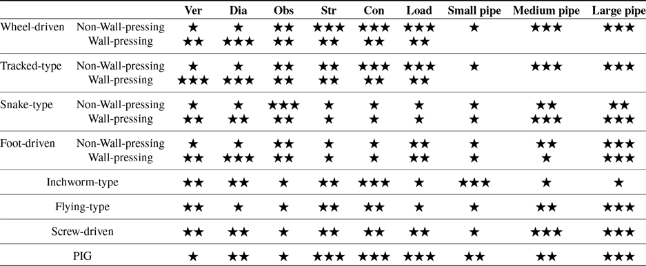
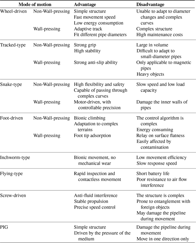


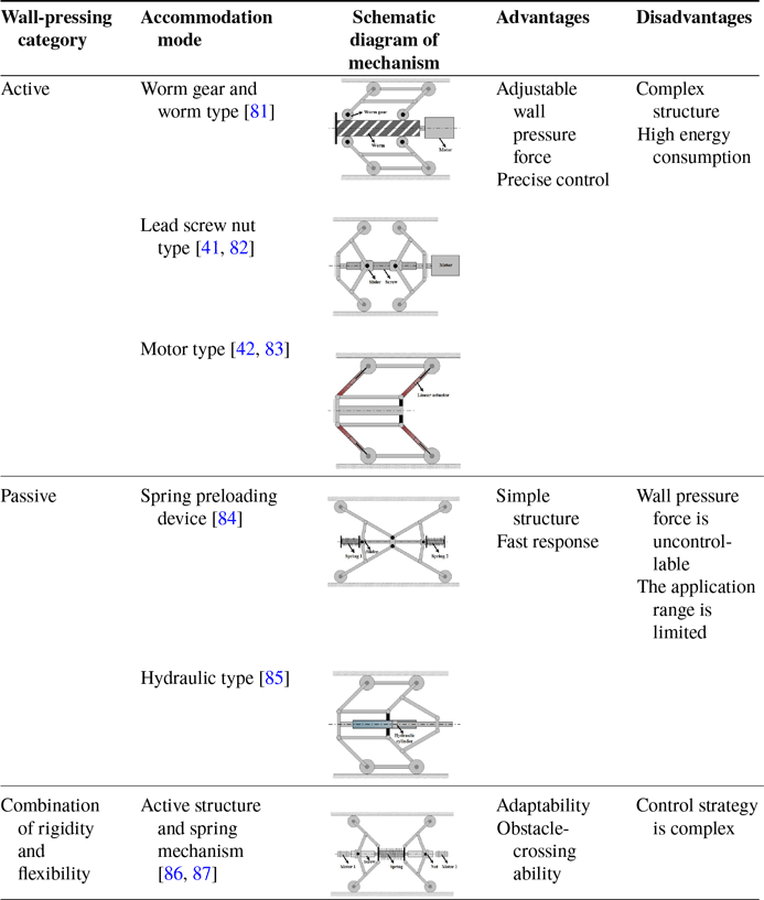
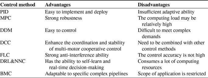
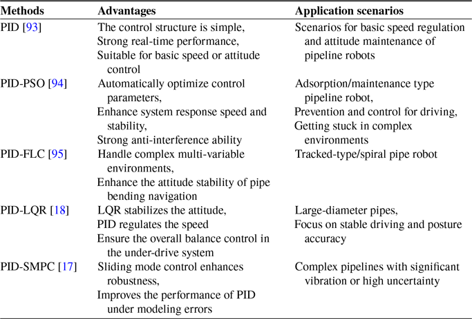


 ∘