


1. Introduction
In recent years, due to industrial and residential applications, the demand for the development and utilisation of artificial marine structures nearshore and offshore has increased significantly (Lamas-Pardo, Iglesias & Carral Reference Lamas-Pardo, Iglesias and Carral2015). Among the wide variety of nearshore and offshore artificial structures, some can be identified as floating porous elastic plates with small draught relative to their horizontal dimensions, e.g. floating flexible breakwaters (Michailides & Angelides Reference Michailides and Angelides2012), artificial floating vegetation fields (Kamble & Patil Reference Kamble and Patil2012) and extensive aquaculture farms (Wang & Tay Reference Wang and Tay2011). The floating elastic plate model is the basis for understanding this process (Squire Reference Squire2020). In particular, the scattering characteristics are best analysed by considering multiple ice floes to account for interactions (Bennetts et al. Reference Bennetts, Peter, Squire and Meylan2010; Montiel, Squire & Bennetts Reference Montiel, Squire and Bennetts2015a, Reference Montiel, Squire and Bennetts2016; Montiel & Squire Reference Montiel and Squire2017). However, these elastic plate scattering models cannot account for the loss of energy, and there are several models which propose that a porous or equivalent layer can account for the observed energy loss (Zhao & Shen Reference Zhao and Shen2018; Sutherland et al. Reference Sutherland, Rabault, Christensen and Jensen2019). These models motivate the study of flexural deformations of floating porous elastic plates subject to water waves and to evaluate carefully the wave-energy dissipation caused by their porosity.
The water-wave scattering of floating elastic plates has been comprehensively investigated by numerous researchers, and there are several reviews that relate to this topic (e.g. Squire Reference Squire2008, Reference Squire2011, Reference Squire2020). To evaluate the interaction of waves with a horizontal floating semi-infinite elastic plate, Sahoo, Yip & Chwang (Reference Sahoo, Yip and Chwang2001) used the analytic representation based on the eigenfunction expansion method of Fox & Squire (Reference Fox and Squire1994), in the context of two-dimensional (2-D) linear potential flow theory. The influence of various edge conditions, i.e. a free edge, a simply supported edge and a built-in edge, on the hydrodynamic behaviour was investigated. The free-edge condition was shown to result in the maximum plate deflection. Squire & Dixon (Reference Squire and Dixon2000) studied wave propagation across a narrow straight-line crack in an infinite thin plate floating on water of infinite depth with a Green's function model. The reflection and transmission coefficients were observed to depend significantly on the wave frequency. Evans & Porter (Reference Evans and Porter2003) provided an explicit solution for the wave scattering of an infinite thin plate with a crack for finite water depth. They obtained a more straightforward approach by splitting the higher-order conditions to be satisfied at the edge of each plate into the sum of even and odd solutions. These models (Squire & Dixon Reference Squire and Dixon2000; Evans & Porter Reference Evans and Porter2003) for the single-crack problem were later extended to an elastic plate with multiple cracks (Squire & Dixon Reference Squire and Dixon2001; Porter & Evans Reference Porter and Evans2006), but where all the plates have identical properties. Then, Kohout et al. (Reference Kohout, Meylan, Sakai, Hanai, Leman and Brossard2007) studied a 2-D fluid covered by a finite number of elastic plates, which were of arbitrary characteristics. Williams & Porter (Reference Williams and Porter2009) introduced an eigenfunction expansion method based on deriving an integral equation, which was then solved using the Galerkin technique, to determine the problem of wave scattering by two semi-infinite plates. These two semi-infinite plates can have different properties, including variable submergence following Archimedes’ principle. A similar problem was later investigated by Zhao & Shen (Reference Zhao and Shen2013) in which the plates were considered to have viscoelastic material properties. More recently, Kalyanaraman et al. (Reference Kalyanaraman, Bennetts, Lamichhane and Meylan2019) considered wave interactions with a land-attached elastic plate of constant thickness and non-zero draught. The solution was found to be strongly influenced by the draught. Koley, Mondal & Sahoo (Reference Koley, Mondal and Sahoo2018) investigated wave scattering of a flexible plate composed of porous materials floating in water of finite and infinite depths employing the Green's function procedure. The porosity was modelled using Darcy's law, and the porous-effect parameter was taken as a complex number to account for both the resistance and inertia effects. The dissipation of the wave power due to structural porosity reduced the wave transmission on the lee side of the plate, which led to the creation of a tranquil zone.
In order to understand the hydroelastic problem of elastic plates floating in ocean waves when the plate length along the crest line of the incident waves is not much larger than the wavelength, three-dimensional effects must be considered. Meylan & Squire (Reference Meylan and Squire1996) studied the behaviour of a solitary, circular, flexible ice floe brought into motion by the action of long-crested sea waves. Two independent methods were developed in their model, i.e. an expansion in the eigenfunctions of a thin circular plate, and the more general method of eigenfunctions used to construct a Green's function for the plate, enabling a check to be carried out on the model. Zilman & Miloh (Reference Zilman and Miloh2000) developed a three-dimensional closed-form solution based on the angular eigenfunction expansion method for water-wave interaction with a circular thin elastic plate floating in shallow water. Their method was based on the roots of the dispersion equation. Since the shallow-water approximation was considered, only three roots in the plate-covered region and one root in open water were required in their model. The potential was matched at the edge of the plate, and the plate boundary conditions were applied to solve the wave scattering problem. Peter, Meylan & Chung (Reference Peter, Meylan and Chung2004) extended the earlier study (Zilman & Miloh Reference Zilman and Miloh2000) to a theoretical solution for a circular elastic plate floating in finite-depth water, i.e. without the restriction of the shallow-water approximation. Therefore, more roots of the dispersion equation for both the plate-covered region and the open-water region were required. The potential throughout the water depth, rather than at a point, was matched and the plate boundary conditions were applied. Since the plate geometry was circular (Zilman & Miloh Reference Zilman and Miloh2000; Peter et al. Reference Peter, Meylan and Chung2004), the angular eigenfunctions can be decoupled. Hence each angular eigenfunction can be solved separately, and the matching problem becomes 2-D, similar to the method of Sahoo et al. (Reference Sahoo, Yip and Chwang2001) and others. Montiel et al. (Reference Montiel, Bennetts, Squire, Bonnefoy and Ferrant2013a,Reference Montiel, Bennetts, Squire, Bonnefoy and Ferrantb) reported a series of wave basin experiments and analytical simulations that investigated the flexural response of one or two circular floating thin elastic plates to monochromatic waves. The plate–plate hydrodynamic interactions were observed in the two-plate tests. Recently, Meylan, Bennetts & Peter (Reference Meylan, Bennetts and Peter2017) carried out an analytical study on wave scattering by a circular floating porous elastic plate. A quantity proportional to the energy dissipated by the plate due to porosity was calculated by integrating the far-field amplitude functions, but the exact dissipated power was not given. The hydroelastic characteristics of elastic plates in other situations, such as a horizontal elastic plate submerged in the water (Mahmood-Ul-Hassan, Meylan & Peter Reference Mahmood-Ul-Hassan, Meylan and Peter2009; Mohapatra, Sahoo & Guedes Soares Reference Mohapatra, Sahoo and Guedes Soares2018a), a submerged horizontal flexible porous plate (Behera & Sahoo Reference Behera and Sahoo2015; Renzi Reference Renzi2016; Mohapatra, Sahoo & Guedes Soares Reference Mohapatra, Sahoo and Guedes Soares2018b), submerged multilayer horizontal porous plate breakwaters (Fang, Xiao & Peng Reference Fang, Xiao and Peng2017), multiple floating elastic plates with a body floating or submerged in the water (Li, Wu & Ji Reference Li, Wu and Ji2018a,Reference Li, Wu and Jib) have also been investigated.
The methods used to calculate the scattering from a single body can be extended to multiple bodies, but there is a rapid growth in the computational cost. For this reason, methods based on a scattering matrix (or diffraction transfer matrix) have been developed to solve for multiple floating bodies, using the theory of Kagemoto & Yue (Reference Kagemoto and Yue1986). This has been particularly true for the case of floating elastic plates used to model ice floes. The first application of this theory was by Peter & Meylan (Reference Peter and Meylan2004) and this remains the only application of the theory to ice floes where they were not assumed circular. The circular floe case has been extended in a number of steps, first by considering arrays (Peter & Meylan Reference Peter and Meylan2009; Bennetts et al. Reference Bennetts, Peter, Squire and Meylan2010) and then to random layers using a quasi-2-D representation (Montiel et al. Reference Montiel, Squire and Bennetts2015a, Reference Montiel, Squire and Bennetts2016; Montiel & Squire Reference Montiel and Squire2017).
Although water-wave interaction with floating elastic plates has been widely studied, most of these plates were non-porous. Until now only a few research works on porous elastic plates have been reported, among which the investigation carried out by Koley et al. (Reference Koley, Mondal and Sahoo2018), Meylan et al. (Reference Meylan, Bennetts and Peter2017) and Zheng et al. (Reference Zheng, Meylan, Fan, Greaves and Iglesias2020) was focused on a single porous elastic plate. For an array of such porous elastic plates, especially with the individual plates deployed close to one another, the hydrodynamic interaction between them can significantly influence their responses. To the best of the authors’ knowledge, the hydrodynamic interaction between multiple floating porous elastic plates has not been investigated yet. In this paper, a theoretical model is developed based on linear potential flow theory and an eigenfunction matching method to investigate wave scattering by multiple circular floating porous elastic plates with three different types of edge conditions, i.e. free edge, simply supported edge and clamped edge. Two methods for evaluating the exact power dissipated by the array of porous plates are proposed.
The rest of this paper is organised as follows. Section 2 outlines the mathematical model for wave scattering problem. Section 3 presents the theoretical solutions of spatial velocity potentials in the water domain. The methods for evaluating the scattered far-field amplitude function and power dissipation are supplied in § 4. Validation of the present theoretical model is presented in § 5. The validated model is then applied to carry out a multiparameter study, the results of which can be found in § 6. Finally, conclusions are outlined in § 7.
2. Mathematical model
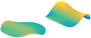
The scattering problem of an array of circular floating porous elastic plates is considered (figure 1). The water domain is divided into two parts, (a) interior region, i.e. the region beneath each plate and (b) the exterior region, i.e. the remainder extending towards infinite distance horizontally. A Cartesian coordinate system  $Oxyz$ is applied to describe the wave scattering problem with
 $z=0$ at the mean water surface and
 $Oz$ pointing upwards. Here,
 $N$ local cylindrical coordinate systems
 $O_nr_n\theta _nz$ for
 $n= 1,2,3,\ldots ,N$ are also introduced corresponding to the
 $n$th plate (see figure 1b). In addition, one more cylindrical coordinate system
 $Or_0\theta _0z$ (not plotted in figure 1) is defined with its origin coinciding with the Cartesian coordinate system. The mean wetted surface of the
 $n$th plate is denoted by
 $\Omega _n$.
Schematic of an array of circular floating porous elastic plates: (a) side view; (b) plan view.

An array of circular porous elastic plates are set in motion by a plane incident wave. The water is assumed to be homogeneous, inviscid and incompressible, and its motion irrotational and time harmonic with a prescribed angular frequency  $\omega$. The velocity potential in the fluid domain can be expressed as
 $\mathrm {Re}[\phi (x,y,z)\,\mathrm e^{-\mathrm i\omega t}]$, where
 $\phi$ is the complex spatial velocity potential,
 $\mathrm {i}$ denotes the imaginary unit and
 $t$ is the time.
The spatial velocity potential  $\phi$ is a solution of the governing equations
 \begin{equation} (\partial_x^{2}+\partial_y^{2}+\partial_z^{2})\phi=0 \quad \mbox{in the fluid domain} \end{equation}
with
 \begin{equation} \partial_z\phi=0, \quad \mbox{on}\ z={-}h \end{equation}
and
 \begin{equation} -\omega^{2}\phi+g\partial_z\phi=0,\quad \mbox{on}\ z=0 \end{equation}
at the water surface of the exterior region.
The floating porous elastic plate is modelled as a thin plate of constant thickness and shallow draft, which is assumed to be in contact with the water at all times following Meylan (Reference Meylan2002). Kirchhoff–Love thin-plate theory, modified to include porosity, is used to model the plate motions. The velocity potential is coupled to the plate displacement function via kinematic and dynamic conditions, respectively,
 \begin{equation} \partial_z\phi={-}\mathrm i\omega\eta^{(n)}+\mathrm ic\phi, \quad g[\chi\mathit\Delta^{2}+1-(\omega^{2}/g)\gamma]\eta^{(n)}-\mathrm i\omega\phi=0, \quad \mbox{for }\Omega_n,\end{equation}
where  $\eta ^{(n)}$ denotes the complex vertical displacement of the lower surface of the
 $n$th plate;
 $g$ represents the acceleration of gravity;
 $c=\omega K\rho /(\mu h)$ denotes the porosity parameter, in which
 $K$ represents the permeability of the plate,
 $\rho$ and
 $\mu$ are the density and dynamic viscosity of water, respectively;
 $\gamma$ and
 $\chi$ denote the mass per unit area and the flexural rigidity of the plate, respectively, scaled with respect to the water density;
 ${\rm \Delta}$ is the Laplacian operator in the horizontal plane. With the employment of the Laplace equation as given in (2.1), the kinematic and dynamic conditions as given in (2.4a,b) can be combined into
 \begin{equation} (\omega^{2}/g)\phi=[\chi\partial_z^{4}+1-(\omega^{2}/g)\gamma](\partial_z-\mathrm ic)\phi. \end{equation}
Additionally, in the far-field horizontally, the scattered wave potential,  $\phi _S=\phi -\phi _I$, where
 $\phi _I$ is the velocity potential of the undisturbed incident waves whose expression will be given in § 3, is subject to the Sommerfeld radiation condition.
The boundary conditions at the edge of each plate should be satisfied as well, which are dependent on the type of plate edge. In this paper, three different edge types, i.e. a clamped edge, a simply supported edge and a free edge, are considered.
For a clamped edge, both displacement and slope vanish at the edge, providing
 \begin{equation} \eta^{(n)}=0 \quad \mbox{and}\quad \partial_n\eta^{(n)}=0, \end{equation}
where  $\eta ^{(n)}$ can be expressed in terms of
 $\phi$ by using the first component of (2.4a,b) and
 $\partial _n$ represents the derivative operator corresponding to the normal vector on the edge
 $\vec {n}=(\cos {\alpha _n},\sin {\alpha _n})$, in which
 $\alpha _n$ is a function of the parameter
 $s$ defining locations on the boundary of the
 $n$th plate (Meylan et al. Reference Meylan, Bennetts and Peter2017).
For a simply supported edge, both displacement and moment vanish at the edge, providing
 \begin{equation} \eta^{(n)}=0\quad \mbox{and}\quad F_M^{(n)}=0, \end{equation}
where
 \begin{equation} F_M^{(n)}={\rm \Delta}\eta^{(n)}-(1-\upsilon)\left(\partial_s^{2}\eta^{(n)}+ \frac{\mathrm d\alpha_n}{\mathrm ds}\partial_n\eta^{(n)}\right)= \frac{\partial^{2}\eta^{(n)}}{\partial r_n^{2}}+\frac{\upsilon}{R_n^{2}} \frac{\partial^{2}\eta^{(n)}}{\partial\theta_n^{2}}+\frac{\upsilon}{R_n}\frac{\partial\eta^{(n)}}{\partial r_n}, \end{equation}
in which  $\upsilon$ denotes the Poisson ratio,
 $\partial _s$ represents the derivative operator corresponding to the tangential vector on the plate edge
 $\vec {s}=(-\sin {\alpha _n},\cos {\alpha _n})$.
For a free edge, both moment and shearing stress vanish at the edge, providing
 \begin{equation} F_M^{(n)}=0\quad \mbox{and}\quad F_V^{(n)}=0, \end{equation}
where
 \begin{align} F_V^{(n)}&=\partial_n{\rm \Delta}\eta^{(n)}+(1-\upsilon)\partial_s\partial_n\partial_s\eta^{(n)} \nonumber\\ &=\frac{\partial^{3}\eta^{(n)}}{\partial r_n^{3}}+\frac{(2-\upsilon)}{R_n^{2}}\frac{\partial^{3}\eta^{(n)}}{\partial r_n\partial\theta_n^{2}} +\frac{1}{R_n}\frac{\partial^{2}\eta^{(n)}}{\partial r_n^{2}}-\frac{(3-\upsilon)}{R_n^{3}}\frac{\partial^{2}\eta^{(n)}}{\partial\theta_n^{2}} -\frac{1}{R_n^{2}}\frac{\partial\eta^{(n)}}{\partial r_n}. \end{align}
3. Theoretical solution to velocity potentials
The velocity potentials in the exterior region and interior region beneath the  $n$th plate are denoted by
 $\phi _{ext}$ and
 $\phi _{int}^{(n)}$, respectively. Expressions for them are given as follows.
3.1. Exterior region
Here
 \begin{equation} \phi_{ext}=\phi_I+\sum_{n=1}^{N}\sum_{m={-}\infty}^{\infty} \sum_{l=0}^{\infty} A_{m,l}^{(n)}H_m(k_lr_n)Z_l(z)\,\mathrm e^{\mathrm im\theta_n}, \end{equation}
where the accumulative term denotes the scattered wave potential,  $\phi _S$;
 $A_{m,l}^{(n)}$ are the unknown coefficients to be determined;
 $Z_l(z)={\cosh [k_l(z+h)]}/{\cosh (k_lh)}$;
 $k_0\in \mathbb {R}^{+}$ and
 $k_l\in \mathrm i\mathbb {R}^{+}$ for
 $l=1,2,3,\ldots$ support the propagating waves and evanescent waves, respectively, and they are the positive real root and the infinite positive imaginary roots of the dispersion relation for the exterior region
 \begin{equation} \omega^{2}=gk_l\tanh(k_lh); \end{equation}
 $H_m$ is the Hankel function of the first kind of the
 $m$th order;
 $\phi _I$ denotes the undisturbed incident wave velocity potential, which can be expressed as
 \begin{gather} \phi_I (x,y,z)={-}\frac{\mathrm igA}{\omega}Z_0(z)\,\mathrm e^{\mathrm ik(x\cos\beta+y\sin\beta)}, \end{gather}
 \begin{gather}\phi_I (r_n,\theta_n,z)={-}\frac{\mathrm igA}{\omega}Z_0(z)\,\mathrm e^{\mathrm ik(x_n\cos\beta+y_n\sin\beta)}\sum_{m={-}\infty}^{\infty} \mathrm i^{m}\,\mathrm e^{-\mathrm im\beta}J_m(kr_n)\,\mathrm e^{\mathrm im\theta_n}, \end{gather}
where (3.3a) and (3.3b) are written in the general Cartesian coordinate system  $Oxyz$ and the local cylindrical coordinate systems
 $O_nr_n\theta _nz$, respectively, in which
 $J_m$ denotes the Bessel function of the
 $m$th order. The second term on the right-hand side of (3.1), i.e. the accumulation term, represents the scattered wave potential,
 $\phi _S=\phi -\phi _I$, as mentioned in § 2, which is subject to the Sommerfeld radiation condition.
After using Graf's addition theorem for Bessel functions (Abramowitz & Stegun Reference Abramowitz and Stegun1972; Zheng, Zhang & Iglesias Reference Zheng, Zhang and Iglesias2018; Zheng et al. Reference Zheng, Antonini, Zhang, Greaves, Miles and Iglesias2019), (3.1) can be rewritten in the cylindrical coordinates  $O_nr_n\theta _nz$ as
 \begin{align} \phi_{ext}(r_n,\theta_n,z)&=\phi_I+\sum_{m={-}\infty}^{\infty} \sum_{l=0}^{\infty}A_{m,l}^{(n)}H_m(k_lr_n)Z_l(z)\,\mathrm e^{\mathrm im\theta_n} \nonumber\\ &\quad +\sum_{\substack{j=1,\\ {j\neq{n}}}}^{N}\sum_{m={-}\infty}^{\infty} \sum_{l=0}^{\infty} A_{m,l}^{(j)}Z_l(z)\sum_{m^{\prime}={-}\infty}^{\infty}({-}1)^{m^{\prime}}H_{m-m^{\prime}} (k_lR_{n,j})J_{m^{\prime}}(k_lr_n) \nonumber\\ &\quad \times \mathrm e^{\mathrm i(m\alpha_{j,n}-m^{\prime}\alpha_{n,j})}\,\mathrm e^{\mathrm im^{\prime}\theta_n}\quad \text{for}\ r_n<\min_{\substack{j=1, N;\\ {j\neq{n}}}}R_{n,j}. \end{align}
3.2. Interior region
Here
 \begin{equation} \phi_{int}^{(n)}(r_n,\theta_n,z)=\sum_{m={-}\infty}^{\infty}\sum_{l={-}2}^{\infty} B_{m,l}^{(n)} J_m(\kappa_lr_n)Y_l(z)\,\mathrm e^{\mathrm im\theta_n}, \end{equation}
where  $B_{m,l}^{(n)}$ are the unknown coefficients to be determined;
 $Y_l={\cosh [\kappa _l(z+h)]}/{\cosh (\kappa _lh)}$;
 $\kappa _l$ for
 $l=-2, -1, 0, 1, 2,\ldots$ are the roots of the dispersion relation for the interior region
 \begin{equation} [\chi\kappa_l^{4}+1-(\omega^{2}/g)\gamma][\kappa_l\tanh(\kappa_lh)-\mathrm ic]=\omega^{2}/g. \end{equation}
For  $c=0$,
 $\kappa _0\in \mathbb {R}^{+}$ and
 $\kappa _l\in \mathrm i \,\mathbb {R}^{+}$ for
 $l =1, 2, 3, \ldots$ can be obtained, which support the propagating waves and evanescent waves, respectively. The remaining two roots,
 $\kappa _{-2}$ and
 $\kappa _{-1}$, support damped propagating waves, and satisfy
 $\kappa _{-1}\in \mathbb {R}^{+}+\mathrm i\mathbb {R}^{+}$ and
 $\kappa _{-2}=-\kappa _{-1}^{*}$, in which * denotes the complex conjugate. For
 $c\neq 0$, the structure of
 $\kappa _l$ is perturbed. In general, neither pure real nor pure imaginary roots exist, and the symmetry between
 $\kappa _{-2}$ and
 $\kappa _{-1}$ is not valid either (Meylan et al. Reference Meylan, Bennetts and Peter2017). The method to compute them efficiently is given in Meylan et al. (Reference Meylan, Bennetts and Peter2017) and Zheng et al. (Reference Zheng, Meylan, Fan, Greaves and Iglesias2020).
Note that the spatial velocity potentials as given in (3.4) and (3.5) already satisfy all the governing equation and boundary conditions as listed in § 2, except at the plate edges. In addition, continuity of pressure and the radial velocity at the interfaces between the exterior region and interior regions should also be satisfied. These continuity conditions can be expressed as follows.
(i) Continuity of pressure at the boundary
 $r_n=R_n$:
(3.7)\begin{equation} \phi_{ext}\big|_{r_n=R_n}=\phi_{int}^{(n)}\big|_{r_n=R_n}, \quad -h < z < 0. \end{equation}
(ii) Continuity of radial velocity at the boundary
$r_n=R_n$:
(3.8)\begin{equation} \left.\frac{\partial\phi_{ext}}{\partial r_n}\right|_{r_n=R_n}= \left.\frac{\partial\phi_{int}^{(n)}}{\partial r_n}\right|_{r_n=R_n}, \quad -h < z < 0. \end{equation}


The continuity conditions, i.e. (3.7)–(3.8), together with the edge type dependent edge conditions, i.e. (2.6a,b), (2.7a,b) or (2.9a,b), can be used to derive a complex linear matrix equation by using the orthogonality characteristics of  $Z_l(z)$ and
 $\mathrm e^{\mathrm im\theta _n}$, and the eigenfunction-matching method. The unknown coefficients
 $A_{m,l}^{(n)}$ and
 $B_{m,l}^{(n)}$ can then be calculated by solving the complex linear matrix equation. Detailed derivation and calculations for the unknown coefficients are given in appendix A.
4. Far-field coefficients, Kochin functions and wave-power dissipation
We present here two derivations of the wave-power dissipation due to the porosity.
4.1. Wave-power dissipation: direct method
The energy dissipated by the  $N$ plates due to the porosity,
 $P_{diss}$, can be calculated by
 \begin{align} P_{diss}&=\frac{c}{2\rho\omega}\sum_{n=1}^{N}\iint_{\Omega_n}|p|^{2}\,\mathrm ds =\frac{\rho\omega c}{2}\sum_{n=1}^{N}\iint_{\Omega_n}|\phi|^{2}\,\mathrm ds \nonumber\\ &=\frac{\rho\omega c}{2}\sum_{n=1}^{N}\iint_{\Omega_n}\left|\sum_{m={-}\infty}^{\infty} \sum_{l={-}2}^{\infty} B_{m,l}^{(n)}J_m(\kappa_lr_n)\,\mathrm e^{\mathrm im\theta_n}\right|^{2}\mathrm ds, \end{align}
where  $p$ denotes the hydrodynamic pressure under the plates,
 $p=\mathrm i\omega \rho \phi$.
The dimensionless quantity of  $P_{diss}$ can be defined by
 \begin{equation} \eta_{diss}=k P_{diss}/P_{in}, \end{equation}
in which  $P_{in}$ is the incoming wave power per unit width of the wave front given by
 \begin{equation} P_{in}=\frac{\rho gA^{2}}{2}\frac{\omega}{2k}\left(1+\frac{2kh}{\sinh(2kh)}\right). \end{equation}
4.2. Wave-power dissipation: indirect method
We present here another, more general, derivation of the power dissipation identity. In this expression, we use the very general equations of motion which govern a floating elastic plate of arbitrary geometry.
Firstly, let us consider the far-field coefficients and Kochin functions. In the fluid domain, far away from an array of porous elastic plates, only the propagating modes exist in the scattered waves. With the asymptotic forms of  $H_m$ for
 $r_0\rightarrow \infty$,
 \begin{equation} H_m(kr_0)=\sqrt{2/{\rm \pi}}\mathrm e^{-\mathrm i(m{\rm \pi}/2+{\rm \pi}/4)}(kr_0)^{{-}1/2}\,\mathrm e^{\mathrm ikr_0} \quad \mbox{for } r_0\rightarrow \infty, \end{equation}
where  $k$ is employed to represent
 $k_0$ for simplification, the scattered wave potential, i.e. the accumulative term in (3.1), can be rewritten as
 \begin{equation} \phi_S=\sqrt{2/{\rm \pi}}Z_0(z)\sum_{n=1}^{N}\sum_{m={-}\infty}^{\infty} A_{m,0}^{(n)}\,\mathrm e^{-\mathrm i(m{\rm \pi}/2+{\rm \pi}/4)} (kr_n)^{{-}1/2}\,\mathrm e^{\mathrm ikr_n}\,\mathrm e^{\mathrm im\theta_n},\quad r_0\rightarrow \infty, \end{equation}
which can be further expressed in the global polar coordinate system  $O_0r_0\theta _0z$ as
 \begin{align} \phi_S&=\sqrt{2/{\rm \pi}}(kr_0)^{{-}1/2}\,\mathrm e^{\mathrm ikr_0}Z_0(z)\sum_{n=1}^{N}\sum_{m={-}\infty}^{\infty} A_{m,0}^{(n)}\,\mathrm e^{-\mathrm ikR_{0,n}\cos(\alpha_{0,n}-\theta_0)}\,\mathrm e^{-\mathrm i(m{\rm \pi}/2+{\rm \pi}/4)}\, \mathrm e^{\mathrm im\theta_0} \nonumber\\ &=A_R(\theta_0)(kr_0)^{{-}1/2}\,\mathrm e^{\mathrm ikr_0}Z_0(z),\quad r_0\rightarrow \infty, \end{align}
where  $A_R$ is the so-called far-field coefficient that is independent of
 $r_0$ and
 $z$, and can be expressed as
 \begin{equation} A_R(\theta_0)=\sqrt{2/{\rm \pi}}\sum_{n=1}^{N}\sum_{m={-}\infty}^{\infty} A_{m,0}^{(n)}\,\mathrm e^{-\mathrm ikR_{0,n} \cos(\alpha_{0,n}-\theta_0)} \mathrm e^{-\mathrm i(m{\rm \pi}/2+{\rm \pi}/4)}\,\mathrm e^{\mathrm im\theta_0}. \end{equation}
The Kochin function,  $H_R$, which is a scale version of the far-field coefficient, can be obtained from
 $A_R$ as follows (Falnes Reference Falnes2002):
 \begin{align} H_R(\theta_0)&=\sqrt{2{\rm \pi}}\,\mathrm e^{-\mathrm i{\rm \pi}/4}A_R(\theta_0) \nonumber\\ &=2\sum_{n=1}^{N}\sum_{m={-}\infty}^{\infty} A_{m,0}^{(n)}\,\mathrm e^{-\mathrm ikR_{0,n} \cos(\alpha_{0,n}-\theta_0)}(-\mathrm i)^{m+1}\,\mathrm e^{\mathrm im\theta_0}. \end{align}
In the water domain enclosed by  $\Omega _1\cup \Omega _2\cup \cdots \cup \Omega _N\cup \Omega _R$, free water surface and the sea bed, using Green's theorem (Falnes Reference Falnes2002; Fàbregas Flavià & Meylan Reference Fàbregas Flavià and Meylan2019), we have
 \begin{align} & \mathop{{\int\!\!\!\!\!\int}\mkern-21mu {\bigcirc}}\left(\phi\frac{\partial\phi^{*}}{\partial n}-\phi^{*} \frac{\partial\phi}{\partial n}\right)\mathrm ds \nonumber\\ &\quad =\sum_{n=1}^{N}\iint_{\Omega_n}\left(\phi\frac{\partial\phi^{*}}{\partial z}-\phi^{*} \frac{\partial\phi}{\partial z}\right)\mathrm ds+\iint_{\Omega_R} \left(\phi\frac{\partial\phi^{*}}{\partial r}-\phi^{*}\frac{\partial\phi}{\partial r}\right)\mathrm ds=0, \end{align}
where  $\Omega _R$ represents an envisaged vertical cylindrical control surface with its radius denoted by
 $r_0=R_0$, which is large enough to enclose all the plates.
With utilisation of the first component of (2.4a,b), (4.9) can be rewritten as
 \begin{equation} \sum_{n=1}^{N}\iint_{\Omega_n}\left[\mathrm i\omega\left(\phi\eta^{(n)*}+\phi^{*}\eta^{(n)}\right)-2\mathrm ic|\phi|^{2}\right] \,\mathrm ds+\iint_{\Omega_R}\left(\phi\frac{\partial\phi^{*}}{\partial r}-\phi^{*} \frac{\partial\phi}{\partial r}\right)\mathrm ds=0.\end{equation}
We are setting out to show that the accumulation of the terms within the first parentheses in (4.10) vanishes.
The response of the  $n$th plate can be expressed by a series of natural modes of vibration of the plate in vacuo as (Meylan et al. Reference Meylan, Bennetts and Peter2017)
 \begin{equation} \eta^{(n)}\approx\sum_{q=1}^{Q}u_q^{(n)}\eta_q^{(n)},\end{equation}
where the modes  $\eta _q^{(n)}$ satisfy the eigenvalue problem for the biharmonic operator
 \begin{equation} \Delta^{2}\eta_q^{(n)}=\lambda_q\eta_q^{(n)},\end{equation}
together with the edge conditions as given in § 2;  $\eta _q^{(n)}$ are orthogonal for different eigenvalues
 $\lambda _q$, and
 $Q$ denotes the truncated numbers of the infinite modes.
The dynamic motion of the plates can be coupled with the hydrodynamics by
 \begin{equation} \left(\boldsymbol{\mathsf{K}}+\boldsymbol{\mathsf{C}} - \frac{\omega^{2}}{g}\boldsymbol{\mathsf{M}}\right)\boldsymbol u= \mathrm i\omega\rho\iint_{\Omega_{sum}}\phi \boldsymbol n\,\mathrm d s, \end{equation}
where  $\Omega _{sum}=\Omega _1\cup \Omega _2\cup \cdots \cup \Omega _N$,
 $\boldsymbol{\mathsf{K}}$,
 $\boldsymbol{\mathsf{C}}$ and
 $\boldsymbol{\mathsf{M}}$ are
 $(NQ)\times (NQ)$ square matrices that represent stiffness, hydrostatic-restoring and mass matrices, respectively,
 \begin{equation} \boldsymbol{\mathsf{K}}=\bigg\langle\chi\lambda_q\bigg\rangle_{(n-1)Q+q};\quad \boldsymbol{\mathsf{C}}=\boldsymbol{\mathsf{I}};\quad \boldsymbol{\mathsf{M}}=\gamma\boldsymbol{\mathsf{I}}, \end{equation}
in which  $\langle c_i\rangle _j$ denotes a diagonal matrix with diagonal entries
 $c_i$ at the position
 $(j,j)$,
 $\boldsymbol{\mathsf{I}}$ is the identity matrix and
 \begin{equation} \boldsymbol u=\bigg[u_q^{(n)}\bigg]_{(n-1)Q+q},\quad \boldsymbol n=\bigg[\eta_q^{(n)}\bigg]_{(n-1)Q+q},\end{equation}
where  $[c_i]_j$ represents a vector with entries
 $c_i$ at the
 $j$th row.
With the employment of (4.11) and (4.13), it can be proved that
 \begin{align} & \sum_{n=1}^{N}\iint_{\Omega_n}\left(\phi\eta^{(n)*}+\phi^{*}\eta^{(n)}\right)\mathrm ds= \sum_{n=1}^{N}\iint_{\Omega_n}\left(\phi\sum_{q=1}^{Q}u_q^{(n)*}\eta_q^{(n)}+ \phi^{*}\sum_{q=1}^{Q}u_q^{(n)}\eta_q^{(n)}\right)\mathrm ds \nonumber\\ &\quad =\iint_{\Omega_{sum}}\left\{-\phi(\boldsymbol x)\left[\left(\boldsymbol{\mathsf{K}}+\boldsymbol{\mathsf{C}}- \frac{\omega^{2}}{g}\boldsymbol{\mathsf{M}}\right)^{{-}1}\mathrm i\omega\rho\iint_{\Omega_{{sum}}} \phi^{*}(\bar{\boldsymbol x})\boldsymbol n(\bar{\boldsymbol x})\,\mathrm d\bar s\right]^{\mathrm T}\boldsymbol n({\boldsymbol x}) \right. \nonumber\\ &\qquad \left.+\phi^{*}(\boldsymbol x)\left[\left(\boldsymbol{\mathsf{K}}+\boldsymbol{\mathsf{C}}-\frac{\omega^{2}}{g}\boldsymbol{\mathsf{M}}\right)^{{-}1}\mathrm i\omega\rho \iint_{\Omega_{{sum}}}\phi(\bar {\boldsymbol x})\boldsymbol n(\bar{\boldsymbol x})\,\mathrm d\bar s\right]^{\mathrm T} \boldsymbol n(\boldsymbol x)\right\}\mathrm ds \nonumber\\ &\quad =0, \end{align}
where we used the symmetry of the matrix  $(\boldsymbol{\mathsf{K}}+\boldsymbol{\mathsf{C}}-({\omega ^{2}}/{g})\boldsymbol{\mathsf{M}})^{-1}$ and reversed the order of integration.
Therefore, (4.10) reads
 \begin{equation} \sum_{n=1}^{N}\iint_{\Omega_n}\left({-}2\mathrm ic\big|\phi\big|^{2}\right)\mathrm ds+ \iint_{\Omega_R}\left(\phi\frac{\partial\phi^{*}}{\partial r}-\phi^{*}\frac{\partial\phi}{\partial r}\right)\mathrm ds=0, \end{equation}
hence the power dissipation can be expressed as
 \begin{equation} P_{{diss}}=\frac{\rho\omega c}{2}\sum_{n=1}^{N}\iint_{\Omega_n}\big|\phi\big|^{2}\,\mathrm ds= \frac{\rho\omega}{4\mathrm i}\iint_{\Omega_R}\left(\phi\frac{\partial\phi^{*}}{\partial r}-\phi^{*} \frac{\partial\phi}{\partial r}\right)\mathrm ds, \end{equation}
which, from the view of energy identities, presents an approach to evaluate the power dissipation based on the spatial potentials in the exterior region.
When  $r_0=R_0\rightarrow \infty$, (4.18) holds as well with the control surface
 $\Omega _R$ replaced by
 $\Omega _\infty$, i.e.
 $r_0\rightarrow \infty$. An expression for the integral in (4.18) in terms of Kochin functions (Falnes Reference Falnes2002) is
 \begin{align} \iint_{\Omega_\infty}\left(\phi\frac{\partial\phi^{*}}{\partial r_0}-\phi^{*} \frac{\partial\phi}{\partial r_0}\right)\mathrm ds= \frac{2\mathrm iAgD(kh)}{\omega k}\mathrm{Re}[H_R(\beta)]- \frac{\mathrm iD(kh)}{2{\rm \pi} k}\int_0^{2{\rm \pi}}|H_R(\theta_0)|^{2}\,\mathrm d\theta_0, \end{align}
where
 \begin{equation} D(kh)=\left[1+\frac{2kh}{\sinh(2kh)}\right]\tanh(kh). \end{equation}
Therefore, the power dissipated by the array of porous elastic plates can be evaluated by using an indirect method based on Kochin functions
 \begin{equation} P_{{diss}}=\frac{\rho\omega D(kh)}{k}\left(\frac{Ag}{2\omega}\mathrm{Re}[H_R(\beta)]-\frac{1}{8{\rm \pi}} \int_0^{2{\rm \pi}}|H_R(\theta_0)|^{2}\,\mathrm d\theta_0\right). \end{equation}
Compared with the straightforward method, i.e. (4.1), which includes the surface integrals over all the plates with both propagating and evanescent waves considered, the indirect method as given in (4.21) consists of only one angular integral regardless of the number of plates, and uses the propagating waves only to achieve an accurate evaluation of the wave-power dissipation. Moreover, (4.21) is derived without any employment of the ‘circular-shape’ restriction, therefore the indirect method applies to the floating porous elastic plates with non-circular shapes as well. Finally, the existence of two different identities gives a method to check the accuracy of the numerical solution, in much the same way that energy conservation can be used in the case of a floating body which does not dissipate energy.
5. Validation
If the spacing between the porous elastic plates is large, the hydrodynamic interaction between them can be neglected. Therefore the response of every plate will be close to that of the plate in isolation. Figure 2 presents the comparison of the displacements of a circular porous elastic plate in isolation (Meylan et al. Reference Meylan, Bennetts and Peter2017) and a pair of the same plates arranged far away from one another, where  $c$,
 $\chi$ and
 $\gamma$ are non-dimensionalised with respect to the water depth as
 $\bar c=ch$,
 $\bar \chi =\chi /h^{4}$ and
 $\bar \gamma =\gamma /h$, respectively. Additionally, the energy dissipated due to porosity as a function of
 ${\bar c}/N$ is provided in figure 3, where
 $E$ is a quantity proportional to the wave-energy dissipated due to the porosity, which was calculated by integrating the far-field amplitude functions based on a coupled boundary-element and finite element method (Meylan et al. Reference Meylan, Bennetts and Peter2017). The present results agree well with those of Meylan et al. (Reference Meylan, Bennetts and Peter2017) and Zheng et al. (Reference Zheng, Meylan, Fan, Greaves and Iglesias2020).
(a–c) Displacements of a circular plate in isolation (Meylan et al. Reference Meylan, Bennetts and Peter2017), where a typo of the incident wave direction existed (i.e.  $\beta$ was typed as 0 rather than
 ${\rm \pi}$); (d–f) and (g–i) displacements of plate-1 and plate-2 in a pair of plates (present results) at
 $t=0$ for different porosity parameter
 $\bar c=0$, 0.5 and 1.0. (
 $R_1=R_2=R$,
 $x_1=x_2=0$,
 $y_1/R=-y_2/R=50$,
 $R/h=2.0$,
 $\beta ={\rm \pi}$,
 $h\omega ^{2}/g=2.0$ and
 $\bar \chi =\bar \gamma =0.01$, free edge.)

Wave-power dissipation by floating circular plates with a free edge versus the porosity parameter for  $R/h=2.0$,
 $\beta ={\rm \pi}$,
 $h\omega ^{2}/g=2.0$ and
 $\bar \chi =\bar \gamma =0.01$ (lines: present results with
 $N=2$,
 $R_1=R_2=R$,
 $x_1=x_2=0$,
 $y_1/R=-y_2/R=50$; symbols: Zheng et al. (Reference Zheng, Meylan, Fan, Greaves and Iglesias2020) and Meylan et al. (Reference Meylan, Bennetts and Peter2017) with
 $N=1$).

We have also compared our model with the experimental data in the case of non-porous plates. Montiel et al. (Reference Montiel, Bennetts, Squire, Bonnefoy and Ferrant2013a) carried out a series of wave basin experiments on a pair of circular floating elastic plates and observed strong hydrodynamic interaction between them. One of the cases tested by Montiel et al. (Reference Montiel, Bennetts, Squire, Bonnefoy and Ferrant2013a), is plotted in figure 4, where four motion tracking markers were placed on each plate. Figure 5 illustrates the theoretical and experimental deflection of the four markers for the two plates. The results show that the present conceptual model can be used to predict the response of the two elastic plates accurately and that it provides insights into the interaction between the two plates.
Deployment of two circular elastic plates. Four markers are labelled in each plate for reference. ( $\bar c=0$,
 $\bar \chi =3.55\times 10^{-4}$,
 $\bar \gamma =2.79\times 10^{-3}$, free edge.)

Deflection of (a) marker 1; (b) marker 2; (c) marker 3 and (d) marker 4 for the two-plate arrangement as given in figure 4, as a function of frequency. Each figure contains the present theoretical results and the experimental data (Montiel et al. Reference Montiel, Bennetts, Squire, Bonnefoy and Ferrant2013a) associated with both plates. ( $\bar c=0$,
 $\bar \chi =3.55\times 10^{-4}$,
 $\bar \gamma =2.79\times 10^{-3}$, free edge.)

In addition to the comparison of the present theoretical results with the published data, wave-power dissipation by two porous elastic plates is evaluated by using both direct and indirect methods (figure 6). The excellent agreement of the results (figure 6), together with those plotted in figures 2, 3 and 5 gives clear validation of the present theoretical model for solving wave scattering and evaluating wave dissipation by an array of circular floating porous elastic plates.
Wave-power dissipation of two plates with different edge conditions evaluated by using direct method (lines) and indirect method (symbols): (a) variation of  $\eta _{{diss}}$ with
 $\bar c$ for
 $\beta ={\rm \pi} /6$; (b) variation of
 $\eta _{{diss}}$ with
 $\beta$ for
 $\bar c=1.0$. (
 $N=2$,
 $-x_1/h=x_2/h=3.0$,
 $y_1=y_2=0$,
 $R/h=2.0$,
 $h\omega ^{2}/g=2.0$,
 $\bar \chi =\bar \gamma =0.01$.)

6. Results and discussion
6.1. Effect of porosity and incident wave direction
The response of an array of circular floating porous elastic plates and their performance in terms of wave-power dissipation are strongly affected by both the porosity,  $\bar c$, and the incident wave direction,
 $\beta$. In this subsection, a pair of plates deployed along the
 $x$-axis with
 $R/h=2.0$,
 $R_{1,2}/h=6.0$,
 $\bar \chi =\bar \gamma =0.01$ and
 $h\omega ^{2}/g=2.0$ is taken as an example to examine the influence of
 $\bar c$ and
 $\beta$. Figure 7 presents how
 $\eta _{diss}$ varies with the incident wave direction
 $\beta$ and also with the porosity parameter
 $\bar c$ for the cases with free edges, simply supported edges and clamped edges.
Contour plot for the variation of  $\eta _{diss}$ as a function of porosity parameter
 $\bar {c}$ and incident wave direction
 $\beta$: (a) free edge; (b) simply supported edge; (c) clamped edge. (
 $N=2$,
 $-x_1/h=x_2/h=3.0$,
 $y_1=y_2=0$,
 $R/h=2$,
 $h\omega ^{2}/g=2.0$,
 $\bar \chi =\bar \gamma =0.01$.)

When  $\bar {c} \rightarrow 0$, the plates become non-porous and no power will be dissipated. When
 $\bar {c} \rightarrow \infty$, on the other hand, there is no resistance to flow by the plate, and in this limit, there is also no dissipation of power. For this reason, there exists an optimal porosity parameter
 $\bar c$ to maximise the dissipated wave power. As shown in figure 7, for any given wave incident direction, the more strictly the plate edge is constrained, the larger the optimal
 $\bar c$ for maximising wave-power dissipation. Although
 $\eta _{diss}$ varies dramatically with the change of
 $\bar c$ for
 $\bar c<0.5$ for all the three cases, it becomes less sensitive to
 $\bar {c}$ for
 $1.0<\bar {c}<4.0$ compared with
 $\bar {c}<1.0$, especially for the simply supported and clamped edge cases.
For the pair of plates with a fixed porosity, the wave-power dissipated is minimum when incident waves propagate along the two plates, i.e.  $\beta =0$. This minimal case results from the significant reduction of the wave power dissipated by the leeward plate due to the ‘shadowing effect’ of the wave-ward plate. For
 $R_{1,2}/h=6.0$, as
 $\beta$ increases from 0 towards
 ${\rm \pi} /2$,
 $\eta _{diss}$ first increases and then decreases after reaching its peak value, regardless of the types of edge conditions. The wave incident direction corresponding to the maximum wave-power dissipation, as illustrated in figure 7 remains around
 $\beta /{\rm \pi} =0.3$ for all three cases. The largest wave-power dissipation in terms of
 $\eta _{{diss}}$ for these cases are 15.79, 12.24 and 11.63, occurring at
 $(\bar c,\beta /{\rm \pi} )=(1.05,0.30)$,
 $(1.35,0.31)$ and
 $(2.10,0.32)$, respectively.
6.2. Effect of the distance between the plate centres
The distance between the plate centres is a pivotal parameter affecting the response and wave-power dissipation of an array of porous elastic plates. The two plates, as studied in § 6.1, with their centre distance  $R_{1,2}/h$ ranging from 5.0 to 8.0, together with different porosity parameters in wave condition
 $h\omega ^{2}/g=2.0$,
 $\beta ={\rm \pi} /2$, are examined in this section, the results of which are plotted in figure 8.
Contour plot for the variation of  $\eta _{diss}$ as a function of porosity parameter
 $\bar {c}$ and distance between the centres of the plates
 $R_{1,2}$: (a) free edge; (b) simply supported edge; (c) clamped edge. (
 $N=2$,
 $-x_1/h=x_2/h=0.5R_{1,2}/h$,
 $y_1=y_2=0$,
 $R/h=2.0$,
 $h\omega ^{2}/g=2.0$,
 $\beta ={\rm \pi} /2$,
 $\bar \chi =\bar \gamma =0.01$.)

In the computed range of  $\bar c$ and
 $R_{1,2}/h$ there are two peaks of
 $\eta _{diss}$, one occurring at
 $R_{1,2}/h = 5.0$ and the other at
 $R_{1,2}/h = 8.0$, in which the former one is higher than the aft one regardless of the types of plate edge condition. More specifically, the largest values of
 $\eta _{diss}$ are 16.49, 12.79, 12.38, for the free, simply supported and clamped cases, occurring at
 $(\bar c, R_{1,2}/ h)$=(1.25, 5.0), (2.25, 5.0) and (3.00, 5.0), respectively, which are caused by the hydrodynamic interaction between the plates – the so-called array effect. Different regimes of wave interaction with the pair of plates are obtained as the spacing changes. The second peak is an effect of constructive interference, which can be analysed from the infinite array problem (see e.g. Peter, Meylan & Linton Reference Peter, Meylan and Linton2006). As
 $R_{1,2}/h$ continues to increase until it is large enough, hydrodynamic interaction between the plates will be negligible, and each of the plates will ultimately work as a plate working in isolation (see § 5). Case studies will be carried out with the centre distance between two adjacent plates as
 $R_{j,j+1}/ h=5.0$ due to the corresponding larger wave-power dissipation compared with the other values of
 $R_{j,j+1}/ h$.
6.3. Effect of the number of plates
Figure 9 presents the variation of the wave-power dissipation of a line array of porous elastic plates in terms of  $\eta _{diss}/N$ with the porosity parameter
 $\bar {c}$ for
 $h\omega ^{2}/g=2.0$,
 $\beta ={\rm \pi} /2$ and
 $R_{j,j+1}/ h=5.0$.
Variation of  $\eta _{diss}/N$ with porosity parameter
 $\bar {c}$ for different number of plates in the array,
 $N$: (a) free edge; (b) simply supported edge; (c) clamped edge. (
 $(x_{j+1}-x_j)/h=5.0$,
 $y_j=0$,
 $R/h=2.0$,
 $h\omega ^{2}/g=2.0$,
 $\beta ={\rm \pi} /2$,
 $\bar \chi =\bar \gamma =0.01$.)

For  $\bar {c}<0.25$, the curves of
 $\eta _{diss}/N$ with different values of
 $N$ nearly overlap with each other, denoting the negligible impact of the number of plates in the array on wave-power dissipation. This is a case of the long array behaviour (see e.g. Montiel, Squire & Bennetts Reference Montiel, Squire and Bennetts2015b) being well approximated by a small array. For the rest of the computed range of
 $\bar {c}$, i.e.
 $\bar {c}>0.25$, the
 $\eta _{diss}/N-\bar {c}$ curve rises with an increase of
 $N$. The most significant improvement of
 $\eta _{diss}/N$ occurs when
 $N$ increases from 1 to 2. For larger values of
 $N$, the increase in
 $\eta _{diss}/N$ is weaker. This holds for all the edge conditions, i.e. free edges, simply supported edges and clamped edges, as plotted in figure 9. For instance, in the free-edge case with
 $\bar {c}=1.0$, the
 $\eta _{diss}/N$ corresponding to
 $N=1\sim 5$ are 7.40, 8.19, 8.45, 8.56 and 8.63, with the increasing percentage
 $10.7\%$,
 $3.1\%$,
 $1.3\%$ and
 $0.9\%$, respectively. It can also be observed that the more plates the array contains, the larger the value of
 $\bar {c}$ required to achieve maximum wave-power dissipation. The peak value of
 $\eta _{diss}/N$ and the corresponding optimal
 $\bar {c}$ for the array consisting of different numbers of plates with different edge conditions are listed in table 1.
The peak value of wave-power dissipation and the corresponding optimal porosity parameter,  $(\eta _{diss}/N,\bar {c})$, for the array consisting of different number of plates with different edge conditions. (
 $(x_{j+1}-x_j)/h=5.0$,
 $y_j=0$,
 $R/h=2.0$,
 $h\omega ^{2}/g=2.0$,
 $\beta ={\rm \pi} /2$,
 $\bar \chi =\bar \gamma =0.01$.)

Figure 10 presents the frequency response of the wave-power dissipation of an array of porous elastic plates in terms of  $\eta _{diss}/N$ for
 $\bar {c}=1.0$,
 $\beta ={\rm \pi} /2$. For the free-edge condition (figure 10a), the
 $\eta _{diss}/N$ increases monotonically as
 $kR$ increases from 0 towards 8.0 regardless of the plate numbers included in the array. While for the
 $N=5$ cases with the simply supported and the clamped-edge conditions (figures 10b and 10c), a flat valley can be observed around
 $kR=6.0$. As shown in figure 10, the array which contains more plates is found to lead to a larger value of
 $\eta _{diss}/N$ for the whole computed range of wave conditions, except for the very long waves, e.g.
 $kR<1.0$, where, on the contrary, the largest value of
 $\eta _{diss}/N$ is obtained when
 $N=1$. Similar to the results illustrated in figure9, the frequency response of
 $\eta _{diss}/N$ as given in figure 10 indicates that for most of the computed range of wave conditions, e.g.
 $kR>1.5$, the most apparent increment of the wave-power dissipation in terms of
 $\eta _{diss}/N$ is obtained when
 $N$ increases from 1 to 2.
Variation of  $\eta _{diss}/N$ with wave number
 $kR$ for different number of plates in the array,
 $N$: (a) free edge; (b) simply supported edge; (c) clamped edge. (
 $(x_{j+1}-x_j)/h=5.0$,
 $y_j=0$,
 $R/h=2.0$,
 $\bar {c}=1.0$,
 $\beta ={\rm \pi} /2$,
 $\bar \chi =\bar \gamma =0.01$.)

The variation of  $\eta _{diss}/N$ with incident wave direction
 $\beta$ in the range of
 $0\le \beta \le 0.5{\rm \pi}$ for different numbers of plates in the array,
 $N$, with
 $h\omega ^{2}/g=2.0$,
 $\bar {c}=1.0$ is plotted in figure11. As expected, the wave power dissipated by a single circular porous elastic plate, i.e.
 $N=1$, is independent of
 $\beta$, regardless of the edge conditions. For the cases with
 $N\ge 2$, an overall growth of
 $\eta _{diss}/N$ is observed as
 $\beta$ increases from 0 to
 $0.5{\rm \pi}$. For
 $\beta$ varying from a specified value, e.g.
 $0.29{\rm \pi}$ for the free-edge condition, to
 $0.5{\rm \pi}$, the more plates included in the array, the larger the wave-power dissipation per plate,
 $\eta _{diss}/N$, becomes. Whereas when
 $\beta$ is smaller than the specified value, the number of plates plays a negative role in the wave-power dissipation. It means that for the incident direction roughly perpendicular to the row of plates, the hydrodynamic interaction between the plates plays a constructive role in dissipating wave power. Moreover, this effect gets stronger as more plates are included in the array. However, if the incident waves propagate along the row of plates, a destructive effect of hydrodynamic interaction on wave-power dissipation is obtained, and the negative influence gets stronger correspondingly as the number of plates in the array increases. This is reasonable from the point of view of the shadow effect. The front plate creates a shadow, and the plates behind it do not respond as much. The more plates included in the array, the stronger the shadow effect for the plates at the back.
Variation of  $\eta _{diss}/N$ with incident wave direction
 $\beta$ for different number of plates in the array,
 $N$: (a) free edge; (b) simply supported edge; (c) clamped edge. (
 $(x_{j+1}-x_j)/h=5.0$,
 $y_j=0$,
 $R/h=2.0$,
 $\bar {c}=1.0$,
 $h\omega ^{2}/g=2.0$,
 $\bar \chi =\bar \gamma =0.01$.)

To demonstrate the effect of the number of plates on their response, the plate deflections for different edge conditions for various values of  $N$ with
 $\bar {c}=1.0$,
 $h\omega ^{2}/g=2.0$,
 $\beta ={\rm \pi} /2$ are plotted in figures 12–14. For the sake of simplicity, only the results of the first half of the plates in the array are displayed, including the middle one if
 $N$ is odd.
Deflection of the plates with a free edge in different cases for different number of plates in the array,  $N$: (a)
 $N=1$; (b)
 $N=2$; (c)
 $N=3$; (d)
 $N=4$; (e)
 $N=5$. (
 $(x_{j+1}-x_j)/h=5.0$,
 $y_j=0$,
 $R/h=2.0$,
 $\bar {c}=1.0$,
 $h\omega ^{2}/g=2.0$,
 $\beta ={\rm \pi} /2$,
 $\bar \chi =\bar \gamma =0.01$.)

Deflection of the plates with a simply supported edge in different cases for different number of plates in the array,  $N$: (a)
 $N=1$; (b)
 $N=2$; (c)
 $N=3$; (d)
 $N=4$; (e)
 $N=5$. (
 $(x_{j+1}-x_j)/h=5.0$,
 $y_j=0$,
 $R/h=2.0$,
 $\bar {c}=1.0$,
 $h\omega ^{2}/g=2.0$,
 $\beta ={\rm \pi} /2$,
 $\bar \chi =\bar \gamma =0.01$.)

Deflection of the plates with a clamped edge in different cases for different number of plates in the array,  $N$: (a)
 $N=1$; (b)
 $N=2$; (c)
 $N=3$; (d)
 $N=4$; (e)
 $N=5$. (
 $(x_{j+1}-x_j)/h=5.0$,
 $y_j=0$,
 $R/h=2.0$,
 $\bar {c}=1.0$,
 $h\omega ^{2}/g=2.0$,
 $\beta ={\rm \pi} /2$,
 $\bar \chi =\bar \gamma =0.01$.)

As shown in figure 12, for the isolated single plate with free-edge condition, the largest deflection ( $|\eta ^{(n)}|_{{max}}/A=0.93$) occurs at the front edge, i.e. the wave-ward edge. Moreover, there is an internal region near the leeward edge, where the response is weaker than the other regions of the plate, with the smallest deflection
 $|\eta ^{(n)}|_{{min}}/A=0.02$. When another plate with the same physical properties is placed nearby (i.e.
 $N=2$), the weak response internal region shifts towards the array side slightly. The largest and smallest deflection (i.e.
 $|\eta ^{(n)}|_{{max}}/A=0.99$ and
 $|\eta ^{(n)}|_{{min}}/A=0.03$) are both larger than those for
 $N=1$. What is more, apart from the largest deflection at the front edge, there is a second peak response (
 $|\eta ^{(n)}|/A=0.78$) observed at the edge close to the other plate, which is excited by the hydrodynamic interaction between them and contributes to the increase of
 $\eta _{diss}/N$. For the three-plate array, the side plates response is similar to those of the array with
 $N=2$. Thecentral plate holds a larger overall deflection with
 $|\eta ^{(n)}|_{{max}}/A=1.05$,
 $|\eta ^{(n)}|_{{min}}/A=0.07$ and two other peak responses (
 $|\eta ^{(n)}|/A=0.79$) occurring at the edges close to the two side plates. As
 $N$ increases, responses of the two side plates remain approximately the same, as do the remaining plates in the middle.
Similar changes also apply to the array of plates with a simply supported or clamped-edge condition as shown in figures 13 and 14. In contrast to the free-edge condition, the largest deflection for the simply supported and clamped conditions occurs in the interior of the plate. For the cases of simply supported and clamped-edge conditions with  $N\ge 3$, there is an obvious valley of the deflection contour at the central region of each plate except the two side plates, and this valley disappears for the plate with a free-edge condition.
In this paper, a porosity parameter is used to consider the resistance effect induced by the porosity. In fact, this ‘resistance effect’ acts in much the same way as the ‘damping effect’, which has been widely employed to simulate the power takeoff (PTO) of wave-energy converters (WECs). It should be pointed out that the present model for porous elastic plates may be used to simulate the performance of elastic plate-shaped WECs, provided that a special PTO system is designed, which satisfies the surface boundary condition, i.e. (2.4a,b) or (2.5). Indeed, the surface boundary condition employed here is similar to the one Renzi (Reference Renzi2016) derived for a piezoelectric plate WEC and also the one Garnaud & Mei (Reference Garnaud and Mei2010) derived for arrays of small buoys. Thus, the corresponding wave-power dissipation can be used to denote the corresponding wave-power absorption of the elastic plate-shaped WECs being consumed by the PTO damping. For a conventional single WEC consisting of an axisymmetric rigid body with heave motion as the only mode of oscillation, the maximum relative absorption width, i.e.  $\eta _ {diss}$, is 1.0 (see, e.g., Budal & Falnes Reference Budal and Falnes1975; Evans Reference Evans1976). Note that when a porous elastic plate works as a WEC,
 $\eta _ {diss}>2.0$ and even
 $\eta _ {diss}>4.0$ are obtained over a large range of circumstances, such as porosity parameters (figure 9), wave frequencies (figure 10) and incident wave direction (figure 11), absorbing more than twice, and even four times, as much wave power as a conventional heaving cylinder can ever achieve. The wave-power absorption can be further enhanced when several elastic circular plates deployed in an array due to the constructive hydrodynamic interaction between them (i.e. the wave power absorbed by the array is larger than that produced by those plates working in isolation), indicating the profound potential of elastic plates for wave-power extraction.
A typical case of an elastic plate-shaped WEC is the piezoelectric plate WEC, which consists of piezoelectric layers bonded to both faces of a flexible substrate. The tension variations at the plate–water interface can be converted into a voltage by the piezoceramic layers owing to the piezoelectric effect, and in this way, the elastic motion excited by water waves is transformed into useful electricity (see e.g. Renzi Reference Renzi2016).
7. Conclusions
A theoretical model based on linear potential flow theory and the eigenfunction matching method has been developed to investigate the interaction of waves with an array of circular floating porous elastic plates. This model can be used to represent artificial marine structures, such as floating flexible breakwaters, artificial floating vegetation fields, and large aquaculture farms with small draught relative to their horizontal dimension. It also provides a possible model for ice floes or flexible plate WECs in which the energy dissipation or wave-power absorption and scattering can be included in a unified way. Graf's addition theorem was applied to consider the hydrodynamic interaction between the plates. The edge condition of the plates can be free, simply supported or clamped.
The response of a pair of porous/non-porous elastic plates predicted by the present theoretical model agreed well with the published theoretical and experimental data, which gave confidence in the current model for solving wave scattering by an array of circular floating porous elastic plates.
Using Green's theorem, it has been proved that the exact wave power dissipated by the plates due to porosity can be evaluated indirectly by using the spatial potentials in the exterior region in terms of the Kochin functions, without consideration of the evanescent waves. This indirect method was shown to produce the same wave-power dissipation as the straightforward method, which takes the area integrals of the unit area dissipated power over all plates with the effect of both propagating and evanescent waves included. The excellent agreement between them gives confidence in the ability of the present theoretical model to calculate wave dissipation by multiple circular floating porous elastic plates.
A multiparameter impact analysis was carried out by applying the validated theoretical model. The main findings are as follows.
(i) For a pair of plates with
$R/h=2.0$, $R_{1,2}/h=6.0$ and $h\omega ^{2}/g=2.0$, the wave incident direction corresponding to the maximum wave-power dissipation remains around $\beta /{\rm \pi} =0.3$ for all the three different edge conditions.(ii) In the computed range of
$\bar c$ (i.e. $\bar c<4.0$) and $R_{1,2}/h$ (i.e. $5.0 \le R_{1,2}/h \le 8.0$) with $R/h=2.0$, $h\omega ^{2}/g=2.0$, $\beta ={\rm \pi} /2$, the largest $\eta _{diss}$ occurs at $R_{1,2}/h$ = 5.0 regardless of the types of the plate edges.(iii) For a row of plates with
$R/h=2.0$, $R_{j,j+1}/h=5.0$, $h\omega ^{2}/g=2.0$ and $\beta ={\rm \pi} /2$, the $\eta _{diss}/N-\bar {c}$ curve rises with the increase of $N$. The most significant improvement of $\eta _{diss}/N$ occurs when $N$ increases from 1 to 2. This also applies to the frequency response of $\eta _{diss}/N$ with $\bar {c}=1.0$.(iv) For the incident waves incoming roughly perpendicular to the row of plates, hydrodynamic interaction between the plates plays a constructive role in dissipating wave power, and the effect strengthens with more plates included in the array. By contrast, if the incident waves propagate along the row of plates, a destructive effect of hydrodynamic interaction on wave-power dissipation is obtained, and the negative influence becomes stronger as the array size increases.
(v) There is a profound potential of elastic plates for wave-power extraction provided that a special PTO system is designed. An elastic plate-shaped WEC is found to capture more than twice, and even four times, as much wave power as a conventional axisymmetric heaving cylinder can ever achieve over a large range of circumstances. Due to the constructive hydrodynamic interaction between the plates in an array, wave-power absorption of the plates can be further enhanced.


Finally, we note that the present theoretical model is developed in the framework of potential flow theory; hence it may not be suitable for the extreme wave–structure interactions.
Acknowledgements
The research was supported by Intelligent Community Energy (ICE), INTERREG V FCE, European Commission (contract no. 5025), and Open Research Fund Program of State Key Laboratory of Ocean Engineering (Shanghai Jiao Tong University) (grant no. 1916). The authors are grateful to Dr F. Montiel, from University of Otago, New Zealand, for kindly providing their valuable experimental data. G.Z. gratefully acknowledges the financial support from the China Scholarship Council (grant no. 201806060137).
Declaration of interests
The authors report no conflict of interest.
Appendix A. Derivation process of the formulas and calculation for the unknown coefficients $A_{m,l}^{(n)}$ and $B_{m,l}^{(n)}$


Here we take the case of an array of circular floating porous elastic plates with free-edge condition as an example to show how to determine the unknown coefficients  $A_{m,l}^{(n)}$ and
 $B_{m,l}^{(n)}$. Inserting the expression of the spatial potentials for both the exterior and interior regions, i.e. (3.4)–(3.5), into continuity conditions at the interfaces and the free-edge boundary conditions, (2.9a,b) and (3.7)–(3.8), gives
 \begin{align} & -\frac{\mathrm
igA}{\omega}Z_0(z)\,\mathrm e^{\mathrm
ik(x_n\cos\beta+y_n\sin\beta)} \sum_{m={-}\infty}^{\infty}
\mathrm i^{m}\,\mathrm e^{-\mathrm
im\beta}J_m(kR_n)\,\mathrm e^{\mathrm im\theta_n}
\nonumber\\ &\qquad +\sum_{m={-}\infty}^{\infty}
\sum_{l=0}^{\infty} A_{m,l}^{(n)}H_m(k_lR_n)Z_l(z)\,\mathrm
e^{\mathrm im\theta_n} \nonumber\\ &\qquad
+\sum_{\substack{j=1,\\
{j\neq{n}}}}^{N}\sum_{m={-}\infty}^{\infty}
\sum_{l=0}^{\infty}
A_{m,l}^{(j)}Z_l(z)\sum_{m^{\prime}={-}\infty}^{\infty}
({-}1)^{m^{\prime}}H_{m-m^{\prime}}
(k_lR_{n,j})J_{m^{\prime}}(k_lR_n)\,\mathrm e^{\mathrm
i(m\alpha_{j,n}-m^{\prime}\alpha_{n,j})}\, \mathrm
e^{\mathrm im^{\prime}\theta_n} \nonumber\\ &\quad
=\sum_{m={-}\infty}^{\infty}\sum_{l={-}2}^{\infty}
B_{m,l}^{(n)} J_m(\kappa_lR_n)Y_l(z)\,\mathrm e^{\mathrm
im\theta_n},\quad -h < z < 0, \end{align}
 \begin{align}
& -\frac{\mathrm igA}{\omega}Z_0(z)\,\mathrm e^{\mathrm
ik(x_n\cos\beta+y_n\sin\beta)} \sum_{m={-}\infty}^{\infty}
\mathrm i^{m}\,\mathrm e^{-\mathrm
im\beta}kJ_m^{\prime}(kR_n)\,\mathrm e^{\mathrm im\theta_n}
\nonumber\\ &\qquad +\sum_{m={-}\infty}^{\infty}
\sum_{l=0}^{\infty} A_{m,l}^{(n)}k_lH_m^{\prime}(k_lR_n)
Z_l(z)\,\mathrm e^{\mathrm im\theta_n} \nonumber\\ &\qquad
+\sum_{\substack{j=1,\\
{j\neq{n}}}}^{N}\sum_{m={-}\infty}^{\infty}
\sum_{l=0}^{\infty}
A_{m,l}^{(j)}k_lZ_l(z)\sum_{m^{\prime}={-}\infty}^{\infty}
({-}1)^{m^{\prime}}
H_{m-m^{\prime}}(k_lR_{n,j})J_{m^{\prime}}^{\prime}(k_lR_n)\,\mathrm
e^{\mathrm i(m\alpha_{j,n}-m^{\prime}\alpha_{n,j})}
\,\mathrm e^{\mathrm im^{\prime}\theta_n} \nonumber\\
&\quad
=\sum_{m={-}\infty}^{\infty}\sum_{l={-}2}^{\infty}
B_{m,l}^{(n)}\kappa_lJ_m^{\prime}(\kappa_lR_n)
Y_l(z)\,\mathrm e^{\mathrm im\theta_n},\quad -h < z < 0,
\end{align}
 \begin{gather} \sum_{m={-}\infty}^{\infty}\sum_{l={-}2}^{\infty} \frac{B_{m,l}^{(n)}f_M(n,m,l)}{\chi\kappa_l^{4}+1-(\omega^{2}/g)\gamma}\mathrm e^{\mathrm im\theta_n}=0, \end{gather}
 \begin{gather} \sum_{m={-}\infty}^{\infty}\sum_{l={-}2}^{\infty}\frac{B_{m,l}^{(n)}f_V(n,m,l)}{\chi \kappa_l^{4}+1-(\omega^{2}/g)\gamma}\mathrm e^{\mathrm im\theta_n}=0, \end{gather}
where
 \begin{align}
f_M(n,m,l)&=R_n^{2}\kappa_l^{2}J_m^{\prime\prime}(\kappa_lR_n)-m^{2}\upsilon
J_m(\kappa_lR_n)+R_n\kappa_l\upsilon
J_m^{\prime}(\kappa_lR_n), \end{align}
 \begin{align}
f_V(n,m,l)&=R_n^{3}\kappa_l^{3}J_m^{\prime\prime\prime}(\kappa_lR_n)-(2-\upsilon)R_nm^{2}\kappa_lJ_m^{\prime}(\kappa_lR_n)
\nonumber\\ &\quad
+R_n^{2}\kappa_l^{2}J_m^{\prime\prime}(\kappa_lR_n)-(\upsilon-3)m^{2}J_m(\kappa_lR_n)-R_n\kappa_lJ_m^{\prime}(\kappa_lR_n).
\end{align}
After multiplying both sides of (A 1)–(A 2) by  $Z_\zeta (z)\,\mathrm e^{-\mathrm i\tau \theta _n}$, integrating in
 $z\in [-h, 0]$ and
 $\theta _n\in [0, 2{\rm \pi} ]$ and using their orthogonality characteristics, (A 1)–(A 2) can be rewritten as
 \begin{align} &
A_{\tau,\zeta}^{(n)}H_\tau(k_\zeta R_n)A_\zeta+
\sum_{\substack{j=1,\\
{j\neq{n}}}}^{N}\sum_{m={-}\infty}^{\infty}
A_{m,\zeta}^{(j)}A_\zeta({-}1)^{\tau} H_{m-\tau}(k_\zeta
R_{n,j})J_\tau(k_\zeta R_n)\,\mathrm e^{\mathrm
i(m\alpha_{j,n}-\tau \alpha_{n,j})} \nonumber\\ &\quad
-\sum_{l={-}2}^{\infty}
B_{\tau,l}^{(n)}J_\tau(\kappa_lR_n)Y_{l,\zeta}=\frac{\mathrm
igA}{\omega} \delta_{0,\zeta}A_\zeta \,\mathrm e^{\mathrm
ik(x_n\cos\beta+y_n\sin\beta)}\,\mathrm i^{\tau} \,\mathrm
e^{-\mathrm i\tau \beta}J_\tau(kR_n),
\end{align}
 \begin{align}
& A_{\tau,\zeta}^{(n)}k_\zeta H_\tau^{\prime}(k_\zeta
R_n)A_\zeta+ \sum_{\substack{j=1,\\
{j\neq{n}}}}^{N}\sum_{m={-}\infty}^{\infty}
A_{m,\zeta}^{(j)}A_\zeta({-}1)^{\tau} H_{m-\tau} (k_\zeta
R_{n,j})k_\zeta J_\tau^{\prime}(k_\zeta R_n)\,\mathrm
e^{\mathrm i(m\alpha_{j,n}-\tau \alpha_{n,j})} \nonumber\\
&\quad
-\sum_{l={-}2}^{\infty}
B_{\tau,l}^{(n)}\kappa_lJ_\tau^{\prime}(\kappa_lR_n)Y_{l,\zeta}=
\frac{\mathrm igA}{\omega}\delta_{0,\zeta}A_\zeta \,\mathrm
e^{\mathrm ik(x_n\cos\beta+y_n\sin\beta)}\, \mathrm
i^{\tau} \,\mathrm e^{-\mathrm i\tau
\beta}kJ_\tau^{\prime}(kR_n),
\end{align}
where
 \begin{gather} A_l=\int_{{-}h}^{0}Z_l^{2}(z)\,\mathrm dz=\frac{\sinh(k_lh)\cosh(k_lh)+k_lh}{2 k_l\cosh^{2}(k_lh)}, \end{gather}
 \begin{gather}Y_{l,\zeta}=\int_{{-}h}^{0}Y_l(z)Z_\zeta(z)\,\mathrm dz= \frac{\kappa_l\sinh(\kappa_lh)\cosh(k_\zeta h)-k_\zeta\cosh(\kappa_l h) \sinh(k_\zeta h)}{(\kappa_l^{2}-k_\zeta^{2})\cosh(\kappa_lh)\cosh(k_\zeta h)}. \end{gather}
In a similar way, after multiplying both sides of (A 3)–(A 4) by  $\mathrm e^{-\mathrm i\tau \theta _n}$ and integrating in
 $\theta _n\in [0, 2{\rm \pi} ]$, (A 3)–(A 4) can be rewritten as
 \begin{gather} \sum_{l={-}2}^{\infty}\frac{B_{\tau,l}^{(n)}f_M(n,\tau,l)}{\chi\kappa_l^{4}+1-(\omega^{2}/g)\gamma}=0, \end{gather}
 \begin{gather}\sum_{l={-}2}^{\infty}\frac{B_{\tau,l}^{(n)}f_V(n,\tau,l)}{\chi\kappa_l^{4}+1-(\omega^{2}/g)\gamma}=0. \end{gather}
In order to evaluate the unknown coefficients  $A_{m,l}^{(n)}$ and
 $B_{m,l}^{(n)}$, we truncate all infinite series of vertical eigenfunctions at
 $L$, i.e.
 $(L+1)$ terms
 $(l=0,1,\ldots ,L)$ for
 $A_{m,l}^{(n)}$ and
 $(L+3)$ terms
 $(l=-2, -1, 0, 1, \ldots , L)$ for
 $B_{m,l}^{(n)}$, and we take
 $(2M+1)$ terms
 $(m=-M, \ldots ,0, \ldots , M)$, resulting in
 $2N(2M+1)(L+2)$ unknown coefficients to be determined. After taking
 $(\tau =-M, \ldots , 0, \ldots , M)$ and
 $(\zeta =0, 1, \ldots , L)$ in (A 7)–(A 8) and (A 11)–(A 12), a
 $2N(2M+1)(L+2)$-order complex linear equation matrix is obtained, which can be used to determine the exact same number of unknown coefficients. Here,
 $M$ and
 $L$ should be chosen large enough to lead to accurate results. In all the theoretical computations as given in this paper,
 $M=10$ and
 $L=10$ are used.



