1. INTRODUCTION
High-intensity lasers interacting with solid targets generate photons, electrons, and ion streams from plasma in vacuum. The electron and ion energies depend strongly on the laser parameters (pulse energy, wavelength, pulse duration, intensity, etc.), on the irradiation conditions (spot size, incidence angle, focal position with respect to the target position, etc.), and on the target properties (composition, geometry, physical properties, etc.). It is possible to accelerate ions from about 100 eV per charge state up to values higher than 10 MeV per charge state using laser intensities from 1010 W/cm2 up to intensities of the order of 1020 W/cm2, respectively (Macchi et al., Reference Macchi, Borghesi and Passoni2013; Torrisi et al., Reference Torrisi, Cutroneo and Ceccio2015; Torrisi et al., Reference Torrisi, Cutroneo, Ceccio, Cannavò, Batani, Boutoux, Jakubowska and Ducret2016).
In this paper, low-intensity laser, with nanosecond pulse duration, and 1010 W/cm2 intensity, are studied overall for the realization of laser ion sources (LIS) that permits to produce any type of ion at charge states up to about 10+ with Boltzmann energy distributions, adapt to be injected in successive acceleration steps, such as in post-acceleration systems for superconductor cyclotron accelerators (Gammino et al., Reference Gammino, Torrisi, Ciavola, Andò, Wolowski, Laska, Krasa and Picciotto2003). Also pulse laser deposition (PLD) technique can be performed with similar lasers to deposit thin films on substrates generating high film adhesion thank to the ion implantation effects of energetic particles accelerated form the laser–matter interaction (Torrisi et al., Reference Torrisi, Trusso, Di Marco and Parisi2001).
The ion emission occurs along the normal to the target surface and generally their angular emission is large, depending on the target physical properties’, and increasing with inversely proportionality to the ion mass and charge state (Thum-Jager & Rohr, Reference Thum-Jager and Rohr1999; Laska et al., Reference Laska, Krasa, Pfeifer, Rohlena, Gammino, Torrisi, Andò and Ciavola2002). Thus, large emission of protons and light elements occurs reducing the useful ions to be directed toward a post-acceleration system of a LIS. At these regimes the proton angular emission is higher than ±45° and the ion component direct along the normal direction is reduced at values of the order of μA/0.1 msr. Due to this ion divergence, in order to increase the light ion emission toward the axis of the accelerating system, it is useful to use an axial magnetic deflection field, which permits to reports the ions toward the axis increasing the extractable current during a repetition rate of the laser pulse, as reported in literature (Torrisi et al., Reference Torrisi, Margarone, Gammino and Andò2007).
In this paper, an approach is presented based on an ion optical system consisting of rings permanent magnets of 0.035 T each in their center, in which the laser-irradiated target is immersed. Simulations programs, based on the COMSOL code (Comsol, 2017), and experimental data demonstrated that the light ion focalization, for protons, carbon, and aluminum ions occur in a very reproducible and predictable manner. This approach uses permanent magnets that do not need to be replaced, hence allowing the application in upcoming high-energy, high-repetition rate lasers.
The LIS emittance undergoes a significant enhancement for axial magnetic field applications of the order of 0.1 T or more, in agreement with literature.
2. EXPERIMENTAL SET-UP
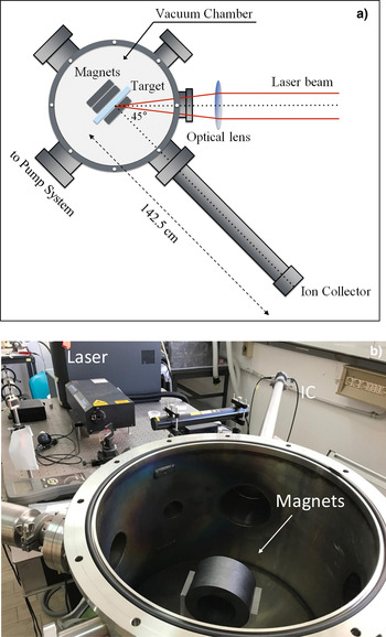
A Nd:Yag laser operating at 1064 nm wavelength, with 3 ns pulse duration, with a spot of 0.5 mm2 surface and intensity of 1010 W/cm2, operating in single pulse or in repetition rate up to 10 Hz, was used for our experiment. The focalization lens is placed externally to the vacuum chamber (10−6 mbar pressure) and the laser goes inside though a quartz window. The incidence angle is 45° and the investigated ion emission occurs along the normal to the target surface as reported in the scheme of Figure 1a and in the photo of Figure 1b.
Scheme of the experimental setup (a) and photographs of the vacuum scattering chamber with the magnets (b).

The irradiated targets were sheets, 2 cm2 surface and 1 mm thickness, of glassy carbon and pure aluminum. The plasma diagnostics was performed with an ion collector (IC) with secondary electron suppression grid, acting such as a Faraday cup, connected in time-of-flight (TOF) approach to a fast storage oscilloscope (Tektronix TDS5104B, 1 GHz, 5 GS/s), placed at a target distance of 142.5 cm. The oscilloscope acquires using as trigger the laser pulse on a time scale of the order of 4 µs/division and a signal yield of the order of 10 mV/division.
The maximum particle energy E Max was calculated using the measured TOF at the faster detected ion signal through the equation:
 $$E_{{\rm Max}} = \displaystyle{1 \over 2}m \cdot \left( {\displaystyle{L \over {{\rm TOF}}}} \right)^2, $$
where m is the ion mass and L the flight distance.
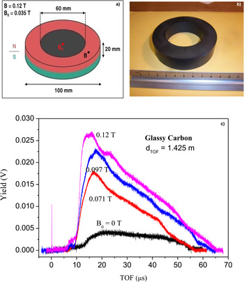
The used permanent magnets were ring shaped constituted by ferrite. A single magnet has an outer diameter of 100 mm and an internal of 60 mm, with a thickness of 20 mm, a scheme, and a photo of one magnet is reported in Figure 2a and 2b, respectively. The produced magnetic field, experimentally measured with a Gaussmeter (Hirst GM08), is axial with a value of 0.12 T on the magnet surface and of 0.035 T at its center. The axis of the magnets is positioned along the normal to the target surface, in correspondence of the laser spot position.
Design of a single ring magnet (a), photographs of a magnet (b), and IC–TOF spectra comparison for glassy carbon plasma emission using different axial magnetic fields (c).

The experiments were conducted as following:
-
1. target without magnets (B = 0 T);
-
2. configuration FB: 1 magnet front-target-magnets back (1, 2, or 4 back). The target is positioned in the rear of the first magnet and followed by other magnets, from 1 up to 4 back magnets (producing a total field from 0.071 up to 0.12 T).
Thus, the maximum number of applied magnets was five, of which one in front of the target (always present) and from one up to four placed axially in the rear side of it. A comparison of the obtained results with and without the magnetic field was performed irradiating in the same experimental conditions.
The experimental results were compared with those obtainable using the simulation code COMSOL (Comsol, 2017), giving the ion and electron trajectories emitted from the target by fixing their angular emission and mean energy and applying the external axial magnetic fields.
The IC plasma diagnostics was employed to characterize the laser-generated plasma in terms of temperature and density. Moreover, indications on the charge state and ion acceleration, in the non-equilibrium plasma, were studied using the Coulomb–Boltzmann-shifted (CBS) velocity distribution f(ν) (Torrisi, Reference Torrisi2016):
 $$f\,(v) = A\left( {\displaystyle{m \over {2{\rm \pi} kT}}} \right)^{3/2} v^3 e^{ - \left[ {(m/2kT)(v - v_k^{} - v{}_{\rm c})^2} \right]}, $$
where A is a constant of normalization, v is the ion velocity, m the ion mass, kT the plasma temperature, v k the adiabatic plasma expansion in vacuum velocity and v c the Coulomb velocity. The total ion velocity along the normal direction to the target surface has three components: the first is the thermal velocity:
 $$v_{\rm T} = \sqrt {\displaystyle{{3kT} \over m}}. $$
The second is the adiabatic plasma expansion velocity:
 $$v_k = \sqrt {\displaystyle{{{\rm \gamma} kT} \over m}}, $$
where γ is the adiabatic coefficient. The third component is the Coulomb velocity:
 $$v_{\rm c} = \sqrt {\displaystyle{{2zeV_0} \over m}}, $$
where z is the ion charge state, e the electron charge, and V 0 the potential applied to the acceleration distance producing the electric field driving the ion acceleration.
The TOF ion spectra deconvolution process can be performed using the CBS approach, permitting to evince the different ion charge states composing the main ion peak and evaluating the plasma temperature and acceleration potential.
NIST data base was used for the calculation of the ionization potentials of the ions of the plasma (Nist, 2017).
2. RESULTS
The first analyzed spectra were acquired irradiating glassy carbon targets in single pulse and detecting the emitted ions as a function of the magnetic field produced by the different magnets placed one in front and, from one up to four, in back to the target. The results of the TOF measurements are reported in the comparison plots of Figure 2c.
Spectra indicate that the maximum yield of carbon ions increases with the applied magnetic field growing from about 4 mV at B = 0 T up to about 27 mV using the configuration FB (1 magnet front-target-4 magnets back). This means that the magnets enhance the axial ion emission toward the IC detector producing a sort of axial ion focalization. The peak shape indicates that all the emitted carbon ion species are enhanced and that a little amount of hydrogen, as contaminant, increases also with the applied magnetic field.
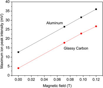
This increment, both in terms of maximum yield intensity (mV) than in terms of total yield (area subtended by the ion peak), is a linear function of the applied magnetic field, as reported in the plot of Figure 3 for C and Al maximum ion yields.
Maximum ion peak intensity versus applied magnetic field.

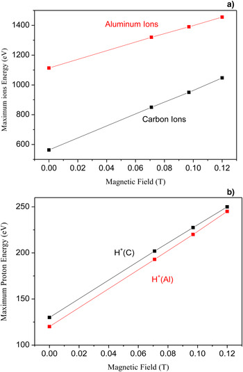
The little proton peak starts at about 9 µs in absence of magnets and at about 6.5 µs in presence of the maximum magnetic field, corresponding to a kinetic energy of about 130 and 250 eV, respectively, indicating that the presence of the magnetic field not only produces yield increment but also energy increment, which in the case of protons is about 92%.
The carbon ion peak starts at about 15 µs in absence of magnets and at about 11 µs in presence of magnets, corresponding to a kinetic energy of about 563 and 1047 eV, respectively, indicating that the presence of the magnetic field not only produces yield increment, but also energy increment, which in the case of carbon ions is about 86%.
The energy released by the plasma to the protons, due mainly to Coulomb interactions in the charge separation zone, represents the conferred energy per charge state of the plasma acceleration. Thus dividing the maximum carbon energy for that of the maximum proton energy we obtain a ratio value of 4, indicating that the faster carbon ions are the C4+. Decreasing the charge state the carbon ion decreases in energy assuming the value of about 140 eV for C1+. This ion energy distribution produces the long tail of the carbon ion peak in the TOF spectrum, which is more elongated due to C x Hy groups produced in the hot plasma, according to literature (Torrisi et al., Reference Torrisi, Gammino, Mezzasalma, Visco, Badziak, Parys, Wolowski, Woryna, Krása, Láska, Pfeifer, Rohlena and Boody2003).
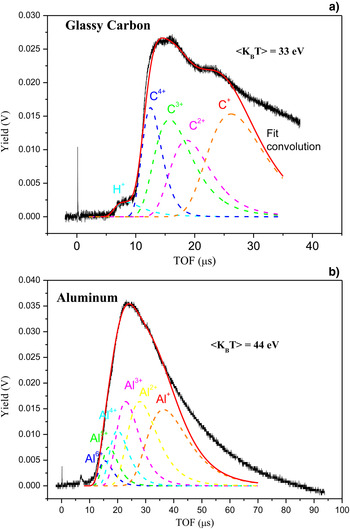
According to the Lotz theory of the ionization cross section, the ion charge state should have a distribution decreasing with the charge state, so the fast C4+ ions present in the plasma will be lower with respect to that of the slower C1+ (Shirkov & Zschornack, Reference Shirkov and Zschornack1996). Moreover, to being the ionization potential of C IV of 64.5 eV, and that of C V of 392 eV, according to NIST ionization potential database (Nist, 2017), this means that plasma should contain electrons with a maximum energy between 65 and 392 eV. Assuming the maximum electron energy to be of about 150 eV and that they have a Boltzmann distribution, the mean energy of the plasma should be about one third of this maximum value, that is, of about 50 eV and the corresponding plasma temperature of about: kT = 2E/3 = 33 eV.
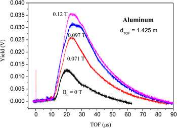
The second analyzed spectra were acquired irradiating aluminum targets in single pulse and detecting the emitted ions in TOF approach as a function of the axial magnetic field produced by the different magnets placed in front and in back (FB) of the target. The results of the TOF measurements are reported in the comparison plots of Figure 4.
IC–TOF spectra comparison for aluminum plasma emission using different axial magnetic fields.

Spectra indicate that the maximum yield of aluminum ions increases with the applied magnetic field growing from about 13 mV, using the configuration B = 0 T, up to about 36 mV for the FB configuration (1 magnet front -target-4 magnets back). This means that magnets focalize, enhancing the axial ion emission directed toward the IC detector. The peak shape indicates that all the emitted aluminum ion species are enhanced and that a little amount of hydrogen, less than for glassy carbon, is present as contaminant.
Similarly to glassy carbon, the aluminum ion yield increases, both as maximum intensity (mV) than as total yield (area subtended by the ion peak). The increment is a linear function of the applied magnetic field, as reported in the plot of Figure 3 for the maximum intensities. This plot demonstrates that the Al ion yield is higher with respect to carbon both in absence of magnetic field than in presence of it. One of the causes of this result is due to the different evaporation temperature, very high in the carbon (4830 °C) with respect to the aluminum one (2450 °C). The lower evaporation temperature of Al reduces its ablation threshold and permits to produce a major Al ablation and vapor pressure than for C.
The aluminum ion peak starts at about 16 µs in absence of magnets and at about 14 µs in presence of the maximum magnetic field, corresponding to a kinetic energy of about 1113 and 1455 eV, respectively, indicating that the presence of the magnetic field not only produces yield increment, but also energy increment, which in the case of aluminum ions is about 30%, thus resulting more contained with respect to the glassy carbon case. Although for Al the proton emission is less evident with respect to C a little proton signal is visible in the spectra occurring at about 9.5 and 6.5 µs without and with the maximum applied magnetic field, respectively. Such TOFs correspond to the energy of 120 and 250 eV for the case without and with the magnetic fields, respectively, indicating proton acceleration similar to the case of the glassy carbon target. Dividing the maximum aluminum energy by the proton energy it is deduced a maximum Al charge state of about 6+. This means that the maximum electron energy should be within the ionization potential of Al V and Al VI, which is 154 and 190 eV, respectively (Nist, 2017). Thus in this case, it is possible to assume that the maximum electron energy is little higher than for carbon plasma, in fact it is of about 200 eV, corresponding to a mean Boltzmann energy of about 66.7 eV and that the plasma temperature is of the order of kT = 2E/3 = 44 eV.
The kinetic energy enhancement versus the applied axial magnetic field intensity is reported in Figure 5a for Al and C ions, while in Figure 5b for protons coming from the Al and C plasmas. The enhancement is linear with the applied value of the axial magnetic field.
Maximum ion energy (a) and maximum proton energy (b) for carbon and aluminum plasmas versus applied axial magnetic field.

A confirm of the given temperatures and of the supposed number of charge states in C and Al laser-generated plasma comes from the deconvolution of the IC spectra using the CBS function given in Eq. (2). Figure. 6 shows two typical examples of IC spectra deconvolution relative to the carbon plasma (a) and to the aluminum plasma (b) obtained with the maximum axial magnetic field application of 0.12 T. The spectrum relative to carbon plasma shows the deconvolution of hydrogen and of four charge states of carbon ions with a width of the Boltzmann distributions corresponding to a mean temperature of 33 eV.
IC–TOF spectra deconvolution using the CBS function for ion emission from glassy carbon (a) and aluminum (b) plasmas.

The spectrum relative to aluminum plasma shows the deconvolution of six charge states of aluminum ions with a width of the Boltzmann distributions corresponding to a mean temperature of 44 eV.
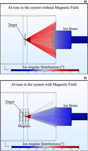
The COMSOL code (Comsol, 2017) permitted to simulate the ion focalization due to the presence of the magnets, as reported in Figure 7 for the case of Al ions emitted with the angular distribution given by literature, without magnetic field application (a) and with the 0.071 T magnet application (b). Simulations are agreed with the experimental enhancement of ion yield measured for Al and for C plasmas, due to a magnetic focalization toward the IC detector. Such focalization enhances the ion current of about a factor 6.6 for the C ions and of about 2.8 for Al ions for a maximum magnetic field application of 0.12 T. This result, obtained both experimentally and by simulation code, indicates that the magnetic focusing decreases with the atomic mass of the deflected ions and that a higher magnetic field should be applied to focalize heavy ions toward the IC placed axially at 1.425 m from the target.
COMSOL simulation of the Al ion emission from the laser-irradiated target without (a) and with the 0.071 T applied axial magnetic field (b).

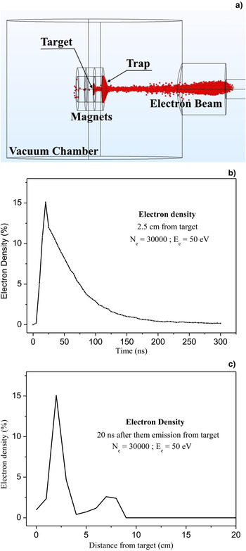
The result of the ion energy increasing by applying the magnetic field can be explained by the electron traps generation due to the magnetic fields in front of the target that drives the plasma ion acceleration, as already presented in our previous work (Torrisi et al., Reference Torrisi, Margarone, Gammino and Andò2007). The magnets, in fact, modify the trajectories of the electrons emitted from the plasma producing some zones of electrons accumulation at high density near to the target surface that influences the spatial Coulomb forces interacting with the emitted ions. Such density, of course, is a function of the time and of the space and reaches the maximum value at a time, from the laser pulse, depending mainly on the electron yield emission, energy distribution and applied axial magnetic field. The COMSOL simulation program permits to generate the trajectories of the electrons emitted from the plasma without and with the magnetic field application. Figure 8 shows an example of electron trajectories simulation emitted from the Al plasma (a) and of their density as a function of the time from the laser shot (b) and of the localization space from the target surface (c).
COMSOL simulation of the Al electron emission from the used 0.097 T axial magnetic field (a), electron density versus time from the laser shot at 2.5 cm distance from the target (b), and electron density at 20 ns from the laser shot versus distance from the target surface (c).

The simulation is obtained for 30.000 electrons (N e) with an average energy (E e) of 50 eV and a magnetic field of 0.097 T. It is possible to observe that the maximum density occurs at about 25 ns from the laser pulse and that the trap is localized at about 2.5 cm distances from the target surface, that is, at the end of the magnetic ring placed in front of the target. The electron density is maintained high for times of about 100 ns from the laser shot, permitting to accelerate also slow ions emitted from the plasma. At 20 ns from the laser shot its maximum value is maintained high at about 4 cm from the target and decreases strongly at larger distances.
Of course by changing the electron energy the maximum density will change intensity, position and occurring time, for example, decreasing the mean electron energy to 10 eV the simulations indicate that the trap will increase in intensity and will be localized at about 2.5 cm after a time of 50 ns from the laser shot.
4. DISCUSSION AND CONCLUSIONS
The subject presented in this paper is of special interest not only for the Physics of base discussed around the laser–matter interaction and plasma production, but overall for the many useful applications that can be improved applying suitable magnetic fields to enhance the flux and the energy of the emitted ions. For example, LIS can inject more ions toward the accelerator system (Gammino et al., Reference Gammino, Torrisi, Ciavola, Andò, Wolowski, Laska, Krasa and Picciotto2003), PLD of may enhance the film thickness growth rate (Torrisi et al., Reference Torrisi, Trusso, Di Marco and Parisi2001), nuclear reactions occurring in laser-generated plasma may enhance their yield (Torrisi et al., Reference Torrisi, Cavallaro, Cutroneo, Giuffrida, Krasa, Margarone, Velyhan, Kravarik, Ullschmied, Wolowski, Szydlowski and Rosinski2013), target-normal-sheath-acceleration regime may focalize accelerated ions (Borghesi, Reference Borghesi2014), and the use of multiple ion implantation technique can improve the implanted doses (Cutroneo et al., Reference Cutroneo, Torrisi, Ullschmied and Dudzak2016).
Of course the enhancements will depend strongly on the applied magnetic fields in intensity and in geometry.
The performed work is not intended to be exhaustive or conclusive, on the contrary it is intended to be preliminary and adapts to stimulate further studies to optimize the axial and transversal magnetic fields that may be applied to ions emitted from a source to increase the emittance, change the ion and electron angular spreads, and modify the particle energy, thank to spatial and temporal localized electron traps.
Our experiment was only demonstrative and limitative because only two kind of light ions, carbon, and aluminum, were used. It should be extended to heavy ions, to higher magnetic fields with different spatial distributions and to higher laser intensities, such as we are operating with a work in progress.
Moreover, in our experiments further studies are need to tray different magnetic fields, applied both axially and transversally, to study the angular distribution modifications of the ions by applying the magnetic fields as a function of their energy, to simulate the ion trajectories, to calculate the real flight distances under magnetic field to arrive to the final detector and to study the effects using repetitive laser pulses generating near continuum ion currents. The ion focalization here presented increases up to 6.6 times the ion current, but, of course, it is possible to optimize more the focalization to reach higher values. Analogously the electron traps can be created more near to the target surface to enhance the plasma electric field driving the ion acceleration. Moreover, the applied magnetic field must be also optimized to be adapted to higher laser intensities and to different ion species emitted from laser-generated plasmas, so that similar results can be obtained with laser intensities above 1014 W/cm2 at which more energetic acceleration occurs.