I. INTRODUCTION
The development of wireless antenna has grown rapidly over the past three decades. As a result, there is huge demand of small-size antenna with wide bandwidth and high radiation efficiency; which has created enormous challenge for antenna researchers. Dielectric resonator antenna (DRA) attract researchers due to its wide bandwidth and high radiation efficiency even operated at high frequency (millimeter wave band) as compared with microstrip antenna, due to the absence of surface wave and also it radiates through the entire surface [Reference Petosa1–Reference Long, Stuart, Mark and Shen4]. The cylindrical shape dielectric resonator (DR) was the first basic geometry, which was used as antenna element for radiation and named as cylindrical dielectric resonator antenna (CDRA) [Reference Kajfez and Guillon3, Reference Long, Stuart, Mark and Shen4]. The cylindrical dielectric resonators have available with following lowest order modes such as TE01δ , TM01δ , HE11δ , EH11δ , TE011+δ , etc. [Reference Long, Stuart, Mark and Shen4]. For each mode, it has its own radiation pattern which can be castoff as per required application.
Multi-element and multi segmentation concept has been reported in literature as a basic technique to improve the impedance bandwidth [Reference Petosa, Simons, Siushansian, Ittipiboon and Cuhaci5–Reference Gebril, Rahim and Abdulrahman10]. The bandwidth can also be improved by the introduction of an air gap between the DR element and the ground plane [Reference Kishk, Glisson, Junker and Kajfez6, Reference Shum and Luk7]. Stacking of the cylindrical DR elements, excited with HE11δ mode was investigated, and found 25% impedance bandwidth for wideband application [Reference Kishk, Ahn and Kajfez8, Reference Kishk, Zhang, Glisson and Kajfez9]. In the sequence of multi-element, some researcher has made splitting and sectoring of the basic elementary shape of DRA. Through the sectoring and splitting, researcher are able to reduce the radiation area as well as volume, which is useful for designing a low weight antenna with wide bandwidth [Reference Matthew, Tam and Ross11–Reference Cormos, Laisne, Gillard, Bolzer and Nicolas19]. By using metalized faces for the sectored DRA, volume of the antenna can be reduced [Reference Matthew, Tam and Ross11, Reference Matthew, Tam and Ross12]. The sectored hemispherical DRA has been investigated by Guha et. al. for wide bandwidth and monopole-like radiation pattern. Through half-split hemispherical DRA and segmented quarter split hemispherical DRAs, 35% of impedance bandwidth has been achieved as broadband variant low-profile DRA [Reference Guha, Gupta, Kumar and Antar13, Reference Guha and Antar14]. Compact cylindrical sector DRA has been introduced with a 75% reduction in volume compared with conventional CDRA with the support of fractional modes and allowance of dual frequency with dual-feed operation [Reference Mongia, Ittipiboon and Antar15]. A slot-coupled half-split CDRA placed on a metallic plane excited with magnetic dipole mode provides 10% enhancement in bandwidth with monopole-like radiation pattern [Reference Mongia16]. The DR elements have been excited with HEM11δ and HEM12δ modes for wideband performance with bandwidth enhancement due to split in dielectric cylinder [Reference Kishk and Glisson17]. A microstrip-coupled rectangular DRA has been investigated by using metallization, which is responsible for improvement in bandwidth with size reduction [Reference Saed and Yadla18, Reference Cormos, Laisne, Gillard, Bolzer and Nicolas19].
Monopole-like radiation pattern has been reported by some researcher through splitting the basic shapes [Reference Matthew, Tam and Ross11–Reference Cormos, Laisne, Gillard, Bolzer and Nicolas19] as well as different DRA shapes with multi-element concept [Reference Mongia, Ittipiboon, Bhartia and Cuhaci20–Reference Gangwar, Singh and Kumar23]. The dielectric ring resonator antenna has been introduced for small and compact electric monopole-like radiation by Mongia et al. [Reference Mongia, Ittipiboon, Bhartia and Cuhaci20]. On the basis of multi-element trend, four-element CDRA has been introduced by Guha and Antar [Reference Guha and Antar21], which shows monopole-like radiation pattern with 29% impedance bandwidth. Four-element rectangular and triangular DRAs excited with coaxial probe feeds provides about 35% bandwidth with monopole-like radiation pattern [Reference Gangwar, Ranjan and Aigal22, Reference Gangwar, Singh and Kumar23].
This paper presents the design and development of composite forms of multi-element dual-segment quarter cylindrical dielectric resonator antennas (q-CDRAs). The performance of four-element dual-segment q-CDRA (DS q-CDRA) has been compared with single- and two-element dual-segment composite form of q-CDRAs. The simulation studies of the proposed antennas are carried out using Ansoft HFSS simulation software and the results are experimentally verified. The proposed four-element dual-segment composite q-CDRA shows improvement in bandwidth as compared with single- and two-element dual-segment composite q-CDRA. The performance of the proposed four-element dual segments composite q-CDRA has also been compared with previous published structure. The prototype of multi-element DS q-CDRAs have been fabricated and tested. Measured results have been compared with simulated one and found good agreement between each other. Proposed four-element dual segments composite q-CDRA provides 85.13% bandwidth (|S 11| ≤ −10 dB) with a uniform monopole-like radiation pattern over the entire band.
II. ANTENNA GEOMETRY
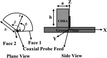
The q-CDRA has been made through cutting a one-forth part of the CDRA. The CDRA has been shown in Fig. 1, which cuts a sector with an arbitrary angle β on a ground plane. For q-CDRA the angle β is 90°, i.e. angle between faces 1 and 2. Its sectored face left open, so that approximately magnetic wall boundary conditions exist on it.
Geometry of cylindrical sector CDRA.

By assuming a magnetic wall approximation for complete sectored surface, as it is open in air. The field exits inside the cylindrical sector DRA in terms of TM mnp modes are [Reference Luk and Leung2, Reference Kajfez and Guillon3]
 $$\eqalign{E_z^{mnp} & = [AJ_m(k_rr) + BY_m(k_rr)].[C{\rm sin}(v\phi ) \cr & \quad + D{\rm cos}(v\phi )]{\rm cos}(k_zz).} $$
Here A, B, C, and D are arbitrary constant, which depends on placement and feed of the DRA. J m and Y m denote first and second kind mth-order Bessel function, respectively. Where m is positive real number, which depends upon boundary conditions; n and p are positive integers. For simplification of excitation, coaxial probe feed has been used at the center of cylinder.
A) DS q-CDRA
The dual-segmentation approach has been applied for enhancing the bandwidth of antenna. The lower segment should have low dielectric constant material [Reference Petosa, Simons, Siushansian, Ittipiboon and Cuhaci5]. The DS q-CDRA has been proposed through keeping two similar sector of q-CDRA in stacked form. The resonant frequency calculation has been depended upon the dominant mode excitation.
The resonant frequency of the TM mnp mode:
 $$k_r^2 + k_z^2 = k^2 = {\varepsilon} _{r,eff}\left( {\displaystyle{{2\pi f} \over c}} \right)^2,$$
where
 $k_r = {X}^{\prime}_{mn}/a\quad {\rm and}\quad k_z = (2p + 1)/2h_{eff}$
are wave numbers.
 ${X}^{\prime}_{mn}$
is root satisfying
 ${J}^{\prime}_m({X}^{\prime}_{mn}) = 0.$
So, the final equation for the resonant frequency of dual-segment composite form q-CDRA for the TM mnp mode is [Reference Kajfez and Guillon3]
 $$f_{mnp} = \displaystyle{c \over {2\pi a\sqrt {\mu _{r,eff}{\varepsilon} _{r,eff}}}} \sqrt {{{X}^{\prime}}_{mn}^2 + {\left[ {\displaystyle{{\pi a} \over {2h_{eff}}}(2p + 1)} \right]}^2}. $$
For β = 90° both faces of the cylindrical sector has been left open, so it will form approximate magnetic walls condition. The magnetic walls on faces 1 and 2 have the boundary conditions
 $$\displaystyle{{\partial E_z} \over {\partial \phi}} = 0\;{\rm at}\;\phi = 0\;{\rm and}\;\phi = \beta, \;n = \displaystyle{{v\pi} \over \beta}, \;\;{\rm where}\;0 \lt \beta \lt 2\pi, $$
 $$\varepsilon _{r,eff} = \displaystyle{{h_{upper} + h_{lower}} \over {h_{upper}/\varepsilon _{r,upper} + h_{lower}/\varepsilon _{r,lower}}},$$
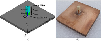
where v is a non-zero positive integer to satisfy the boundary conditions at sectored faces 1 and 2, respectively. The solution for both faces are open required C = 0. The resonant frequency depends on radius, effective height (h upper + h lower ), and effective dielectric constant (ε r,eff ) of the cylindrical sector DRA for a particular mode. The effective dielectric constant of the DR element has been calculated through equation (5). The resonant frequency for TM01δ mode of the DS q-CDRA has been calculated using equation (3) for 0 < δ < 1, which will lie between 6.5 and 10.5 GHz, depends on δ value [Reference Kajfez and Guillon3]. Proposed DS q-CDRA has been designed, fabricated, and shown in Fig. 2.
(a) Geometry and (b) fabricated structure of dual-segment q-CDRA.

The dimension of proposed DS q-CDRA structure has radius a = 4 mm and the effective height h eff = 13 mm. The upper segment (h upper ) and the lower segment (h lower ) height have been kept 9 and 4 mm, respectively. The dielectric constant of the upper and lower segments has been chosen as ε r,upper = 9.8 (Alumina ceramic, Ants Ceramics Private Ltd.) and ε r,lower = 2.1 (Teflon), respectively. The DR element has been exited through coaxial probe feed at the center of the ground plane of dimension 50 × 50 × 3 mm. The ground plane has been chosen as copper plate (99% copper). As the dimension of DR element is very less compare with the ground plane, so it can be assumed that the ground plane behaves like an infinite ground plane for the DRA. The probe height has been optimized and found 9.2 mm though extensive simulations for minimum return loss.
B) Two elements DS q-CDRA in composite form
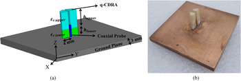
Two elements DS q-CDRA in composite form has been designed, fabricated and shown in Fig. 3. Composite form of two elements DS q-CDRA has been introduced by combining two similar quarter split sector of the dual-segment CDRA. Each elements of the proposed DRA has same dimensions and material properties as of DS q-CDRA discussed in Section 2.1. The centrally coaxial probe-fed DR elements are packed together in a compact way on a metallic ground plane (99% copper) of size 50 × 50 × 3 mm3. The probe height has been optimized though extensive simulations for minimum return loss and the height of the probe is found to be 9 mm from the bottom of the ground plane.
(a) Geometry and (b) fabricated structure of two-element dual-segment composite q-CDRA.

C) Four elements dual-segment composite q-CDRA
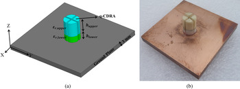
Proposed four elements dual-segment composite q-CDRA has been designed and fabricated prototype shown in Fig. 4. Four uniform quarter split sector of the DS q-CDRA has been kept on a compact way, such that it form complete cylinder with an equal air gap as shown in Fig. 4(a). The antenna geometry and fabricated structure of the proposed dual-segment four-element composite form of q-CDRA is shown in Figs 4(a) and 4(b), respectively. Each elements of the proposed DRA has same dimensions and material properties as of DS q-CDRA discussed in Section 2.1. The centrally fed coaxial probe has been used for excitation of the proposed DRA. The DR elements are packed together in a compact way on a metallic ground plane (99% copper) of dimensions 50 × 50 × 3 mm3. The SMA probe has been fitted at the center of the ground plane. As the dimension of DR element is very less compare with the ground plane, so it can be assumed that the ground plane behaves like the infinite ground plane for the DRA. The DRA has been fixed on the ground plane using adhesive material (fewiquick). The probe height has been optimized though extensive simulations and found 9 mm from the bottom of the ground plane for minimum return loss. The diameter of the probe has not much effect on coupling of DRA.
(a) Geometry and (b) fabricated structure of four-element dual-segment composite q-CDRA.

III. RESULTS AND DISCUSSION
The input characteristic of the proposed DS q-CDRAs in composite forms have been investigated using Ansoft HFSS simulation software and compared with the measured result. The input characteristics measurement has been performed using Rohde & Schwarz Vector Network Analyzer (Model No. ZVM, 10 MHz–20 GHz). For simulation of the proposed antenna, Ansoft HFSS simulation software has been used. For the excitation, wave port mode of excitation has been chosen at the surface of coaxial probe feed. The radiation boundary has been fixed at the distance of ten times of λ/4. The solution frequency has been provided same as the resonant frequency. Fast sweep mode has been chosen for the generation of result and the maximum value of 0.02 has been chosen for terminating for the adaptive solution, which gives approximate accurate simulation results. Total no. of samples has been taken 400 for entire bandwidth for Ansoft HFSS as well as VNA.
A) DS q-CDRA
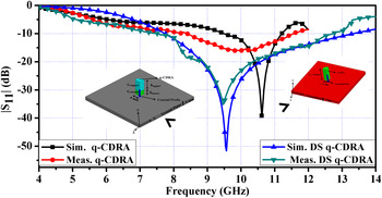
The |S 11| versus frequency curves of the proposed DS q-CDRA has been compared with q-CDRA, which is shown in Fig. 5. The DS q-CDRA has wide bandwidth compare with q-CDRA, which may be due to decrease in effective dielectric constant. As, both the prototype has been designed for same dimension of effective height 13 mm and radius 4 mm. The simulated as well as measured operating bandwidth, resonant frequency and percentage bandwidth has been extracted from Fig. 5 and shown in Table 1. The measured resonant frequency for DS q-CDRA is found to be 9.45 GHz, which is impending in between theoretically calculated resonant frequency range (7.2–10.93 GHz) using equation (3). The value of simulated and measured resonant frequency is found 9.5 and 9.45 GHz, respectively. From Fig. 5 and Table 1, it can be observed that there is slightly mismatch found between the simulated and measured data, which may be due to the fabrication error.
|S 11| versus frequency curves of q-CDRA and dual-segment (DS) q-CDRA.

Resonant frequency and Return loss performance of proposed composite dual segment q-CDRAs.

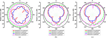
The near-field distributions revels TM01δ -like mode as dominant mode at resonant frequency of the dual segment q-CDRA. The far field patterns of the DS q-CDRA have been studied at resonant frequency. Simulated and measured radiation pattern of the DS q-CDRA has been shown in Fig. 6. The radiation pattern measurement has been performed inside anechoic chamber. Measured radiation pattern shows close agreement with simulated one. At ϕ = 90° (YZ-plane) the broadside radiation with asymmetric in nature has been found and at ϕ = 0° (ZX-plane) the broadside with tilt toward 45° and −45° with null at θ = 0°.
Radiation pattern of DS q-CDRA (a) in XY plane (b) in YZ plane (c) in ZX plane at resonant frequency 9.45 GHz.

B) Two elements DS q-CDRA in composite form
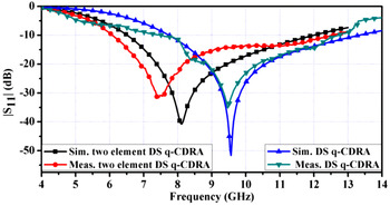
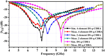
The |S 11| versus frequency curves of the single- and two-element dual-segment composite q-CDRA has been shown in Fig. 7. The operational bandwidth, resonant frequency, and percentage bandwidth has been extracted from Fig. 7 and tabulated in Table 1. Two elements dual-segment composite q-CDRA provides wide bandwidth as compare with single-element DS q-CDRA due to more radiation area. For two elements dual -egment composite q-CDRA measured resonant frequency is found to be 7.75 GHz for TM01δ -like mode as dominant mode, which is very close to simulated resonant frequency of 8.05 GHz. From Fig. 7 and Table 1, it can be observed that there is slightly mismatch between the simulated and measured data, which may be due to the fabrication error. For fixing two ceramics material, adhesive material (feviquick) has been used, which may be responsible for shift in measured resonant frequency [Reference Aras, Shahrieel, Abidin, Aziz and Zulhani24, Reference Aras, Shahrieel, Aziz and Abidin25].
Comparison of |S 11| versus frequency curves of the proposed single-element and two-element dual-segment (DS) composite q-CDRA.

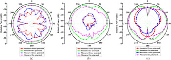
The distribution of E- and H-fields of two elements dual-segment composite form of q-CDRA reveals the TM01δ -like mode as a dominant mode at resonant frequency. The far-field patterns of the two elements dual-segment composite q-CDRA at resonant frequency are studied through simulation and shown in Fig. 8. The far-field measurement of the fabricated antenna has been performed inside the anechoic chamber. Measured radiation pattern has close agreement with simulated one. It can be observed from Fig. 8, that the radiation pattern in E-plane (ϕ = 90 and ϕ = 0°) having larger radiation along lower elevation angle and azimuthally symmetrical pattern.
Radiation pattern of two elements dual-segment composite q-CDRA: (a) in the XY plane, (b) in the YZ plane, and (c) in the ZX plane at resonant frequency 7.75 GHz.

C) Four elements DS q-CDRA in composite form
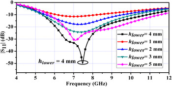
The proposed four element DS q-CDRA has been designed for desired operating frequency band. The effective height (h effective = h upper + h lower ) has been kept constant as 13 mm. The size of each segment has been decided using parametric analysis as shown in Fig 9. From Fig. 9, it can be observed that at h lower = 4 mm, proposed antenna is showing wide bandwidth and minimum return loss.
Variation in |S 11| curve with frequency for different heights of lower segment of four elements dual-segment composite q-CDRA.

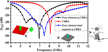
The dual segmentation approach has been applied for bandwidth enhancement. The lower segment should have low dielectric constant material [Reference Petosa, Simons, Siushansian, Ittipiboon and Cuhaci5]. The low dielectric constant materials are responsible for decreasing the effective dielectric constant of the material, which results enhancement in bandwidth. Figure 10 shows variation in the |S 11| curve with frequency for four-element q-CDRA, CDRA and four elements dual-segment composite q-CDRA. From Fig. 10, it can be depicted that four-element DS q-CDRA has wide bandwidth compare with four-element q-CDRA and CDRA for same height of DR element, i.e. 13 mm.
Variation in |S 11| curve with frequency for four-element q-CDRA, CDRA, and four elements dual-segment composite q-CDRA.

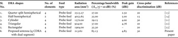
The |S 11| versus frequency curves of the proposed prototypes in comparative form has been shown in Fig. 11. From Fig. 11, the resonant frequency, operating frequency range and the percentage bandwidth of the proposed structures are extracted and shown in Table 1. From Fig. 11 and Table 1, it can be observed that proposed four elements dual-segment composite q-CDRA provides wide bandwidth (~85.13%) and covers complete 5.0 GHz wireless local area network (WLAN) and worldwide interoperability for microwave access (WiMAX) band. There are slightly mismatch found between the simulated and measured resonant frequency, which may be due to the fabrication error. From Fig. 11, it can also be observed that the proposed four elements dual-segment composite q-CDRA having lower resonant frequency as compared with single- and two elements dual-segment composite q-CDRA. This is due to increase in the volume and surface area of the proposed structure as compared with other composite forms of q-CDRAs such as single element and two elements. Table 2 shows performance comparison of proposed antenna with different published composite DRAs. From Table 2, it can be observed that the proposed four-element dual-segment composite q-CDRA has better performance compare with other published DRAs. It can be also observed from Table 2, that the proposed four-element dual-segment composite q-CDRA is taking very less radiation area for same performance or even better than other shapes.
Comparison of |S 11| versus frequency curves of four-element with single element and two elements dual-segment (DS) composite q-CDRA.

Comparison of the proposed four-element dual-segment composite q-CDRA performance with similar type of antenna.

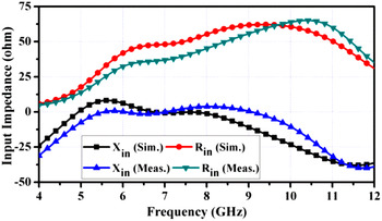
The input impedance versus frequency characteristic of the proposed four-element dual-segment composite q-CDRA has been investigated using Ansoft HFSS simulation software at resonant frequency 7.45 GHz. Simulated input impedance has been compared with measured ones and shown in Fig. 12. From Fig. 12, the measured and simulated values of input resistance at the resonant frequency of the proposed composite q-CDRA have found 47.2 and 50.3 Ω, respectively. The measured value of input resistance of the proposed composite q-CDRA is in close agreement with the simulated one, which shows good impedance match with 50 Ω coaxial probe feed.
Variation of input impedance versus frequency curve of the proposed four-element composite q-CDRA.

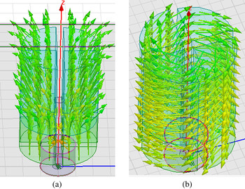
The near-field distributions of the proposed four-element dual-segment composite q-CDRA have been performed at resonant frequency through Ansoft HFSS simulation software. The distribution of E- and H-fields of the proposed composite q-CDRA are shown in Figs 13(a) and 13(b), respectively. It is apparent from Fig. 13 that the distribution of fields in the DR elements of the proposed four-element dual-segment composite q-CDRA is TM01δ -like mode as dominant mode at resonant frequency. The resonant frequency of the proposed antenna is 7.5 GHz that exactly corroborates the dominant mode resonance in proposed antenna. It can also be observed that the electric field component face their counter vectors in the XY plane and thus causes no radiation along the broadside direction. The resulting electric fields are linearly polarized along the z-axis and thus lead to a vertically polarized radiation surrounding the radiating structure like a quarter wave magnetic monopole [Reference Petosa1].
(a) E-field and (b) H-field distributions in the proposed four-element dual-segment composite q-CDRA.

The far-field patterns of the proposed four-element dual-segment composite q-CDRA at resonant frequency are studied through simulation and measurement. The simulation has been performed using Ansoft HFSS simulation software. The measurement of the fabricated antenna has been performed inside the anechoic chamber. The simulated and measured radiation patterns of the proposed composite q-CDRA at the resonant frequency 7.45 GHz are shown in Figs 14(a)–14(c) in the XY (θ = 90°), YZ (ϕ = 90°), and ZX (ϕ = 0°) planes, respectively. The simulated and measured radiation patterns have also been observed at lower (6.0 GHz) and upper frequency (9.5 GHz) of resonant frequency (7.45 GHz) in all three planes are shown in Figs 15 and 16, respectively. From Figs 14–16, it can be observed that the simulated radiation pattern of the proposed four elements dual-segment composite q-CDRA are in good agreement with measured one. It can also be observed that, the radiation pattern of the proposed composite q-CDRA has omnidirectional pattern in the XY plane. This is may be due to the fact that the proposed composite q-CDRA has no radiation along broadside of the antenna. It is confirm with the counteracting E-field distributions within the elements of the proposed composite q-CDRA [Reference Kajfez and Guillon3]. The proposed four-element dual segments composite q-CDRA has shown monopole-like radiation pattern in the YZ and ZX-planes at all the three frequencies. The cross-polarization level is found to be 20 dB down w.r.t to the polarization level of the proposed q-CDRA for all the three planes at different measured frequencies. For the E-plane due to TM01δ -like mode it create null at θ = 0°. At ϕ = 0° (ZX-plane) and ϕ = 90° (YZ-plane) shows the azimuthally symmetric radiation pattern for the E-plane (ZX and YZ) and radiates strongly along low elevation angles. So it can be used as an electric monopole radiator.
Radiation pattern of the proposed four-element dual-segment composite q-CDRA: (a) in the XY plane, (b) in the YZ plane, and (c) in the ZX plane at resonant frequency 7.4 GHz.

Radiation pattern of the proposed four-element dual-segment composite q-CDRA: (a) in the XY plane, (b) in the YZ plane, and (c) in the ZX plane at frequency 6 GHz.

Radiation pattern of the proposed four-element dual-segment composite q-CDRA: (a) in the XY plane, (b) in the YZ plane, and (c) in the ZX plane at frequency 9.5 GHz.

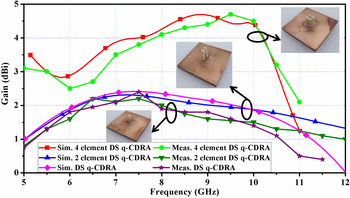
The simulated and measured peak gain versus frequency curves of the proposed DS q-CDRA has been shown in Fig. 17. The gain has been measured at elevation and azimuth of 45°. Three antennas method has been used for gain measurement [Reference Balanis26]. For gain measurement, two similar types of standard horn antennas have been used and the gain of both horn antennas should be known at the measured frequency. The third antenna will be the proposed antenna for which the gain has to be calculated. From Fig. 17, it can be observed that the gain of the proposed antenna is almost constant in a desired bandwidth with the highest value of 4.85 dBi for four-element dual-segment q-CDRA. Form Fig. 17, it can be observed that the DS q-CDRA and two -lement DS q-CDRA has the highest gain of 2.5 dBi, which is less compare with four-element DS q-CDRA. This is may be due to the decrease in an effective radiation area. It can also be observed from Fig. 17 that there is a close agreement with the measured and simulated gain of the proposed antennas. The value of simulated radiation efficiency and peak directivity at the resonant frequency of the proposed four-element DS q-CDRA is found 98.50% and 5.65 dB, respectively.
Variation of gain versus frequency curve for dual-segment (DS), two-element dual-segment and four elements dual-segment composite q-CDRA.

IV. CONCLUSION
A probe-fed multi-element and multi-segment q-CDRA in composite forms have been designed and fabricated. The proposed four-element dual-segment composite q-CDRA shows better option for monopole wideband antenna. The proposed antennas have much more compact compare with other conventional monopole antennas. Proposed antennas have been designed with splitting the basic structure and using the segmentation technique for bandwidth enhancement. The antenna characteristics of the proposed prototypes have been compared with each other. The four-element dual-segment composite q-CDRA provides wider bandwidth (~85.13%) compare with other proposed antenna. It has been also observed that the proposed four-element dual-segment antenna has better performance than the other similar type of previous published designed antenna. The proposed four-element dual-segment composite q-CDRA has found a suitable application in C-band and X-band with complete covering of the 5.0 GHZ WLAN and WiMAX band.
ACKNOWLEDGEMENTS
R. K. G. wishes to acknowledge Directorate of Extramural Research & Intellectual Property Rights (ER&IPR), DRDO, India for financial support of this work through Extramural Research Grant Project No. ERIP/ER/1303145/M/01/1549. The authors also would like to thank Professor Dharmendra Singh, Department of Electronics and Communication Engineering, IIT Roorkee, India, for his guidance and also for providing his antenna measurement facility at IIT Roorkee.
 Pinku Ranjan born in Nalanda (Bihar), India, in 1988. He received his B. Tech. degree in Electronics and Communication Engineering from Jawaharlal Nehru Technological University (JNTU) Hyderabad, India, in 2010. He is currently pursuing his Ph.D. as a Senior Research Fellow in the Department of Electronics Engineering from Indian School of Mines, Dhanbad, India. He served as Junior Research Fellow in the Department of Electronics Engineering, Indian School of Mines, Dhanbad, India, during 2012–2014. He has authored or co-authored for more than eight research paper in international/national journal/conference proceedings. His research interests include Dielectric Resonator Antenna and Bio-Electromagnetics. He is a student member of IEEE Society.
 Ravi Kumar Gangwar was born in Bareilly (Uttar Pradesh), India, in1983. He received the B. Tech. degree in Electronics and Communication Engineering from U.P. Technical University, Lucknow, India, in 2006; and Ph.D. degree in Electronics Engineering in 2011 from the Indian Institute of Technology (Banaras Hindu University), Varanasi, India. He is currently an Assistant Professor in the Department of Electronics Engineering, Indian School of Mines, Dhanbad. He served as a Senior Research Fellow/Junior Research Fellow in the Department of Electronics Engineering, IIT-BHU during 2007–2011. He has authored or coauthored over 72 research papers in international/national journals/conference proceedings. His research interest includes dielectric resonator antenna, metamaterial and bio-electromagnetics. He is member of IEEE APS Society. He is a reviewer of PIER, International Journal of Electronics, International Journal of Microwave and Wireless Technology, Wireless Personnel Communication international journals. Indian Journal of Radio & Space Physics (IJRSP), Indian Journal of Pure & Applied Physics (IJPAP) journals.