
I. INTRODUCTION
When metals or alloys are subjected to an aggressive oxidizing environment at high temperature, the residual stress is inevitably generated. Reference Stephen1–Reference Clarke3 Furthermore, the stress distribution can influence the oxidation kinetics (i.e., growth of the scale). It is greatly important to determine the stress field together with the growth of the oxide film, and this is because the lifetime of high-temperature metals or alloys is controlled by the stress and the oxidation resistance. Generally speaking, the oxidation resistance depends on the mechanical properties of the forming oxidation scale whether it can prevent the underlying metal substrate from further oxidation. Evans Reference Evans4 pointed out that Alumima was often regarded as a barrier for oxygen diffusion because its oxide Al2O3 had excellent properties at high temperature, superior adherence, and slow growth rate compared with other oxides. Reference Reddy, Hovis, Heuer, Paulikas and Veal5,Reference Hu, Hovis and Heuer6 The mechanism of the stress generation is not completely clear. Therefore, the stress analysis during oxidation has attracted more and more attention.
At present, the main possible origins of the stress generation include: (i) epitaxy relationships between metal substrate and oxide scale (lack of compatibility of the crystalline lattices). Reference Freund and Nix7,Reference Zhang, Lee, Guido and Hsueh8 The epitaxy is an interface phenomenon and the growth of a thin layer on a substrate generally coincides with an incompatibility of the two crystalline lattices (i.e., lattice mismatch). Generally, the lattice parameter of an oxide is significantly larger than that of the metal. This large lattice mismatch Reference Panicaud, Grosseau-Poussard and Dinhut9–Reference Clarke11 makes the formation of coherent metal–oxide interface energetically unfavorable. Thus a mismatch strain necessarily accommodates the difference in the lattice parameters at the interface and decreases away from the boundary where the lattice is relaxed. This phenomenon induces stresses at a microscopic level. (ii) Mismatch in the coefficients of thermal expansion and molar volume between the film and the substrate. Reference Evans and Hutchinson12–Reference Hu14 (iii) Phase transformation, Reference Volkert15,Reference Grosseau-Poussard, Panicaud and Ben Afia16 densification, spallation, failure, Reference Evans4,Reference Bull17 and even crack. Reference Wang, Wu, Wang and Chen18 These show that the oxidation can lead to the generation of the stresses. (iv) The possibility that the oxide grows in the oxide grain boundaries. (v) The oxygen dissolution in the metal or alloy. Reference Grosseau-Poussard, Panicaud and Ben Afia16
Taking aim at these origins, various models have been developed to describe the stress evolution during oxidation. Evans Reference Evans4 and Limarga et al. Reference Limarga and Wilkinson19,Reference Limarga and Wilkinson20 developed stress and diffusion behavior model. Zhou et al., Reference Zhou, Qu and Cherkaoui21 Wang et al., Reference Wang, Suo and Shen22 and Suo et al. Reference Suo and Shen23 took into account the interplays among the chemical reaction, diffusion and stress and developed the corresponding coupled models. Panicaud et al. Reference Panicaud, Grosseau-Poussard and Dinhut24 proposed a new explanation for the proportional dependence between the growth strain and the thickness of the oxide scale, and developed the viscoplastic stress evolution model. Maharjan et al. Reference Maharjan, Zhang and Wang10,Reference Maharjan, Zhang, Xuan, Wang and Tu25 gave some analysis models to predict growth stress and strain during symmetric oxidation based on the force balance equation and the strain compatibility at the oxide/metal interface. Ruan et al. Reference Ruan, Pei and Fang26,Reference Ruan, Pei and Fang27 considered the bending deformation and presented theoretical stress analysis model with growth strain and creep strain based on the force and moment balance equation. However, the oxidation growth (i.e., the thickness of the scale) is simply regarded to abide by the parabolic law in these above models. Additionally, growth strain satisfies the Clarke's assumption (i.e., the growth strain rate is proportional to the rate of the thickness). Hu and Shen Reference Hu and Shen28 adopt the variational principle method to develop a thermal–chemical–mechanical fully coupling model. In their theory, the growth strain is affected by the stress, the affinity of the reaction and so on in the evolving equations (the second constitutive equation) rather than simple Clarke's assumption. Suo et al. Reference Suo and Shen29,Reference Suo and Shen30 developed the stress evolution model with the chemomechanical coupled effect in the growth strain relationship on basis of Hu and Shen's theory. These models mentioned above can describe and predict the stress evolution to some extent while the growth rate is too simple (the parabolic law). Zhang et al. Reference Zhang, Zhang, Tu and Xuan31 and Dong et al. Reference Dong, Fang, Feng and Hwang32 derived the residual stress analysis under the stress-dependent oxidation kinetics relationship. The discrepancy of them is that Zhang et al.'s model Reference Zhang, Zhang, Tu and Xuan31 added the creep effect on the basis of Dong et al.'s model. Reference Dong, Fang, Feng and Hwang32 However the bending deformation during oxidation was not taken into account in their models. In addition, it is not appropriate that H is a constant in the theoretical research Reference Dong, Fang, Feng and Hwang32 because the sum of h ox (thickness of the scale) and h s (thickness of the substrate) is variable during oxidation and does not always equal H (constant).
Based on these above points, the purpose of this paper is to consider the bending deformation, stress-dependent oxidation kinetic relationship instead of simple parabolic law, growth strain and creep effect, the evolution equations of the stress and curvature are developed in terms of the force and moment-equilibrium equations. For FeCrAlY isothermal oxidation, we discuss the influence of the external loading on the stress in the oxide, the curvature of the system and the scale thickness.
II. STRESS-DEPENDENT GROWTH RATE MODEL FOR THE STRESS EVOLUTION
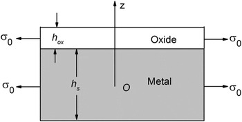
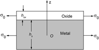
Metal oxidation at high temperature is schematically shown in Fig. 1. The external loading σexternal is applied to the system. The thicknesses of the oxidation scale and the metal substrate are h ox and h s, respectively. The origin of the system is set at the central of the substrate. Suppose that (i) the mechanical properties of the oxide scale and substrate are isotropic. (ii) Isothermal oxidation occurs on single surface of the metal. (iii) The other surface is protected by the oxide coating as described by Saunders et al. Reference Saunders, Evans, Li, Gohil and Osgerby34
A schematic of metal oxidation.

For some metals or alloys, the oxidation at high temperature is controlled by the diffusion rate of the oxygen anions and metal cations in the formed oxide scale due to the fast reaction at the gas/oxide surface or oxide/substrate interface. The oxidation kinetics (i.e., the thickness rate of the scale) relationship dependent of the oxidation stress is presented as Reference Zhang, Zhang, Tu and Xuan31
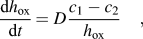 $${{{\rm{d}}{h_{{\rm{ox}}}}} \over {{\rm{d}}t}} = D{{{c_1} - {c_2}} \over {{h_{{\rm{ox}}}}}}\quad ,$$
where t is the oxidation time, D is the diffusion coefficient, c 1 and c 2 represent the vacancy concentration at the gas/oxide surface and oxide/substrate interface in the case of no stress. During the process of oxidation, diffusion coefficient D influenced by the stress in the oxide can be expressed as Reference Haftbaradaran, Gao and Curtin35,Reference Xiao, Liu, Verbrugge, Haftbaradaran and Gao36
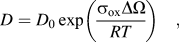 $$D = {D_0}\exp \left( {{{{\sigma _{{\rm{ox}}}}\Delta \Omega } \over {RT}}} \right)\quad ,$$
where D 0 is the diffusion coefficient independent of stress. R, T, and σox are the Boltzmann's constant, the absolute temperature and the stress in the oxide, respectively. The activation volume ΔΩ, which is associated to the Pilling–Bedworth ratio (PBR), can be expressed as Reference Evans4
 $$\Delta \Omega = \left( {{\rm{PBR}} - 1} \right) \cdot {\Omega _{\rm{m}}}\quad ,$$
where Ωm is the volume of the metal per metal ion.
Combining Eqs. (1) and (2), one obtains
 $${h_{{\rm{ox}}}}\left( t \right) = {k_{\rm{p}}}{\left[ {\int_0^t {\exp \left( {{{{\sigma _{{\rm{ox}}}}\Delta \Omega } \over {RT}}} \right)} {\rm{d}}t} \right]^{{1 \mathord{\left/ {\vphantom {1 2}} \right. \kern-\nulldelimiterspace} 2}}}$$
where
 ${k_{\rm{p}}} = \sqrt {2{D_0}\left( {{c_1} - {c_2}} \right)}$
is the oxidation kinetics constant. It is worth noticing that Eq. (3) can be simplified into the conventional parabolic form if the value of ΔΩ or σox is zero.
When the metal is exposed to the high-temperature oxidation atmosphere, the oxide scale generally grows laterally as well as thickening without the constraint of the metal substrate during the process of isothermal oxidation, as shown in Fig. 1. Meanwhile the growth strain is accompanied to occur. According to the microstructure approach proposed by Clarke,
Reference Clarke11
the lateral growth strain rate,
 ${\dot \varepsilon _{\rm{g}}}\left( t \right)$
, of the oxide scale is given as
 $${\dot \varepsilon _{\rm{g}}}\left( t \right) = {D_{{\rm{ox}}}}{\dot h_{{\rm{ox}}}}\left( t \right)\quad ,$$
where εg represents the growth strain, and D ox is the lateral growth constant. The superposed dot denotes differentiation with respect to the time.
The oxide film is adherent to the metal surface so that the oxide scale can not freely expand in the lateral direction. The substrate constraint products elastic strain and the corresponding elastic strain in the oxide scale. In addition, creep deformations will be caused to occur in both oxide and substrate. In this section, neglecting the creep deformation and taking into account the elastic strain in both the oxide and metal, and the growth strain in the oxide, in conjunction with thermal expansion strain, the total strain in the system during high-temperature oxidation is expressed as
 $${\varepsilon _{{\rm{ox}}}}(t) = \varepsilon _{{\rm{ox}}}^{\rm{e}}\left( t \right) + {\alpha _{{\rm{ox}}}}\Delta T + {\varepsilon _{\rm{g}}}(t)\quad \quad \!\!\!\!\!\!{{{h_{\rm{s}}}} \mathord{\left/ {\vphantom {{{h_{\rm{s}}}} 2}} \right. \kern-\nulldelimiterspace} 2} \;\lt\; z \;\lt\; {{{h_{\rm{s}}}} \mathord{\left/ {\vphantom {{{h_{\rm{s}}}} 2}} \right. \kern-\nulldelimiterspace} 2} + {h_{{\rm{ox}}}}$$
 $$\!\!{\varepsilon _{\rm{s}}}\left( {z,t} \right) = \varepsilon _{\rm{s}}^{\rm{e}}\left( {z,t} \right) + {\alpha _{\rm{s}}}\Delta T\quad \quad {{ - {h_{\rm{s}}}} \mathord{\left/ {\vphantom {{ - {h_{\rm{s}}}} 2}} \right. \kern-\nulldelimiterspace} 2} \;\lt\; z \;\lt\; {{{h_{\rm{s}}}} \mathord{\left/ {\vphantom {{{h_{\rm{s}}}} 2}} \right. \kern-\nulldelimiterspace} 2}\quad ,$$
where ε, εe, ΔT, and α are the total strain, elastic strain, the temperature change, and the thermal expansion coefficient, respectively.
Due to the single surface oxidation, the system will bend and the curvature can be observed. According to the plane assumption, the total strain can be given as
 $${\varepsilon _{{\rm{ox}}}}\left( t \right) = {\varepsilon _0}\left( t \right) - k\left( t \right){{{h_{\rm{s}}}} \over {\rm{2}}}\quad \quad {{{h_{\rm{s}}}} \mathord{\left/ {\vphantom {{{h_{\rm{s}}}} 2}} \right. \kern-\nulldelimiterspace} 2} \;\lt\; z \;\lt\; {{{h_{\rm{s}}}} \mathord{\left/ {\vphantom {{{h_{\rm{s}}}} 2}} \right. \kern-\nulldelimiterspace} 2} + {h_{{\rm{ox}}}}$$
 $${\varepsilon _{\rm{s}}}\left( {z,t} \right) = {\varepsilon _0}\left( t \right) - k\left( t \right)z\quad \quad {{ - {h_{\rm{s}}}} \mathord{\left/ {\vphantom {{ - {h_{\rm{s}}}} 2}} \right. \kern-\nulldelimiterspace} 2} \;\lt\; z \;\lt\; {{{h_{\rm{s}}}} \mathord{\left/ {\vphantom {{{h_{\rm{s}}}} 2}} \right. \kern-\nulldelimiterspace} 2}\quad ,$$
where ε0(t) is the lateral strain at the interface of the scale/metal system, and k(t) is the curvature of the deformed neutral axis.
In terms of the generalized Hooke's law for the equivalent biaxial stress and combining Eq. (5) with (6), the stresses in the system can be written as
 $${\sigma _{{\rm{ox}}}}\left( t \right) = {M_{{\rm{ox}}}}\left[ {{\varepsilon _0}\left( t \right) - k\left( t \right){{{h_{\rm{s}}}} \over 2} - {\alpha _{{\rm{ox}}}}\Delta T - {\varepsilon _{\rm{g}}}\left( t \right)} \right]\quad \quad \!\!\!\!\!\!{{{h_{\rm{s}}}} \mathord{\left/ {\vphantom {{{h_{\rm{s}}}} 2}} \right. \kern-\nulldelimiterspace} 2} \;\lt\; z \;\lt\; {{{h_{\rm{s}}}} \mathord{\left/ {\vphantom {{{h_{\rm{s}}}} 2}} \right. \kern-\nulldelimiterspace} 2} + {h_{{\rm{ox}}}}$$
 $${\sigma _{\rm{s}}}\left( {z,t} \right) = {M_{\rm{s}}}\left[ {{\varepsilon _0}\left( t \right) - k\left( t \right)z - {\alpha _{\rm{s}}}\Delta T} \right] \quad {{ - {h_{\rm{s}}}} \mathord{\left/ {\vphantom {{ - {h_{\rm{s}}}} 2}} \right. \kern-\nulldelimiterspace} 2} \;\lt\; z \;\lt\; {{{h_{\rm{s}}}} \mathord{\left/ {\vphantom {{{h_{\rm{s}}}} 2}} \right. \kern-\nulldelimiterspace} 2}\quad ,$$
where σ is the equi-biaxial stress of the system;
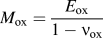 ${M_{{\rm{ox}}}} = {{{E_{{\rm{ox}}}}} \over {1 - {\nu _{{\rm{ox}}}}}}$
,
 ${M_{\rm{s}}} = {{{E_{\rm{s}}}} \over {1 - {\nu _{\rm{s}}}}}$
are the biaxial modulus; E and ν are the Young's modulus and Poisson's ratio, respectively.
To keep balance during oxidation, the following equilibrium equations of forces and moments must be satisfied:
 $$\int_{{{ - {h_{\rm{s}}}} \mathord{\left/ {\vphantom {{ - {h_{\rm{s}}}} 2}} \right. \kern-\nulldelimiterspace} 2}}^{{{{h_{\rm{s}}}} \mathord{\left/ {\vphantom {{{h_{\rm{s}}}} 2}} \right. \kern-\nulldelimiterspace} 2}} {{\sigma _{\rm{s}}}} {\rm{d}}z + {\sigma _{{\rm{ox}}}}{h_{{\rm{ox}}}} = {\sigma _{{\rm{external}}}}\left( {{h_{{\rm{ox}}}} + {h_{\rm{s}}}} \right)$$
 $$\int_{{{ - {h_{\rm{s}}}} \mathord{\left/ {\vphantom {{ - {h_{\rm{s}}}} 2}} \right. \kern-\nulldelimiterspace} 2}}^{{{{h_{\rm{s}}}} \mathord{\left/ {\vphantom {{{h_{\rm{s}}}} 2}} \right. \kern-\nulldelimiterspace} 2}} {{\sigma _{\rm{s}}}} z{\rm{d}}z + {\sigma _{{\rm{ox}}}}{h_{{\rm{ox}}}}\left( {{{{h_{\rm{s}}}} \over 2} + {{{h_{{\rm{ox}}}}} \over 2}} \right) = {\sigma _{{\rm{external}}}}{h_{{\rm{ox}}}}\left( {{{{h_{{\rm{ox}}}}} \over 2} + {{{h_{\rm{s}}}} \over 2}} \right)\quad .$$
Combining Eqs. (4), (7) and (8), the lateral strain of the central plane in the substrate, ε0, and the curvature of the system are solved as follows:
 $${\varepsilon _0}\left( t \right) = {A_1}{\varepsilon _{\rm{g}}}\left( t \right) + {A_1}{\alpha _{{\rm{ox}}}}\Delta T + {A_2}{\alpha _{\rm{s}}}\Delta T + {A_3}{\sigma _{{\rm{external}}}}$$
 $$k\left( t \right) = - {{6\left( {{h_{\rm{s}}} + {h_{{\rm{ox}}}}} \right)} \over {h_{\rm{s}}^2}}\left[ {{A_1}{\varepsilon _{\rm{g}}}\left( t \right) - {A_1}{\alpha _{\rm{s}}}\Delta T + {A_1}{\alpha _{{\rm{ox}}}}\Delta T} \right] + {A_4}{\sigma _{{\rm{external}}}}$$
with
 $${A_1} = {{{h_{\rm{s}}}{M_{{\rm{ox}}}}{h_{{\rm{ox}}}}} \over {h_{\rm{s}}^2{M_{\rm{s}}} + 4{M_{{\rm{ox}}}}{h_{{\rm{ox}}}}{h_{\rm{s}}} + 3{M_{{\rm{ox}}}}h_{{\rm{ox}}}^2}}$$
 $${A_2} = {{h_{\rm{s}}^2{M_{\rm{s}}} + 3{h_{\rm{s}}}{M_{{\rm{ox}}}}{h_{{\rm{ox}}}} + 3{M_{{\rm{ox}}}}h_{{\rm{ox}}}^2} \over {h_{\rm{s}}^2{M_{\rm{s}}} + 4{M_{{\rm{ox}}}}{h_{{\rm{ox}}}}{h_{\rm{s}}} + 3{M_{{\rm{ox}}}}h_{{\rm{ox}}}^2}} = 1 - {A_1}$$
 $${A_3} = {{{h_{\rm{s}}} + {h_{{\rm{ox}}}}} \over {{M_{\rm{s}}}}} \cdot {{{M_{\rm{s}}}{h_{\rm{s}}} + 3{M_{{\rm{ox}}}}{h_{{\rm{ox}}}}} \over {h_{\rm{s}}^2{M_{\rm{s}}} + 4{M_{{\rm{ox}}}}{h_{{\rm{ox}}}}{h_{\rm{s}}} + 3{M_{{\rm{ox}}}}h_{{\rm{ox}}}^2}}$$
 $${A_4} = {{6{h_{{\rm{ox}}}}\left( {{h_{\rm{s}}} + {h_{{\rm{ox}}}}} \right)} \over {{M_{\rm{s}}}{h_{\rm{s}}}}} \cdot {{{M_{{\rm{ox}}}} - {M_{\rm{s}}}} \over {h_{\rm{s}}^2{M_{\rm{s}}} + 4{M_{{\rm{ox}}}}{h_{{\rm{ox}}}}{h_{\rm{s}}} + 3{M_{{\rm{ox}}}}h_{{\rm{ox}}}^2}}\quad .$$
It is noted that the initial creep strain in both oxide and metal substrate are zero when t = 0. Thus, Eq. (9) can be applied to the initial condition of the following creep model for the stress evolution. This is why the creep strain is neglected in this part. It is not only an elastic model but also the initial condition of the creep model.
III. THE CREEP MODEL FOR THE STRESS EVOLUTION
Now, by the addition of the creep deformation in the oxide scale and metal substrate in Eq. (5), the total strain of the system in the creep model is expressed as
 $${\varepsilon _{{\rm{ox}}}}\left( t \right) = \varepsilon _{{\rm{ox}}}^{\rm{e}}\left( t \right) + {\alpha _{{\rm{ox}}}}\Delta T + \varepsilon _{{\rm{ox}}}^{{\rm{cr}}}\left( t \right) + {\varepsilon _{\rm{g}}}\left( t \right)$$
 $${\varepsilon _{\rm{s}}}\left( {z,t} \right) = \varepsilon _{\rm{s}}^{\rm{e}}\left( {z,t} \right) + \varepsilon _{\rm{s}}^{{\rm{cr}}}\left( {z,t} \right) + {\alpha _{\rm{s}}}\Delta T\quad ,$$
where εcr is the creep strain of the system. In terms of the Norton's law, the creep strain is expressed as
 $$\dot \varepsilon _{{\rm{ox}}}^{{\rm{cr}}} = {J_{{\rm{ox}}}}\sigma _{{\rm{ox}}}^n$$
 $$\dot \varepsilon _{\rm{s}}^{{\rm{cr}}} = {J_{\rm{s}}}\sigma _{\rm{s}}^m\quad ,$$
where J is the creep coefficient, m and n are the Norton exponents.
Based on Eqs. (6) and (11) and the generalized Hooke's law, the stress of the system becomes
 $${\sigma _{{\rm{ox}}}}\left( t \right) = {M_{{\rm{ox}}}}\varepsilon _{{\rm{ox}}}^{\rm{e}} = {M_{{\rm{ox}}}}\left[ {{\varepsilon _0}\left( t \right) - k\left( t \right){{{h_{\rm{s}}}} \over 2} - {\alpha _{{\rm{ox}}}}\Delta T - \varepsilon _{{\rm{ox}}}^{{\rm{cr}}}\left( t \right) - {\varepsilon _{\rm{g}}}\left( t \right)} \right]$$
 $${\sigma _{\rm{s}}}\left( {z,t} \right) = {M_{\rm{s}}}\varepsilon _{\rm{s}}^{\rm{e}} = {M_{\rm{s}}}\left[ {{\varepsilon _0}\left( t \right) - k\left( t \right)z - {\alpha _{\rm{s}}}\Delta T - \varepsilon _{\rm{s}}^{{\rm{cr}}}\left( t \right)} \right]\quad .$$
Differentiating Eq. (13) with respect to time, we have
 $${\dot \sigma _{{\rm{ox}}}}\left( t \right) = {M_{{\rm{ox}}}}\left[ {{{\dot \varepsilon }_0}\left( t \right) - \dot k\left( t \right){{{h_{\rm{s}}}} \over 2} - \dot \varepsilon _{{\rm{ox}}}^{{\rm{cr}}}\left( t \right) - {{\dot \varepsilon }_{\rm{g}}}\left( t \right)} \right]$$
 $${\dot \sigma _{\rm{s}}}\left( {z,t} \right) = {M_{\rm{s}}}\left[ {{{\dot \varepsilon }_0}\left( t \right) - \dot k\left( t \right)z - \dot \varepsilon _{\rm{s}}^{{\rm{cr}}}\left( t \right)} \right]\quad .$$
For the external oxidation, the substrate thickness is independent of time, differentiation of Eq. (8) gives
 $$\int_{{{ - {h_{\rm{s}}}} \mathord{\left/ {\vphantom {{ - {h_{\rm{s}}}} 2}} \right. \kern-\nulldelimiterspace} 2}}^{{{{h_{\rm{s}}}} \mathord{\left/ {\vphantom {{{h_{\rm{s}}}} 2}} \right. \kern-\nulldelimiterspace} 2}} {{{\dot \sigma }_{\rm{s}}}} {\rm{d}}z + {\dot \sigma _{{\rm{ox}}}}{h_{{\rm{ox}}}} + {\sigma _{{\rm{ox}}}}{\dot h_{{\rm{ox}}}} = {\sigma _{{\rm{external}}}}{\dot h_{{\rm{ox}}}}$$
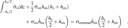 $$\int_{{{ - {h_{\rm{s}}}} \mathord{\left/ {\vphantom {{ - {h_{\rm{s}}}} 2}} \right. \kern-\nulldelimiterspace} 2}}^{{{{h_{\rm{s}}}} \mathord{\left/ {\vphantom {{{h_{\rm{s}}}} 2}} \right. \kern-\nulldelimiterspace} 2}} {{{\dot \sigma }_{\rm{s}}}} z{\rm{d}}z + {1 \over 2}{\dot \sigma _{{\rm{ox}}}}{h_{{\rm{ox}}}}\left( {{h_{\rm{s}}} + {h_{{\rm{ox}}}}} \right) + {\sigma _{{\rm{ox}}}}{\dot h_{{\rm{ox}}}}\left( {{{{h_{\rm{s}}}} \over 2} + {h_{{\rm{ox}}}}} \right) = {\sigma _{{\rm{external}}}}{\dot h_{{\rm{ox}}}}\left( {{{{h_{\rm{s}}}} \over 2} + {h_{{\rm{ox}}}}} \right)\quad .$$
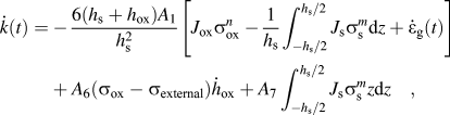
Combining Eq. (4) with (12), and then substituting Eq. (14) into (15), we have
 $${\dot \varepsilon _{\rm{0}}}\left( t \right) = {A_1}\left[ {{J_{{\rm{ox}}}}\sigma _{{\rm{ox}}}^n + {{\dot \varepsilon }_{\rm{g}}}\left( t \right)} \right] + {{{A_2}} \over {{h_{\rm{s}}}}}\int_{{{ - {h_{\rm{s}}}} \mathord{\left/ {\vphantom {{ - {h_{\rm{s}}}} 2}} \right. \kern-\nulldelimiterspace} 2}}^{{{{h_{\rm{s}}}} \mathord{\left/ {\vphantom {{{h_{\rm{s}}}} 2}} \right. \kern-\nulldelimiterspace} 2}} {{J_{\rm{s}}}\sigma _{\rm{s}}^m} {\rm{d}}z - {{6{A_1}} \over {h_{\rm{s}}^2}}\int_{{{ - {h_{\rm{s}}}} \mathord{\left/ {\vphantom {{ - {h_{\rm{s}}}} 2}} \right. \kern-\nulldelimiterspace} 2}}^{{{{h_{\rm{s}}}} \mathord{\left/ {\vphantom {{{h_{\rm{s}}}} 2}} \right. \kern-\nulldelimiterspace} 2}} {{J_{\rm{s}}}\sigma _{\rm{s}}^m} z{\rm{d}}z + {{{A_5}} \over {{M_{\rm{s}}}{h_{\rm{s}}}}}\left( {{\sigma _{{\rm{ox}}}} - {\sigma _{{\rm{external}}}}} \right){\dot h_{{\rm{ox}}}}$$
 $$\dot k\left( t \right) = - {{6\left( {{h_{\rm{s}}} + {h_{{\rm{ox}}}}} \right){A_1}} \over {h_{\rm{s}}^2}}\left[ {{J_{{\rm{ox}}}}\sigma _{{\rm{ox}}}^n - {1 \over {{h_{\rm{s}}}}}\int_{{{ - {h_{\rm{s}}}} \mathord{\left/ {\vphantom {{ - {h_{\rm{s}}}} 2}} \right. \kern-\nulldelimiterspace} 2}}^{{{{h_{\rm{s}}}} \mathord{\left/ {\vphantom {{{h_{\rm{s}}}} 2}} \right. \kern-\nulldelimiterspace} 2}} {{J_{\rm{s}}}\sigma _{\rm{s}}^m} {\rm{d}}z + {{\dot \varepsilon }_{\rm{g}}}\left( t \right)} \right] + {A_6}\left( {{\sigma _{{\rm{ox}}}} - {\sigma _{{\rm{external}}}}} \right){\dot h_{{\rm{ox}}}} + {A_7}\int_{{{ - {h_{\rm{s}}}} \mathord{\left/ {\vphantom {{ - {h_{\rm{s}}}} 2}} \right. \kern-\nulldelimiterspace} 2}}^{{{{h_{\rm{s}}}} \mathord{\left/ {\vphantom {{{h_{\rm{s}}}} 2}} \right. \kern-\nulldelimiterspace} 2}} {{J_{\rm{s}}}\sigma _{\rm{s}}^m} z{\rm{d}}z\quad ,$$
where
 $${A_5} = {{3{M_{{\rm{ox}}}}h_{{\rm{ox}}}^{\rm{2}} - {M_{\rm{s}}}h_{\rm{s}}^2} \over {{M_{\rm{s}}}h_{\rm{s}}^2 + 4{M_{{\rm{ox}}}}{h_{{\rm{ox}}}}{h_{\rm{s}}} + 3{M_{{\rm{ox}}}}h_{{\rm{ox}}}^2}}$$
 $${A_6} = {{6\left( {h_{\rm{s}}^{\rm{2}}{M_{\rm{s}}} + 2{M_{\rm{s}}}{h_{{\rm{ox}}}}{h_{\rm{s}}} + {M_{{\rm{ox}}}}h_{{\rm{ox}}}^2} \right)} \over {{M_{\rm{s}}}h_{\rm{s}}^2\left( {h_{\rm{s}}^2{M_{\rm{s}}} + 4{M_{{\rm{ox}}}}{h_{{\rm{ox}}}}{h_{\rm{s}}} + 3{M_{{\rm{ox}}}}h_{{\rm{ox}}}^2} \right)}}$$
 $${A_7} = {{ - 12\left( {{M_{{\rm{ox}}}}{h_{{\rm{ox}}}} + {M_{\rm{s}}}{h_{\rm{s}}}} \right)} \over {h_{\rm{s}}^2\left( {h_{\rm{s}}^2{M_{\rm{s}}} + 4{M_{{\rm{ox}}}}{h_{{\rm{ox}}}}{h_{\rm{s}}} + 3{M_{{\rm{ox}}}}h_{{\rm{ox}}}^2} \right)}}\quad .$$
The stresses in the oxide and the substrate can be calculated by adopting the Euler method, that is
 $${\sigma _{{\rm{ox}}}}\left( {t + \Delta t} \right) = {\sigma _{{\rm{ox}}}}\left( t \right) + {\dot \sigma _{{\rm{ox}}}}\left( {t + \Delta t} \right) \cdot \Delta t$$
 $${\sigma _{\rm{s}}}\left( {z,t + \Delta t} \right) = {\sigma _{\rm{s}}}\left( {z,t} \right) + {\dot \sigma _{\rm{s}}}\left( {z,t + \Delta t} \right) \cdot \Delta t\quad .$$
The curvature of the system satisfies
 $$k\left( {t + \Delta t} \right) = k\left( t \right) + \dot k\left( {t + \Delta t} \right) \cdot \Delta t\quad .$$
Substitution of Eqs. (14) and (16) into (18) gives
 $${\sigma _{{\rm{ox}}}}\left| {_{t + \Delta t}} \right. = {\sigma _{{\rm{ox}}}}\left| {_t} \right. + {M_{{\rm{ox}}}}\left( {{{\dot \varepsilon }_0}\left| {_{t + \Delta t}} \right. - \dot k\left| {_{t + \Delta t}} \right.{{{h_{\rm{s}}}} \over 2} - \dot \varepsilon _{{\rm{ox}}}^{{\rm{cr}}}\left| {_{t + \Delta t}} \right. - {{\dot \varepsilon }_{\rm{g}}}\left| {_{t + \Delta t}} \right.} \right) \cdot \Delta t$$
 $${\sigma _{\rm{s}}}\left| {_{t + \Delta t}} \right. = {\sigma _{\rm{s}}}\left| {_t} \right. + {M_{\rm{s}}}\left( {{{\dot \varepsilon }_0}\left| {_{t + \Delta t}} \right. - \dot k\left| {_{t + \Delta t}} \right.z - \dot \varepsilon _{\rm{s}}^{{\rm{cr}}}\left| {_{t + \Delta t}} \right.} \right) \cdot \Delta t\quad .$$
Equations (16) and (20) are made up of the stress evolution and curvature variation equations.
For simplification, we suppose that the Norton exponents of the system are equal to 1, i.e., m = n = 1, which is also done by Panicaud et al., Reference Panicaud, Grosseau-Poussard and Dinhut24 and Dong et al. Reference Dong, Feng and Hwang33 Then Eq. (14) becomes
 $${\dot \sigma _{{\rm{ox}}}}\left( t \right) = {M_{{\rm{ox}}}}\left[ {{{\dot \varepsilon }_0}\left( t \right) - \dot k\left( t \right){{{h_{\rm{s}}}} \over 2} - {J_{{\rm{ox}}}}{\sigma _{{\rm{ox}}}} - {{\dot \varepsilon }_{\rm{g}}}\left( t \right)} \right]$$
 $${\dot \sigma _{\rm{s}}}\left( {z,t} \right) = {M_{\rm{s}}}\left[ {{{\dot \varepsilon }_0}\left( t \right) - \dot k\left( t \right)z - {J_{\rm{s}}}{\sigma _{\rm{s}}}} \right]\quad .$$
Combining Eq. (21) with (15), one obtains
 $${M_{\rm{s}}}\left[ {{{\dot \varepsilon }_0}\left( t \right){h_{\rm{s}}} - \int_{{{ - {h_{\rm{s}}}} \mathord{\left/ {\vphantom {{ - {h_{\rm{s}}}} 2}} \right. \kern-\nulldelimiterspace} 2}}^{{{{h_{\rm{s}}}} \mathord{\left/ {\vphantom {{{h_{\rm{s}}}} 2}} \right. \kern-\nulldelimiterspace} 2}} {{J_{\rm{s}}}{\sigma _{\rm{s}}}} {\rm{d}}z} \right] + {\dot \sigma _{{\rm{ox}}}}{h_{{\rm{ox}}}} + {\sigma _{{\rm{ox}}}}{\dot h_{{\rm{ox}}}} = {\sigma _{{\rm{external}}}}{\dot h_{{\rm{ox}}}}$$
 $${M_{\rm{s}}}\left[ { - {1 \over {12}}\dot k\left( t \right)h_{\rm{s}}^3 - \int_{{{ - {h_{\rm{s}}}} \mathord{\left/ {\vphantom {{ - {h_{\rm{s}}}} 2}} \right. \kern-\nulldelimiterspace} 2}}^{{{{h_{\rm{s}}}} \mathord{\left/ {\vphantom {{{h_{\rm{s}}}} 2}} \right. \kern-\nulldelimiterspace} 2}} {{J_{\rm{s}}}{\sigma _{\rm{s}}}} z{\rm{d}}z} \right] + {1 \over 2}{\dot \sigma _{{\rm{ox}}}}{h_{{\rm{ox}}}}\left( {{h_{\rm{s}}} + {h_{{\rm{ox}}}}} \right) + {\sigma _{{\rm{ox}}}}\left( {{{{h_{\rm{s}}}} \over 2} + {h_{{\rm{ox}}}}} \right){\dot h_{{\rm{ox}}}} = {\sigma _{{\rm{external}}}}\left( {{{{h_{\rm{s}}}} \over 2} + {h_{{\rm{ox}}}}} \right){\dot h_{{\rm{ox}}}}\quad .$$
The balance Eq. (8) can be converted as
 $$- \int_{{{ - {h_{\rm{s}}}} \mathord{\left/ {\vphantom {{ - {h_{\rm{s}}}} 2}} \right. \kern-\nulldelimiterspace} 2}}^{{{{h_{\rm{s}}}} \mathord{\left/ {\vphantom {{{h_{\rm{s}}}} 2}} \right. \kern-\nulldelimiterspace} 2}} {{J_{\rm{s}}}{\sigma _{\rm{s}}}} {\rm{d}}z = {J_{\rm{s}}}{\sigma _{{\rm{ox}}}}{h_{{\rm{ox}}}} - {J_{\rm{s}}}{\sigma _{{\rm{external}}}}{1 \over 2}\left( {{h_{{\rm{ox}}}} + {h_{\rm{s}}}} \right)$$
 $$- \int_{{{ - {h_{\rm{s}}}} \mathord{\left/ {\vphantom {{ - {h_{\rm{s}}}} 2}} \right. \kern-\nulldelimiterspace} 2}}^{{{{h_{\rm{s}}}} \mathord{\left/ {\vphantom {{{h_{\rm{s}}}} 2}} \right. \kern-\nulldelimiterspace} 2}} {{J_{\rm{s}}}{\sigma _{\rm{s}}}} z{\rm{d}}z = {1 \over 2}{J_{\rm{s}}}{\sigma _{{\rm{ox}}}}{h_{{\rm{ox}}}}\left( {{h_{\rm{s}}} + {h_{{\rm{ox}}}}} \right) - {1 \over 2}{J_{\rm{s}}}{\sigma _{{\rm{external}}}}{h_{{\rm{ox}}}}\left( {{h_{\rm{s}}} + {h_{{\rm{ox}}}}} \right)\quad .$$
By combining the above equations with Eq. (22), we obtain
 $${M_{\rm{s}}}{\dot \varepsilon _0}\left( t \right){h_{\rm{s}}} + {M_{\rm{s}}}{J_{\rm{s}}}{\sigma _{{\rm{ox}}}}{h_{{\rm{ox}}}} - {M_{\rm{s}}}{J_{\rm{s}}}{\sigma _{{\rm{external}}}}{1 \over 2}\left( {{h_{{\rm{ox}}}} + {h_{\rm{s}}}} \right) + {\dot \sigma _{{\rm{ox}}}}{h_{{\rm{ox}}}} + {\sigma _{{\rm{ox}}}}{\dot h_{{\rm{ox}}}} = {\sigma _{{\rm{external}}}}{\dot h_{{\rm{ox}}}}$$
 $$- {1 \over 6}{M_{\rm{s}}}\dot k\left( t \right)h_{\rm{s}}^3 + {M_{\rm{s}}}{J_{\rm{s}}}\left( {{\sigma _{{\rm{ox}}}} - {\sigma _{{\rm{external}}}}} \right){h_{{\rm{ox}}}}\left( {{h_{\rm{s}}} + {h_{{\rm{ox}}}}} \right) + {\dot \sigma _{{\rm{ox}}}}{h_{{\rm{ox}}}}\left( {{h_{\rm{s}}} + {h_{{\rm{ox}}}}} \right) + \left( {{\sigma _{{\rm{ox}}}} - {\sigma _{{\rm{external}}}}} \right)\left( {{h_{\rm{s}}} + 2{h_{{\rm{ox}}}}} \right){\dot h_{{\rm{ox}}}} = 0\quad .$$
Equation (23) can be rewritten as
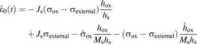 $${\dot \varepsilon _0}\left( t \right) = - {J_{\rm{s}}}\left( {{\sigma _{{\rm{ox}}}} - {\sigma _{{\rm{external}}}}} \right){{{h_{{\rm{ox}}}}} \over {{h_{\rm{s}}}}} + {J_{\rm{s}}}{\sigma _{{\rm{external}}}} - {\dot \sigma _{{\rm{ox}}}}{{{h_{{\rm{ox}}}}} \over {{M_{\rm{s}}}{h_{\rm{s}}}}} - \left( {{\sigma _{{\rm{ox}}}} - {\sigma _{{\rm{external}}}}} \right){{{{\dot h}_{{\rm{ox}}}}} \over {{M_{\rm{s}}}{h_{\rm{s}}}}}$$
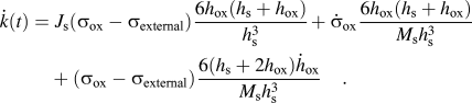 $$\dot k\left( t \right) = \;{J_{\rm{s}}}\left( {{\sigma _{{\rm{ox}}}} - {\sigma _{{\rm{external}}}}} \right){{6{h_{{\rm{ox}}}}\left( {{h_{\rm{s}}} + {h_{{\rm{ox}}}}} \right)} \over {h_{\rm{s}}^3}} + {\dot \sigma _{{\rm{ox}}}}{{6{h_{{\rm{ox}}}}\left( {{h_{\rm{s}}} + {h_{{\rm{ox}}}}} \right)} \over {{M_{\rm{s}}}h_{\rm{s}}^3}} + \left( {{\sigma _{{\rm{ox}}}} - {\sigma _{{\rm{external}}}}} \right){{6\left( {{h_{\rm{s}}} + 2{h_{{\rm{ox}}}}} \right){{\dot h}_{{\rm{ox}}}}} \over {{M_{\rm{s}}}h_{\rm{s}}^3}}\quad .$$
Combining Eq. (24) with (14), the stress evolution equations for the oxide scale and the metal substrate are obtained as follows:
 $$\left( {{{{M_{\rm{s}}}h_{\rm{s}}^2} \over {{M_{{\rm{ox}}}}}} + 4{h_{\rm{s}}}{h_{{\rm{ox}}}} + 3h_{{\rm{ox}}}^2} \right){\dot \sigma _{{\rm{ox}}}} + \left[ {2\left( {2{h_{\rm{s}}} + 3{h_{{\rm{ox}}}}} \right){{\dot h}_{{\rm{ox}}}} + {M_{\rm{s}}}{J_{\rm{s}}}{h_{{\rm{ox}}}}\left( {4{h_{\rm{s}}} + 3{h_{{\rm{ox}}}}} \right)} \right]\left( {{\sigma _{{\rm{ox}}}} - {\sigma _{{\rm{external}}}}} \right) + {J_{{\rm{ox}}}}{M_{\rm{s}}}h_{\rm{s}}^2{\sigma _{{\rm{ox}}}} = - {M_{\rm{s}}}{D_{{\rm{ox}}}}h_{\rm{s}}^2{\dot h_{{\rm{ox}}}}$$$${\dot \sigma _{\rm{s}}} + {M_{\rm{s}}}{J_{\rm{s}}}{\sigma _{\rm{s}}} = - {M_{\rm{s}}}\left[ {{J_{\rm{s}}}\left( {{\sigma _{{\rm{ox}}}} - {\sigma _{{\rm{external}}}}} \right){{{h_{{\rm{ox}}}}} \over {{h_{\rm{s}}}}} + {{\dot \sigma }_{{\rm{ox}}}}{{{h_{{\rm{ox}}}}} \over {{M_{\rm{s}}}{h_{\rm{s}}}}} + \left( {{\sigma _{{\rm{ox}}}} - {\sigma _{{\rm{external}}}}} \right){{{{\dot h}_{{\rm{ox}}}}} \over {{M_{\rm{s}}}{h_{\rm{s}}}}} - {J_{\rm{s}}}{\sigma _{{\rm{external}}}}} \right] - {M_{\rm{s}}}z\left[ {{J_{\rm{s}}}\left( {{\sigma _{{\rm{ox}}}} - {\sigma _{{\rm{external}}}}} \right){{6{h_{{\rm{ox}}}}\left( {{h_{\rm{s}}} + {h_{{\rm{ox}}}}} \right)} \over {h_{\rm{s}}^3}} + {{\dot \sigma }_{{\rm{ox}}}}{{6{h_{{\rm{ox}}}}\left( {{h_{\rm{s}}} + {h_{{\rm{ox}}}}} \right)} \over {{M_{\rm{s}}}h_{\rm{s}}^3}} + \left( {{\sigma _{{\rm{ox}}}} - {\sigma _{{\rm{external}}}}} \right){{6\left( {{h_{\rm{s}}} + 2{h_{{\rm{ox}}}}} \right){{\dot h}_{{\rm{ox}}}}} \over {{M_{\rm{s}}}h_{\rm{s}}^3}}} \right]\quad .$$
IV. RESULTS AND DISCUSSIONS
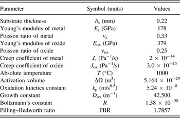
To verify the proposed models, FeCrAlY oxidation is discussed at 1000 °C and the parameters for the calculation are listed in Table I.
Value of some material parameters as in Refs. Reference Maharjan, Zhang and Wang10, Reference Dong, Feng and Hwang33, and Reference Saunders, Evans, Li, Gohil and Osgerby34.

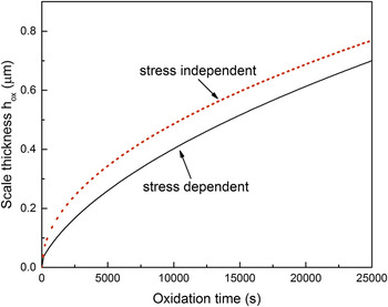
Figure 2 depicts the relationship of the oxide thickness and time with the stress effect (solid line) and without the stress effect (dash line). It is obviously seen that the oxidation rate with the stress effect becomes smaller than that without the stress effect, which is because the compressive stress in the scale decreases the diffusion rate according to Eq. (2), and then reduces the chemical reaction. Slower chemical reaction results in slower growth of the scale thickness. This result can also be observed in the experiment. Reference Hay37
The comparison of the oxidation kinetics.

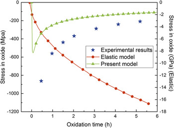
To compare the proposed model with experimental data Reference Saunders, Evans, Li, Gohil and Osgerby34 and the elastic model, Reference Dong, Feng and Hwang33 we request the external loading σexternal to be zero. The stress evolution in the oxide is plotted in Fig. 3. It is seen from Fig. 3 that the stress in oxide of the present model has similar trend to the experiment results of Saunders et al. Reference Saunders, Evans, Li, Gohil and Osgerby34 That is, the stress decreases gradually with the increasing of oxidation time when the oxidation time is larger. However, the stress in oxide dramatically deviates from the experimental results Reference Saunders, Evans, Li, Gohil and Osgerby34 in magnitude and increases with the oxidation time in the elastic model. Reference Dong, Feng and Hwang33 Moreover, the order of the stress in elastic model reaches ∼GPa. On the other hand, the present model exhibits the sharp increase of the oxide stress and there is no experimental data to publish for FeCrAlY oxidation at the initial stage of oxidation, which shows that the present model gives a better approximate stress evolution trend in the oxide scale.
The comparison of the stress in oxide.

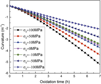
The effect of external loading on the curvature of the system is shown in Fig. 4. The curvature gradually increases as the oxidation time elapses. When the external loading changes from compressive to tensile, the curvature of the system becomes larger and larger which indicates that it is easier to bend for the tensile external loading.
Effect of external loading on the curvature of system.

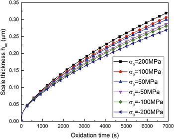
Figure 5 shows the effect of external loading on the variations of oxide scale thickness (the growth rate). With the increasing oxidation time, the thickness of the oxide film gradually increases and the growth rate decreases, constant whatever the external loading is. It can be seen that the compressive external loading reduces the scale thickness significantly as given in Ref. Reference Evans, Norfolk and Swan38 while the tensile external loading increases it as shown in Ref. Reference Tolpygo and Clarke39 and Reference Calvarin-Amiri, Huntz and Molins40. Moreover, the larger the thickness rate is, the larger tensile external loading is, and the smaller the thickness rate is, the larger compressive external loading in magnitude is. Compared with the scale thickness at the same time, it is observed that the thickness of the film becomes smaller and smaller when the external loading changes from the tensile stress to compressive stress which has also been verified in experiments. Reference Hay37,Reference Gauthier, Pailler, Lamon and Pailler41
Effect of external loading on the scale thickness.

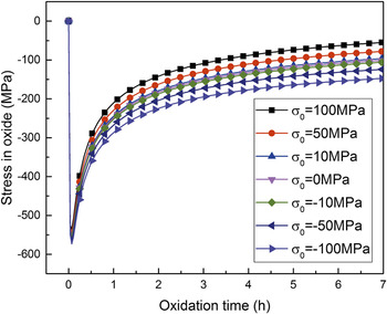
The variation of the oxide stress in magnitude is also obviously affected by the external loading, as seen in Fig. 6. The stress in the scale is always compressive no matter whether the external loading is tensile or compressive. The oxide stress exhibits a rapid increase at the beginning of the oxidation stage no matter what the external loading is. After the peak, the stress will decrease in magnitude. However, the oxide stress will increase in magnitude when the external loading varies from 100 to −100 MPa. That is, the compressive external loading increases the oxide stress in magnitude while the tensile one decreases it at longer oxidation time. These show that the external loading can control the magnitude of the stress in the oxidation film. Therefore, one may put the tensile external loading to the metal substrate to reduce the oxidation stress.
Effect of external loading on the oxide stress.

V. CONCLUSIONS
Based on the balance equations of forces and moments, a stress evolution model during the metallic oxidation at high temperature is developed by considering the external loading, bending deformation, stress-dependent kinetic relationship. This model exhibits the curvature changes caused by the bending deformation. For FeCrAlY oxidation, the comparison of the oxidation kinetics between stress-dependent and the stress-independent (the parabolic law) is made and results show that the stress reduces the oxidation kinetics. Then the influences of the external loading upon the stress distribution in the oxide scale, the scale thickness and the curvature of the system are investigated, and numerical results show that the tensile external loading decreases the oxidation stress in magnitude while it promotes the growth rate of oxidation layer.
ACKNOWLEDGMENTS
The supports from NSFC (Grants No. 11402054, 11201277), Natural Science Basic Research Plan in Shaanxi Province of China (No. 2015JM1011, 2016JQ1032), Scientific Research Program Funded by Shaanxi Provincial Education Commission (No. 16Jk1504) and Project Funded by China Postdoctoral Science Foundation (No. 2015M570552) are appreciated.