








1. Introduction
The mechanisms of electron heating and acceleration in collisionless shock waves are still not entirely resolved (e.g. Ghavamian et al. Reference Ghavamian, Schwartz, Mitchell, Masters and Laming2013; Krasnoselskikh et al. Reference Krasnoselskikh, Balikhin, Walker, Schwartz, Sundkvist, Lobzin, Gedalin, Bale, Mozer and Soucek2013; Amano et al. Reference Amano, Matsumoto, Bohdan, Kobzar, Matsukiyo, Oka, Niemiec, Pohl and Hoshino2022). The understanding of these mechanisms would substantially advance the interpretation of remote observations of astrophysical shocks in supernova remnants and galaxy clusters (Markevitch & Vikhlinin Reference Markevitch and Vikhlinin2007; Ghavamian et al. Reference Ghavamian, Schwartz, Mitchell, Masters and Laming2013; Raymond et al. Reference Raymond, Ghavamian, Bohdan, Ryu, Niemiec, Sironi, Tran, Amato, Hoshino and Pohl2023). Even though the Earth's bow shock is not identical to astrophysical shocks, it is still a perfect natural laboratory for probing plasma processes around supercritical collisionless shocks using in situ observations. The early spacecraft measurements in the Earth's bow shock demonstrated that the macroscopic electric field, which occurs because of different electron and ion dynamics, should provide a leading contribution to the electron heating (Scudder Reference Scudder1995). The modern spacecraft measurements showed, however, that electron heating is typically non-adiabatic (Gedalin et al. Reference Gedalin, Golan, Vink, Ganushkina and Balikhin2023; Johlander et al. Reference Johlander, Khotyaintsev, Dimmock, Graham and Lalti2023) and revealed electron acceleration up to tens of keV (Gosling et al. Reference Gosling, Thomsen, Bame and Russell1989; Oka et al. Reference Oka, Terasawa, Seki, Fujimoto, Kasaba, Kojima, Shinohara, Matsui, Matsumoto and Saito2006). The non-adiabatic heating and superthermal electrons indicate that electric and magnetic field fluctuations must be involved in electron heating and acceleration processes in collisionless shocks. According to numerical simulations, electron pitch-angle scattering produced by electric and magnetic field fluctuations observed in the Earth's bow shock can indeed result in non-adiabatic heating (Vasko et al. Reference Vasko, Mozer, Krasnoselskikh, Artemyev, Agapitov, Bale, Avanov, Ergun, Giles and Lindqvist2018b; Oka et al. Reference Oka, Otsuka, Matsukiyo, Wilson, Argall, Amano, Phan, Hoshino, Le Contel and Gershman2019; Gedalin Reference Gedalin2020; Artemyev et al. Reference Artemyev, Shi, Liu, Zhang, Vasko and Angelopoulos2022) and acceleration through the stochastic shock drift acceleration (SSDA) mechanism (Amano et al. Reference Amano, Katou, Kitamura, Oka, Matsumoto, Hoshino, Saito, Yokota, Giles and Paterson2020, Reference Amano, Matsumoto, Bohdan, Kobzar, Matsukiyo, Oka, Niemiec, Pohl and Hoshino2022). The contribution of different electric and magnetic field fluctuations to electron heating and acceleration processes around collisionless shocks is currently actively investigated.
Spacecraft measurements revealed various electromagnetic and electrostatic fluctuations in the Earth's bow shock (e.g. Gurnett Reference Gurnett1985; Wilson et al. Reference Wilson, Sibeck, Breneman, Contel, Cully, Turner, Angelopoulos and Malaspina2014). The most intense among the electromagnetic fluctuations are fast magnetosonic and whistler-mode waves produced by, respectively, ion and electron instabilities (Oka et al. Reference Oka, Wilson, Phan, Hull, Amano, Hoshino, Argall, Le Contel, Agapitov and Gershman2017, Reference Oka, Otsuka, Matsukiyo, Wilson, Argall, Amano, Phan, Hoshino, Le Contel and Gershman2019; Page et al. Reference Page, Vasko, Artemyev and Bale2021; Lalti et al. Reference Lalti, Khotyaintsev, Graham, Vaivads, Steinvall and Russell2022). The electrostatic fluctuations typically have broadband power spectra and, particularly, consist of electrostatic solitary waves and wave packets interpreted in terms of, respectively, ion or electron phase space holes and ion-acoustic waves (Fuselier & Gurnett Reference Fuselier and Gurnett1984; Balikhin et al. Reference Balikhin, Walker, Treumann, Alleyne, Krasnoselskikh, Gedalin, Andre, Dunlop and Fazakerley2005; Hull et al. Reference Hull, Larson, Wilber, Scudder, Mozer, Russell and Bale2006; Vasko et al. Reference Vasko, Wang, Mozer, Bale and Artemyev2020, Reference Vasko, Mozer, Bale and Artemyev2022; Wang et al. Reference Wang, Vasko, Mozer, Bale, Artemyev, Bonnell, Ergun, Giles, Lindqvist and Russell2020, Reference Wang, Vasko, Mozer, Bale, Kuzichev, Artemyev, Steinvall, Ergun, Giles and Khotyaintsev2021; Kamaletdinov et al. Reference Kamaletdinov, Vasko, Wang, Artemyev, Yushkov and Mozer2022). Note that electron cyclotron harmonics coupled with ion-acoustic waves also contribute to electrostatic fluctuations in the Earth's bow shock (Breneman et al. Reference Breneman, Cattell, Kersten, Paradise, Schreiner, Kellogg, Goetz and Wilson2013; Wilson et al. Reference Wilson, Sibeck, Breneman, Contel, Cully, Turner, Angelopoulos and Malaspina2014; Muschietti & Lembège Reference Muschietti and Lembège2017). The recent analysis of spacecraft measurements around the Earth's quasi-perpendicular bow shock showed that superthermal electron fluxes up to a few tens of keV can be produced through the SSDA mechanism with pitch-angle scattering provided by electromagnetic fluctuations (Amano et al. Reference Amano, Katou, Kitamura, Oka, Matsumoto, Hoshino, Saito, Yokota, Giles and Paterson2020). While the electromagnetic fluctuations can indeed provide efficient scattering of thermal and superthermal electrons, recent theoretical computations demonstrated that pitch-angle scattering by electrostatic fluctuations can also be efficient below approximately 1 keV (Vasko et al. Reference Vasko, Mozer, Krasnoselskikh, Artemyev, Agapitov, Bale, Avanov, Ergun, Giles and Lindqvist2018b; Kamaletdinov et al. Reference Kamaletdinov, Vasko, Artemyev, Wang and Mozer2022). In particular, the computations showed that pitch-angle scattering by electrostatic solitary waves can result in acceleration of thermal electrons up to a few hundred eV provided that the observed electrostatic wave power corresponds solely to these electrostatic structures (Kamaletdinov et al. Reference Kamaletdinov, Vasko, Artemyev, Wang and Mozer2022). In reality, electrostatic solitary waves have a relatively low occurrence and the observed electrostatic wave power in the Earth's bow shock is predominantly due to electrostatic wave packets (Breneman et al. Reference Breneman, Cattell, Kersten, Paradise, Schreiner, Kellogg, Goetz and Wilson2013; Wang et al. Reference Wang, Vasko, Mozer, Bale, Artemyev, Bonnell, Ergun, Giles, Lindqvist and Russell2020, Reference Wang, Vasko, Mozer, Bale, Kuzichev, Artemyev, Steinvall, Ergun, Giles and Khotyaintsev2021; Vasko et al. Reference Vasko, Wang, Mozer, Bale and Artemyev2020, Reference Vasko, Mozer, Bale and Artemyev2022). This stimulates the present analysis of electron pitch-angle scattering by electrostatic wave packets present in the Earth's bow shock and, presumably, collisionless shocks in general.
The recent measurements aboard the Magnetospheric Multiscale spacecraft (Burch et al. Reference Burch, Moore, Torbert and Giles2016) have allowed the most detailed analysis of electrostatic fluctuations in the Earth's bow shock. Figure 1 demonstrates several electrostatic wave packets observed aboard the Magnetospheric Multiscale spacecraft around the ramp of the Earth's quasi-perpendicular bow shock. The bottom panels demonstrate electrostatic wave packets with amplitudes up to a few hundred mV m$^{-1}$ , plasma frame speeds of approximately a hundred km s$^{-1}$
 , which is around the local ion-acoustic speed, and typical wavelengths of approximately a few hundred metres, which is approximately a few tens of local Debye lengths. Importantly, these electrostatic wave packets have the electric field oriented quasi-parallel, oblique or quasi-perpendicular to the local magnetic field and amplitudes of the electrostatic potential of up to a few tens of volts, which is approximately 1 %–20 % of the local electron temperature. Similar properties are actually typical of all other electrostatic wave packets observed in this Earth bow shock crossing (Vasko et al. Reference Vasko, Mozer, Bale and Artemyev2022): wavelengths from a few tens to a few hundred Debye lengths, amplitudes of a substantial fraction of the local electron temperature and electric fields oriented at arbitrary angles to the local magnetic field. Quantifying electron scattering by these electrostatic fluctuations is not elementary, since quasi-linear theory may not be applicable for the observed large amplitudes (e.g. Omura et al. Reference Omura, Matsumoto, Nunn and Rycroft1991, Reference Omura, Miyashita, Yoshikawa, Summers, Hikishima, Ebihara and Kubota2015; Albert, Meredith & Horne Reference Albert, Meredith and Horne2009; Shklyar & Matsumoto Reference Shklyar and Matsumoto2009).
The demonstration of electrostatic wave packets observed on 4 November 2015 aboard the Magnetospheric Multiscale spacecraft around the Earth's quasi-perpendicular bow shock (only MMS3 measurements are shown here): (a) the magnetic field magnitude measured at 128 Samples s$^{-1}$ by digital and analogue fluxgate magnetometers (Russell et al. Reference Russell, Anderson, Baumjohann, Bromund, Dearborn, Fischer, Le, Leinweber, Leneman and Magnes2016), (b) electron density and (c) electron temperatures (parallel and perpendicular) measured at 30 ms resolution by the Fast Plasma Investigation instrument (Pollock et al. Reference Pollock, Moore, Jacques, Burch, Gliese, Saito, Omoto, Avanov, Barrie and Coffey2016), (d–f) electric field waveforms of electrostatic wave packets propagating at different angles to the local magnetic field, where electric field measurements are provided at 8192 samples s$^{-1}$
 by the axial double probe (Ergun et al. Reference Ergun, Tucker, Westfall, Goodrich, Malaspina, Summers, Wallace, Karlsson, Mack and Brennan2016) and spin-plane double probe (Lindqvist et al. Reference Lindqvist, Olsson, Torbert, King, Granoff, Rau, Needell, Turco, Dors and Beckman2016). For each wave packet we present the electric field in local magnetic field-aligned coordinates and the electrostatic potential computed by integrating over time the electric field multiplied by the wave propagation velocity in the spacecraft frame. The bottom axes in panels (d–f) convert temporal scale into spatial scale by multiplying with the revealed propagation velocity. Note that the spacecraft frame velocities of these waves were estimated using measurements of the double-probe instrument aboard the Magnetospheric Multiscale spacecraft. The corresponding methodology and a more detailed analysis of this Earth bow shock crossing can be found in Vasko et al. (Reference Vasko, Mozer, Bale and Artemyev2022). In panels (d–f) we also present the plasma frame speed $V_{{\rm ph}}$
 , wave normal angle $\theta$
 with respect to the local magnetic field and typical wavelength $\lambda$
 in units of local electron Debye length $\lambda _{D}$
 .

In this study we apply a probabilistic approach (Artemyev et al. Reference Artemyev, Neishtadt, Vasiliev and Mourenas2021; Lukin, Artemyev & Petrukovich Reference Lukin, Artemyev and Petrukovich2021; Zhang et al. Reference Zhang, Artemyev, Angelopoulos, Tsai, Wilkins, Kasahara, Mourenas, Yokota, Keika and Hori2022) to quantify electron scattering by electrostatic fluctuations reported in the Earth's bow shock and demonstrate that electron pitch-angle scattering is diffusive, but overall not described within quasi-linear theory. The revealed scattering rates are used to evaluate the efficiency of the electrostatic fluctuations in producing superthermal electron fluxes in the Earth's bow shock. The paper is organized as follows. In § 2 we introduce a model electrostatic wave packet and demonstrate several typical electron trajectories. In § 3 we consider pitch-angle scattering of electron ensembles by wave packets of different amplitudes and trace a long-term evolution of electron pitch angles using a stochastic iterative mapping technique. The latter emulates electron scattering by a large number of electrostatic wave packets, whose parameters are distributed according to spacecraft observations in the Earth's bow shock. In § 4 we compute the pitch-angle diffusion coefficient and its scaling with electron energy and the amplitude of the electrostatic wave packets. In § 5 we discuss our results and estimate the efficiency of the electrostatic fluctuations in producing superthermal electron fluxes through the SSDA mechanism.
2. Basic equations and main regimes of electron scattering
We investigate electron scattering by electrostatic wave packets propagating obliquely to the local magnetic field. We introduce a Cartesian coordinate system with the $z$ -axis aligned with a uniform local magnetic field $B_{0}$
 , the $x$
 -axis perpendicular to the wave propagation direction and the $y$
 -axis completing the right-handed system. The electrostatic wave packet is assumed to be planar and described by a one-dimensional electrostatic potential $\varPhi =\varPhi (z\cos \theta +y\sin \theta )$
 , where $\theta$
 is the wave normal angle. The assumption of planarity certainly oversimplifies the actual structure of wave packets in the Earth's bow shock, in § 4, we will discuss the potential effects of a finite perpendicular coherence scale. The dimensionless equations describing the electron dynamics can be written as follows:

where the spatial coordinates are normalized to the electron Debye length $\lambda _{D} = (T_{e}/4{\rm \pi} n_{e}e^{2})^{1/2}$ , the electron velocity ${\boldsymbol V}$
 is normalized to electron thermal speed $V_{\textrm {th}} = (T_{e}/m_{e})^{1/2}$
 , the time variable $t$
 is normalized to the inverse plasma frequency, the electrostatic potential $\varPhi$
 is normalized to the electron temperature $T_{e}$
 and $\varOmega =\omega _{\textrm {ce}}/\omega _{\textrm {pe}}$
 is the ratio between the electron cyclotron frequency $\omega _{\textrm {ce}}= eB_{0}/m_{e}c$
 and the electron plasma frequency $\omega _{\textrm {pe}} = (4{\rm \pi} n_{e}e^{2}/m_{e})^{1/2}$
 . Note that $n_{e}$
 is the plasma density, $-e$
 and $m_{e}$
 are the electron charge and mass. In what follows, we assume $\varOmega = 10^{-2}$
 , which is typical of the Earth's bow shock. Note that a finite background magnetic field ($\varOmega \neq 0$
 ) is crucial for electron scattering to occur. The quasi-linear theory predicts that pitch-angle scattering does not occur in the absence of a background magnetic field (e.g. Kamaletdinov et al. Reference Kamaletdinov, Vasko, Artemyev, Wang and Mozer2022). Therefore, nonlinear scattering is also expected to depend on the background magnetic field.
We use the following model for the electrostatic potential of electrostatic wave packets observed in the Earth's bow shock:

where $\varPhi _0$ and $l$
 are the amplitude and typical half-width of the wave packet, $k$
 is the typical wavenumber and $\zeta = z\cos \theta + y\sin \theta$
 . Electrostatic wave packets in the Earth's bow shock usually comprise a few wavelengths, while the observed wavelengths are around a few tens of Debye lengths (figure 1). Adopting the parameters observed in the Earth's bow shock, we assume $kl = 9$
 and $k= 2{\rm \pi} /\lambda =2{\rm \pi} /20\lambda _{D}$
 . The plasma frame velocity of the electrostatic waves is typically around the local ion-acoustic speed, that is well below the local electron thermal speed. Since this study is focused on electron pitch-angle scattering, we assume wave packets with zero velocity in the plasma frame. The inclusion of finite, but small compared with the electron thermal speed, wave velocities would not substantially affect pitch-angle scattering and only lead to insignificant scattering in energy (§ 4).
Figure 2 shows typical electron trajectories obtained by numerical integration of (2.1) for a relatively intense wave packet with amplitude of $\varPhi _{0} = 0.1$ and wave normal angle of $\theta = 50^{\circ }$
 . The initial conditions correspond to electrons with identical initial energies of $W = 2$
 and pitch angles of $\alpha _{0} = 30^{\circ }$
 , but different initial gyrophases, $\varphi \in [0,2{\rm \pi} ]$
 . The unperturbed electron trajectory is a helix with $x = - \rho _{L}\sin (\varOmega t+\varphi )$
 , $y = \rho _{L}\cos (\varOmega t+\varphi )$
 and $z =z_0+(2W)^{1/2}t\cos (\alpha _0)$
 , where $\rho _{L}=(2W/\varOmega ^2)^{1/2}\sin \alpha _0$
 denotes the electron gyroradius. We recall that $\varOmega =\omega _{\textrm {ce}}/\omega _{\textrm {pe}}$
 , while the electron energy $W$
 and time variable $t$
 have been normalized to the electron temperature and the inverse electron plasma frequency, respectively.
Electron trajectories obtained by numerical integration of (2.1) for a wave packet with amplitude $\varPhi _{0} = 0.1$ propagating obliquely at angle $\theta = 50^{\circ }$
 to the local magnetic field directed along the $z$
 -axis. The numerical integration was done for electrons with identical initial energy $W = 2$
 and pitch angle $\alpha _{0} = 30^{\circ }$
 , but different gyrophases $\varphi \in [0,2{\rm \pi} ]$
 . Panels (a–c) show projections of the electron trajectory corresponding to the initial gyrophase of $\varphi = 1.9845$
 in the $yz$
 , $V_{x}V_{y}$
 and $V_{x}V_{z}$
 planes, where the time is indicated by colour. Panels (d–f) demonstrate similar projections of the electron trajectory corresponding to a slightly different initial gyrophase of $\varphi = 2.0451$
 . Panel (g) shows temporal pitch-angle evolution for an ensemble of 29 electrons with randomly chosen initial gyrophases: the blue line highlights the electron trajectory with $\varphi = 1.9845$
 that was presented in panels (a–c), the red line stands for the electron trajectory with $\varphi = 2.0451$
 that was shown in panels (d–f) while grey lines show trajectories of the other 27 electrons from the ensemble. Panel (h) shows the projection of the two highlighted trajectories in the $(\zeta,\dot {\zeta })$
 phase space, where $\zeta = z\cos \theta + y\sin \theta$
 and $\dot {\zeta } = V_{z}\cos \theta + V_{y}\sin \theta$
 .

Panels (a–f) show a couple of numerically integrated electron trajectories in the $yz$ , $V_{x}V_{y}$
 and $V_{z}V_{x}$
 planes. The corresponding evolution of the electron pitch angles is demonstrated in panel (g). The electrons are initially far away from the wave packet and manage to perform at least one full cyclotron rotation before entering the region occupied by the wave packet at $t \approx 500$
 . The resonant interaction occurs around $t \approx 500$
 and manifests itself in the pitch-angle evolution demonstrated in panel (g). We trace electron trajectories until they leave the region occupied by the wave packet and the pitch angle saturates at its final value $\alpha _{f}=\alpha _0+\Delta \alpha$
 . Panel (g) presents the pitch-angle evolution for another 29 electrons with randomly selected initial gyrophases. Most of the electrons are only weakly scattered with pitch-angle jumps $\Delta \alpha$
 within a few degrees. The electron trajectory presented in panels (a–c) corresponds to $\Delta \alpha \approx -2.2^{\circ }$
 and exemplifies weak scattering of most of the electrons. For one of the electrons the pitch angle changes substantially, however, $\Delta \alpha \approx 20^{\circ }$
 , and the effect of this pitch-angle variation can be observed in the $V_{x}V_{y}$
 plane shown in panel (d).
The physical reason for this large pitch-angle jump can be revealed by inspecting electron trajectories in the $(\zeta,\dot {\zeta })$ phase space, where $\zeta = z\cos \theta + y\sin \theta$
 and $\dot {\zeta }\equiv \,\textrm {d}\zeta /\textrm {d}t = V_{z}\cos \theta + V_{y}\sin \theta$
 . Panel (h) presents electron trajectories in the $(\zeta,\dot {\zeta })$
 phase space and shows that the trajectory corresponding to $\Delta \alpha \approx -2.2^{\circ }$
 crosses the resonance $\dot {\zeta }\approx 0$
 once, while the trajectory corresponding to $\Delta \alpha \approx 20^{\circ }$
 is trapped in resonance and crosses $\dot {\zeta }\approx 0$
 twice. Panel (d) shows that, in the latter case, the magnitude of velocity $V_{x}$
 significantly increases from $|V_{x}| \approx 0.9$
 to approximately $1.8$
 at the expense of the $|V_{z}|$
 decrease, which results in pitch-angle variation. The electron trajectories shown in panel (h) exemplify phase bunching and phase trapping, which are the fundamental effects of nonlinear wave–particle resonant interaction (e.g. Nunn Reference Nunn1971; Omura et al. Reference Omura, Matsumoto, Nunn and Rycroft1991; Shklyar & Matsumoto Reference Shklyar and Matsumoto2009): phase trapping corresponds to particle oscillations around the resonance and substantial scattering, whereas phase bunching corresponds to a single resonant interaction and relatively weak scattering.
Figure 3 presents the analysis of electron scattering by wave packets of various amplitudes, $\varPhi _0=10^{-4}, 10^{-3}$ and 0.1, demonstrating that electron scattering depends not only on the electron initial conditions but also on the wave parameters. Panels (a–c) demonstrate the probability distributions of pitch-angle jumps $\Delta \alpha$
 obtained by tracing 3000 electrons with identical initial energies of $W = 2$
 and pitch angles of $\alpha _0=30^{\circ }$
 , but randomly distributed initial gyrophases. The corresponding cumulative distributions $F_{\Delta \alpha }$
 are demonstrated as well. We expect that, for small-amplitude wave packets, pitch-angle jumps should be linearly proportional to the wave amplitude, $\Delta \alpha \propto \varPhi _{0}$
 , because in this case the scattering can be quantified along unperturbed electron trajectories (Walt Reference Walt1994; Vasko et al. Reference Vasko, Agapitov, Mozer, Artemyev, Krasnoselskikh and Bonnell2017, Reference Vasko, Krasnoselskikh, Mozer and Artemyev2018a). At sufficiently large amplitudes, the linear scaling is expected to break, because electron trajectories are significantly perturbed by the wave packet and the approximation of unperturbed trajectories does not apply. Panels (a,b) show that, at small amplitudes, a tenfold increase in amplitude indeed results in an approximately tenfold increase in the magnitude of pitch-angle jumps, while, overall, the probability distribution of these jumps does not change. In contrast, panel (c) shows that the scattering at large amplitudes leads to a substantially different probability distribution of pitch-angle jumps. The qualitatively different scattering at larger amplitudes is due to a larger contribution of electrons scattered through phase trapping.
Probability and corresponding cumulative distributions of electron pitch-angle jumps $\Delta \alpha$ computed numerically for wave packets of different amplitudes: (a) $\varPhi _{0} = 10^{-4}$
 , (b) $\varPhi _{0} = 10^{-3}$
 and (c) $\varPhi _{0} = 0.1$
 . Each distribution was obtained by numerically integrating trajectories of 3000 electrons with identical initial energies of $W=2$
 and pitch angles of $\alpha _0 = 30^{\circ }$
 , but randomly selected initial gyrophases.

3. Generalized diffusion rates
The scattering of an electron ensemble due to single interaction with a wave packet is entirely described by the cumulative distribution $F_{\Delta \alpha }$ of pitch-angle jumps $\Delta \alpha$
 . The cumulative distribution is computed numerically using an ensemble of electrons with uniformly distributed initial gyrophases: $F_{\Delta \alpha }(x|\alpha _{0}) \equiv N(\Delta \alpha < x )/N_{0}$
 , where $N_0$
 is the total number of all the traced electrons, whose initial pitch angles are identical and equal $\alpha _0$
 , while $N(\Delta \alpha < x)$
 is the number of electrons with $\Delta \alpha < x$
 . To quantify electron scattering by a large number of successively encountered wave packets, we will assume that successive pitch-angle jumps are not correlated and describe the long-term electron scattering by incorporating the numerically computed cumulative distribution $F_{\Delta \alpha }$
 into the stochastic iterative mapping technique (e.g. Artemyev et al. Reference Artemyev, Neishtadt, Vasiliev and Mourenas2021; Lukin et al. Reference Lukin, Artemyev and Petrukovich2021). The implementation of this technique for electrons of a fixed energy requires the distribution $F_{\Delta \alpha }$
 to be computed for a broad range of initial pitch angles. These probability distributions need to be also computed for wave packets with different wave normal angles $\theta$
 and amplitudes $\varPhi _0$
 , because wave packets successively encountered by electrons in a shock transition region are expected to be different. We assume, however, that the electrostatic potential of the different wave packets is still described by (2.2) with $kl=9$
 and $k=2{\rm \pi} /20\lambda _{D}$
 , as in the previous section.
Using the numerically obtained cumulative distribution, we generate a random variable $\Delta \alpha$ satisfying the numerically evaluated probability distribution function. This is accomplished by introducing random variable $\tilde {f}$
 with a uniform distribution within $[0,1]$
 and generating random variable $\Delta \alpha = F_{\Delta \alpha }^{-1}(\tilde {f}|\alpha _{0})$
 . Since the random variable $\Delta \alpha$
 depends on the initial pitch angle $\alpha _0$
 , we use a set of 60 initial pitch angles uniformly distributed within $[0^{\circ },180^{\circ }]$
 to numerically compute a series of corresponding cumulative distributions $F_{\Delta \alpha }(x|\alpha _{0})$
 and random variables $\Delta \alpha (\alpha _{0})$
 . Using interpolation, we obtain a continuous set of random variables $\Delta \alpha (\alpha _0)$
 defined for arbitrary initial pitch angle $\alpha _0$
 .
The cumulative distribution $F_{\Delta \alpha }(x|\alpha _{0})$ and corresponding random variables $\Delta \alpha (\alpha _0)$
 depend on electron energy $W$
 and wave packet parameters used in the numerical computations. Since electrostatic waves in the Earth's bow shock propagate at various angles to the local magnetic field (figure 1), we use $\{\theta _{k}\}_{k = 1,\ldots,8} = \{10^{\circ },\ldots,80^{\circ }\}$
 to compute a series of random variables $\{\Delta \alpha (\alpha _0|\theta _{k})\}_{k = 1,\ldots,8}$
 , where $\Delta \alpha (\alpha _0|\theta _{k})$
 is actually a shorthand for $\Delta \alpha (\alpha _0|\theta _{k},\varPhi _{0},W)$
 . Since only a few studies of electrostatic waves have been carried out as yet, the realistic probability distribution of the wave normal angle $\theta$
 is unknown. Therefore, we have to assume some model distribution $f(\theta )$
 for wave packets encountered by electrons in the shock transition region. Here, $\int _{a}^{b}f(\theta )\,\textrm {d}\theta$
 is the probability of having $a < \theta < b$
 and the probability distribution is normalized to unity, ${\int _{0}^{{\rm \pi} }f(\theta )\,\textrm {d}\theta =1}$
 . A uniform distribution on a sphere would be $f(\theta )\propto \sin \theta$
 . We will use a model distribution $f(\theta ) \propto \cos ^{2}(2\theta )$
 corresponding to a larger occurrence of quasi-parallel and quasi-perpendicular wave packets, but also test several other distributions, $f(\theta ) \propto \cos ^{5}\theta$
 and $f(\theta ) \propto \sin \theta$
 , emulating predominantly parallel and oblique propagation, respectively.
The set of random variables $\{\Delta \alpha (\alpha _0|\theta _{k})\}_{k = 1,\ldots,8}$ along with the wave normal angle distribution $f(\theta )$
 allows modelling of pitch-angle scattering of electron ensembles with a given energy $W$
 by a large number of wave packets with a fixed amplitude $\varPhi _0$
 . Neglecting correlations between successive interactions, we obtain the following stochastic iterative mapping:

where $\alpha ^{(i)}_{n}$ stands for the pitch angle of the $i$
 th electron in the ensemble after interaction with $n$
 wave packets, whose wave normal angle $\theta$
 is selected randomly among $\{\theta _{k}\}_{k = 1,\ldots,8}$
 according to the model distribution $f(\theta )$
 . Initial pitch angels $\alpha ^{(i)}_{0}$
 are selected randomly from the interval $[0^{\circ },180^{\circ }]$
 .
Figure 4 shows the typical pitch-angle evolution computed using (3.1) for four electrons with randomly selected initial pitch angles. We demonstrate the evolution of electron pitch angles resulting from the scattering by small- and large-amplitude wave packets, $\varPhi _{0} = 0.001$ and $\varPhi _{0} = 0.1$
 . In the former case, the pitch-angle evolution is dominated by relatively small pitch-angle jumps and the overall behaviour resembles classical diffusion. The scattering is different in the case of the large-amplitude wave packets, since in addition to small pitch-angle jumps, there are infrequent jumps of a few tens of degrees. These significant pitch-angle jumps certainly correspond to phase trapping, demonstrated, for example, in figure 2.
The typical pitch-angle evolution caused by electron scattering by a large number of electrostatic wave packets and modelled using (3.1). The energy of all the electrons is $W=2$ . The pitch-angle evolution is demonstrated for wave packets with amplitudes of (a) $\varPhi _{0} = 0.001$
 and (b) $\varPhi _{0} = 0.1$
 . A single iteration corresponds to a single scattering by a wave packet, whose wave normal angle is chosen randomly according to the model distribution function $f(\theta ) \propto \cos ^2(2\theta )$
 .

The pitch-angle evolution can be described within quasi-linear diffusion theory (Vedenov, Velikhov & Sagdeev Reference Vedenov, Velikhov and Sagdeev1962; Kennel & Engelmann Reference Kennel and Engelmann1966) if the mean-square deviation $\sigma ^2_{\Delta \alpha _{n}}$ scales linearly with time or, equivalently, with the number of resonant interactions. This scaling relation is expected to be violated for scattering by large-amplitude waves (Neishtadt, Chaikovskii & Chernikov Reference Neishtadt, Chaikovskii and Chernikov1991; Artemyev et al. Reference Artemyev, Neishtadt, Vasiliev and Mourenas2016). Below, we introduce a numerical approach that allows us to test whether electron scattering by electrostatic wave packets observed in the Earth's bow shock can be described within quasi-linear diffusion theory.
Figure 5 demonstrates the scaling relation of $\sigma ^2_{\Delta \alpha _{n}}$ with the number of resonant interactions $n$
 for electrons with an initial energy of $W=5$
 and wave packets with the wave normal angle distribution $f(\theta )\propto \cos ^{2}(2\theta )$
 . For every fixed amplitude $\varPhi _0$
 we used (3.1) to trace $10^4$
 electrons with initial pitch angles distributed uniformly within $[0^{\circ },180^{\circ }]$
 . For the $i$
 th electron with initial pitch angle $\alpha ^{(i)}_{0}$
 we follow the scheme demonstrated in figure 4 to generate a trajectory $\alpha ^{(i)}_{n}$
 . The ensemble of all the electron trajectories $\{\alpha ^{(i)}_{n}\}$
 allows us to compute the mean-square deviation $\sigma ^2_{\Delta \alpha _{n}} = \langle (\alpha ^{(i)}_{n} - \alpha ^{(i)}_{0})^{2}\rangle - \langle \alpha ^{(i)}_{n} - \alpha ^{(i)}_{0}\rangle ^2$
 , where the brackets denote averaging over the $10^4$
 electrons. Panel (a) demonstrates $\sigma ^2_{\Delta \alpha _{n}}$
 vs $n$
 obtained for wave packets of various amplitudes. The power-law fitting revealed that, for all the considered amplitudes, we have $\sigma ^2_{\Delta \alpha _{n}}\propto n$
 , which allowed us to introduce the diffusion rate $D^{*}$
 in units of rad $^2$
 per interaction, $\sigma ^2_{\Delta \alpha _{n}} = D^{*}\cdot n$
 . Note that the diffusion rate $D^{*}$
 is averaged over and is, hence, independent of the initial pitch angle $\alpha _0$
 . Panel (b) shows the dependence of $D^{*}$
 on the wave amplitude $\varPhi _0$
 . For small amplitudes of $\varPhi _0\lesssim 10^{-2}$
 we observe the classical scaling $D_{*}\propto \varPhi _{0}^2$
 , consistent with predictions of the quasi-linear diffusion theory (Vedenov et al. Reference Vedenov, Velikhov and Sagdeev1962; Kennel & Engelmann Reference Kennel and Engelmann1966). For larger wave amplitudes $\varPhi _{0} \gtrsim 10^{-2}$
 , the diffusion coefficient deviates from quasi-linear diffusion theory. The compensated diffusion rates $D^{*}/\varPhi _{0}^{2}$
 in panel (c) confirm that $D_{*}\propto \varPhi _0^2$
 below the threshold of $\varPhi _0\approx 10^{-2}$
 , while the dependence is weaker, $D^{*}\propto \varPhi _0^{\nu }$
 with $\nu <2$
 , above this threshold.
The evaluation of the diffusion rate $D^{*}$ in units of $\textrm {rad}^{2}$
 per interaction resulting from the modelling accomplished using (3.1). Note that this diffusion rate is averaged over and, hence, independent of the initial pitch angle. The electron energy is $W = 5$
 and the distribution of wave packets in wave normal angle is $f(\theta ) \propto \cos ^2(2\theta )$
 . Panel (a) presents the mean-square deviation $\sigma _{\Delta \alpha _{n}}^{2}$
 of the electron pitch angle computed by averaging over 10$^4$
 electrons vs the number of resonant interactions $n$
 . The curves of different colours correspond to scattering by wave packets of different amplitudes $\varPhi _0$
 indicated in the panel. The dotted black line shows $\sigma _{\Delta \alpha _{n}}^{2} \propto n$
 for reference. Panel (b) presents the dependence of the diffusion rate $D^{*}$
 on wave amplitude $\varPhi _0$
 ; the dotted blue line shows the scaling $D^{*} \propto \varPhi _{0}^2$
 expected from quasi-linear diffusion. Panel (c) presents the dependence of compensated diffusion rates $D^{*}/\varPhi _{0}^{2}$
 on wave amplitude $\varPhi _0$
 .

The analysis presented above was carried out for electrons with an initial energy of $W=5$ , while the critical property is the dependence of the diffusion rate $D^{*}$
 , not only on the wave amplitude, but also on the electron energy. It turned out that the diffusion rate $D^{*}$
 actually depends on the ratio between the wave amplitude and electron energy. To demonstrate this, we evaluated the diffusion rate $D^{*}$
 for a wide range of initial energies and wave amplitudes, $W\in [1,100]$
 , and $\varPhi _{0}\in [10^{-4},0.2]$
 , which totals 48 values for the $\varPhi _{0}/W$
 ratio.
Figure 6 demonstrates that the diffusion rate $D^{*}$ indeed depends only on the ratio $\varPhi _{0}/W$
 . Panels (a–c) demonstrate the results for wave packets with different wave normal angle distributions, $f(\theta ) \propto \cos ^{2}(2\theta )$
 , $\cos ^{5}\theta$
 and $\sin \theta$
 . The profiles of $D^{*}$
 vs $\varPhi _0/W$
 well resemble those in figure 5 produced for electrons with an initial energy of $W = 5$
 . This result demonstrates that $D^{*}$
 indeed depends on the ratio $\varPhi _{0}/W$
 . The diffusion coefficient exhibits quasi-linear scaling $D^*\propto (\varPhi _0/W)^{2}$
 below some amplitude threshold, $\varPhi _0\lesssim \varPhi _0^*$
 , and deviates from the quasi-linear scaling above that threshold. The wave normal angle distribution $f(\theta )$
 affects the amplitude threshold as well as the dependence of $D^{*}$
 on $\varPhi _{0}/W$
 above the threshold. For wave packets propagating predominantly quasi-parallel to the local magnetic field, $f(\theta ) \propto \cos ^{5}\theta$
 , the amplitude threshold is $\varPhi _{0}^{*}/W \approx 3\times 10^{-3}$
 and we have $D_{*}\approx D_0^*(\varPhi _0/W)^{\nu }$
 with $D_0^*\approx 0.05$
 and $\nu \approx 1$
 above the threshold. In the case of predominantly quasi-perpendicular propagation, $f(\theta ) \propto \sin \theta$
 , the amplitude threshold is similar $\varPhi _{0}^{*}/W \approx 3.5\times 10^{-3}$
 , while the diffusion coefficient above the threshold scales differently, $D_{*}\approx D_0^*(\varPhi _0/W)^{\nu }$
 with $D_0^*\approx 0.37$
 and $\nu \approx 1.4$
 . The case of wave packets propagating both quasi-parallel and quasi-perpendicular is characterized by a several times smaller amplitude threshold of $\varPhi _{0}^{*}/W \approx 8\times 10^{-4}$
 but similar scaling of the diffusion coefficient above the threshold, $D_{*}\approx D_0^*(\varPhi _0/W)^{\nu }$
 with $D_0^*\approx 0.46$
 and $\nu \approx 1.5$
 .
The diffusion rate $D^{*}$ computed for different combinations of initial electron energies, $W\in [1,100]$
 , and amplitudes of electrostatic wave packets, $\varPhi _{0}\in [10^{-4},0.2]$
 . There are in total 48 values for the $\varPhi _{0}/W$
 ratio. Panels (a–c) present scatter plots of the diffusion rate $D^{*}$
 vs the ratio of $\varPhi _{0}/W$
 obtained for different wave normal angle distributions of the wave packets, $f(\theta ) \propto \cos ^{2}(2\theta )$
 , $\cos ^{5}\theta$
 and $\sin \theta$
 . In each panel, green dotted lines represent the best power-law fit for $\varPhi _{0}/W < 10^{-3}$
 , blue dotted lines stand for the best power-law fit in the range $0.01 < \varPhi _{0}/W < 0.1$
 . Vertical grey dashed lines show the point where the two best fits intersect, and give the amplitude threshold $\varPhi _{0}^{*}$
 for the applicability of quasi-linear diffusion theory.

4. Discussion
We have analysed electron scattering by electrostatic fluctuations observed in the Earth's bow shock and, presumably, collisionless shocks in general. The electrostatic fluctuations in the Earth's quasi-perpendicular bow shock consist predominantly of electrostatic wave packets with wavelengths from a few tens to a few hundreds of Debye lengths, plasma frame speeds of around the ion-acoustic speed and relatively large amplitudes of the electrostatic potential of 1 %–20 % of the local electron temperature. Note that these parameters have been inferred from only several Earth bow shock crossings (Balikhin et al. Reference Balikhin, Walker, Treumann, Alleyne, Krasnoselskikh, Gedalin, Andre, Dunlop and Fazakerley2005; Hull et al. Reference Hull, Larson, Wilber, Scudder, Mozer, Russell and Bale2006; Vasko et al. Reference Vasko, Mozer, Bale and Artemyev2022), and whether they are representative of the Earth's quasi-perpendicular bow shock in general remains to be investigated. Importantly, electrostatic wave packets in the Earth's bow shock have the electric field oriented at various angles to the local magnetic field (figure 1 and Vasko et al. Reference Vasko, Mozer, Bale and Artemyev2022). It is the oblique electric field orientation that allows electrostatic fluctuations to cause electron pitch-angle scattering. We applied the stochastic iterative mapping technique (Artemyev et al. Reference Artemyev, Neishtadt, Vasiliev and Mourenas2021; Lukin et al. Reference Lukin, Artemyev and Petrukovich2021) to quantify electron pitch-angle scattering by a large number of wave packets, whose parameters were adopted from observations in the Earth's bow shock. In this theoretical analysis we assumed that wave packets successively encountered by electrons have different amplitudes and wave normal angles, but their electrostatic potentials are described by (2.2) with $kl=9$ and $k=2{\rm \pi} /20\lambda _{D}$
 . We also assumed that electron scatterings by successively encountered wave packets are not correlated, that is equivalent to the random phase approximation in the classical quasi-linear theory (Vedenov et al. Reference Vedenov, Velikhov and Sagdeev1962; Kennel & Engelmann Reference Kennel and Engelmann1966). Note, however, that, in contrast to the quasi-linear theory, the iterative mapping technique allowed us to take into account electron scattering through phase trapping and phase bunching (figure 2), which is not necessarily weak or quantifiable along unperturbed electron trajectories.
Using the iterative mapping technique, we modelled the long-term dynamics of electrons scattered by a large number of wave packets with different model probability distributions of the wave normal angle (figure 6). We showed that the long-term dynamics of electron ensembles is actually diffusive and computed the corresponding diffusion rate $D^{*}$ averaged over initial electron pitch angles and gyrophases. We found that the diffusion rate $D^{*}$
 depends only on the ratio between the electron energy $W$
 and wave amplitude $\varPhi _0$
 and scales with $\varPhi _0/W$
 in a power-law fashion. A quasi-linear scaling $D^{*}\propto (\varPhi _{0}/W)^{2}$
 is observed for wave amplitudes below some threshold, while the scattering is nonlinear above the threshold, $D^{*} \propto (\varPhi _{0}/W)^{\nu }$
 with $\nu < 2$
 . The amplitude threshold $\varPhi _0^{*}$
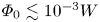
 depends on the wave normal angle distribution, but by the order of magnitude we have $\varPhi _0^*\sim 10^{-3}\;W$
 (figure 6). Since electrostatic waves reported in the Earth's bow shock have amplitudes of the order of 0.1–10 V (Hull et al. Reference Hull, Larson, Wilber, Scudder, Mozer, Russell and Bale2006; Vasko et al. Reference Vasko, Mozer, Bale and Artemyev2022), the scattering of electrons with $W\lesssim 1$
 keV can be nonlinear. We will concentrate on electron scattering below of approximately 1 keV. This is where scattering by electrostatic waves can be efficient, supplementing the scattering by high-frequency whistler waves, whose power is not sufficient for scattering $\lesssim$
 0.1 keV electrons (Amano et al. Reference Amano, Katou, Kitamura, Oka, Matsumoto, Hoshino, Saito, Yokota, Giles and Paterson2020).
Using the computed diffusion rate $D^{*}$ that is in units of rad$^{2}$
 per interaction, we estimate the pitch-angle diffusion coefficient, $D = {D^{*}}/{2\Delta t}$
 , where $\Delta t \approx L (2W/m_{e})^{-1/2}$
 is the typical time between successive electron scatterings and $L$
 is the typical spatial distance between neighbouring wave packets along the local magnetic field. Note that, below, we restore physical units for all variables. The typical spatial distance $L$
 can be evaluated using the spatially averaged electric field amplitude $E_{w}$
 of electrostatic fluctuations (Vasko et al. Reference Vasko, Krasnoselskikh, Mozer and Artemyev2018a; Shen et al. Reference Shen, Vasko, Artemyev, Malaspina, Chu, Angelopoulos and Zhang2021; Kamaletdinov et al. Reference Kamaletdinov, Vasko, Artemyev, Wang and Mozer2022)

where the amplitude $\varPhi _0$ is in units of eV, $P(\varPhi _0)$
 is the probability distribution of wave packet amplitudes, $\varPhi (\zeta )$
 is the model electrostatic potential described by Eq. (2.2), measured in units of energy (eV). Since the pitch-angle diffusion coefficient $D=D^{*}/2\Delta t$
 depends on wave amplitude it should be averaged over the probability distribution of wave packet amplitudes, $D\rightarrow \int \,\textrm {d}\varPhi _0\;P(\varPhi _0)\; D=D_0^*/2\Delta t\cdot \int \,\textrm {d}\varPhi _0\;P(\varPhi _0)\;(\varPhi _0/W)^{\nu }$
 . Taking into account that (4.1) can be written as $(eE_{w})^{\nu }=L^{-1}\int \,\textrm {d}\varPhi _0 \; P(\varPhi _0) \varPhi _0^{\nu }\int |\boldsymbol {\nabla } \phi |^\nu \,\textrm {d}\zeta$
 , where $\phi (\zeta )=\varPhi /\varPhi _0=\exp (-\zeta ^2/2l^2)\cos (k\zeta )$
 , for the averaged diffusion coefficient, we obtain

In the case of $kl\gg 1$ we have $\int |\boldsymbol {\nabla } \phi |^{\nu }\,\textrm {d}\zeta \approx k^{\nu } l\;\varGamma (1/2+\nu /2)/\varGamma (1+\nu /2) (\nu /2)^{1/2}\approx 2 k^{\nu } l/\nu$
 , where we have taken into account that $\xi ^{1/2}\varGamma (1+\xi ) /\varGamma (1/2+\xi )\approx \xi$
 for $\xi \gg 0.1$
 . Thus, the diffusion coefficient can be written in the form

clearly demonstrating that the scattering is nonlinear, because $D\propto E_{w}^{\nu }$ with $\nu <2$
 . Note that the spatially averaged amplitude $E_{w}$
 is challenging to estimate in the Earth's bow shock but we assume it to be of the order of a temporally averaged amplitude that can be easily estimated aboard spacecraft.
The diffusion coefficient (4.3) can be expressed in a form more convenient for observations

where $\varepsilon =E_{w}^2/4{\rm \pi} n_{e}T_{e}$ is the normalized intensity of electrostatic fluctuations that was previously estimated and found to be $\varepsilon \approx 10^{-6}$
 –$10^{-2}$
 for approximately ten Earth bow shock crossings (Kamaletdinov et al. Reference Kamaletdinov, Vasko, Artemyev, Wang and Mozer2022). Assuming $k\lambda _{D}=2{\rm \pi} /20$
 , $kl=9$
 , a typical plasma density of 30 cm$^{-3}$
 and an intensity of electrostatic fluctuations of $\varepsilon \approx 10^{-6}$
 –$10^{-2}$
 , we obtain the typical values of the pitch-angle diffusion coefficient of $D\sim 0.1$
 –100$\,T_e/W$
 rad $^{2}$
 s$^{-1}$
 in the case of $D_0^{*}\approx 0.4$
 and $\nu \approx 1.5$
 (figure 6(a,c) and $D\sim 0.1$
 –100$\;(T_{e}/W)^{1/2}$
 rad $^{2}$
 s$^{-1}$
 in the case of $D_0^{*}\approx 0.05$
 and $\nu \approx 1$
 (figure 6b). Above a few keV these scattering rates are well below the pitch-angle scattering rate of 100 rad$^2$
 s$^{-1}$
 reported for whistler-mode waves in the Earth's quasi-perpendicular bow show by Amano et al. (Reference Amano, Katou, Kitamura, Oka, Matsumoto, Hoshino, Saito, Yokota, Giles and Paterson2020), but below approximately 1 keV the efficiency of electron scattering by the electrostatic fluctuations can be comparable to that of whistler-mode waves. Note that electron scattering rates by whistler-mode waves and electrostatic fluctuations may strongly depend on macroscopic shock parameters, but for comparative purposes we have used the estimates obtained for whistler-mode waves in one specific Earth bow shock crossing (Amano et al. Reference Amano, Katou, Kitamura, Oka, Matsumoto, Hoshino, Saito, Yokota, Giles and Paterson2020).
In the SSDA mechanism a combination of the shock drift acceleration and pitch-angle scattering of electrons in a shock transition region allows electron acceleration from lower energies up to the maximum energy $W_{\textrm {max}}$ determined by the pitch-angle diffusion coefficient $D$
 in the plasma rest frame (Amano et al. Reference Amano, Katou, Kitamura, Oka, Matsumoto, Hoshino, Saito, Yokota, Giles and Paterson2020)

where $V_{n}$ is the upstream plasma flow velocity in the normal incidence frame, $\theta _{\textrm {Bn}}$
 is the angle between the upstream magnetic field and shock normal, $\omega _{\textrm {ci}}$
 is the upstream ion cyclotron frequency and $\eta$
 is a numerical factor of the order of one. Amano et al. (Reference Amano, Katou, Kitamura, Oka, Matsumoto, Hoshino, Saito, Yokota, Giles and Paterson2020) showed that the SSDA mechanism with pitch-angle scattering provided by whistler-mode waves can result in acceleration of electrons from thermal energies of approximately a hundred eV to a few tens of keV. In turn, our estimates show that the electrostatic fluctuations can also provide a substantial contribution to pitch-angle scattering of ${\lesssim }1$
 keV electrons in the Earth's bow shock. We can estimate the maximum energy to which electrons are accelerated through the SSDA mechanism, assuming that pitch-angle scattering is caused solely by electrostatic fluctuations. Using the diffusion coefficient given by (4.4) we resolve (4.5) with respect to the maximum energy $W_{\textrm {max}}$
 and obtain the following estimate:

where $c_{s}=(T_{e}/m_{i})^{1/2}$ is the typical ion-acoustic speed. Taking into account that, in the Earth's bow shock we typically have $\omega _{\textrm {pe}}/\omega _{\textrm {ce}}\sim 100$
 , $V_{n}/c_{s}\sim 3$
 –10, $\varepsilon \sim 10^{-6}$
 –10$^{-2}$
 and using $D_0^{*}$
 and $\nu$
 shown in figure 6 we obtain the following estimates:

where the first estimate was obtained using $D_0^{*}\approx 0.4$ and $\nu \approx 1.5$
 (figure 6a,c), while the second one was obtained using $D_0^{*}\approx 0.05$
 and $\nu \approx 1$
 (figure 6b).
Since in the Earth's bow shock $T_{e}\sim 10$ –100 eV, (4.7) show that the electrostatic fluctuations can contribute to the acceleration of thermal electrons with $W\ll T_{e}$
 up to $W_{\textrm {max}}\sim 10 T_{e}\sim 100$
 eV–1 keV. We conclude that non-adiabatic electron heating (Gedalin et al. Reference Gedalin, Golan, Vink, Ganushkina and Balikhin2023; Johlander et al. Reference Johlander, Khotyaintsev, Dimmock, Graham and Lalti2023) and increased fluxes of superthermal electrons (Gosling et al. Reference Gosling, Thomsen, Bame and Russell1989; Oka et al. Reference Oka, Terasawa, Seki, Fujimoto, Kasaba, Kojima, Shinohara, Matsui, Matsumoto and Saito2006) reported in the Earth's quasi-perpendicular bow shock can be at least partially caused by scattering due to the electrostatic fluctuations. A thorough statistical analysis of waves in the Earth's bow shock is required to quantify the contribution of different waves to electron scattering. The theoretical estimates presented here only allow us to propose that electrostatic fluctuations observed in the Earth's bow shock may cause substantial scattering of ${\lesssim }1$
 keV electrons and that they are not likely to compete with whistler-mode waves above a few keV. However, it is important to note that our theoretical estimates and discussion have been based on just a few Earth bow shock crossings considered by Amano et al. (Reference Amano, Katou, Kitamura, Oka, Matsumoto, Hoshino, Saito, Yokota, Giles and Paterson2020) and Vasko et al. (Reference Vasko, Mozer, Bale and Artemyev2022), while the properties of electrostatic fluctuations and whistler-mode waves may strongly depend on macroscopic shock parameters.
Several comments are in order about the presented estimates. First, we used a fixed ratio between electron cyclotron and plasma frequencies, $\varOmega =\omega _{\textrm {ce}}/\omega _{\textrm {pe}}=10^{-2}$ , that is, typical of the Earth's bow shock (see, e.g. Kamaletdinov et al. Reference Kamaletdinov, Vasko, Artemyev, Wang and Mozer2022). We expect this parameter to affect the diffusion coefficient, because even the quasi-liner diffusion coefficient depends on $\varOmega$
 (see equation (14) in Kamaletdinov et al. (Reference Kamaletdinov, Vasko, Artemyev, Wang and Mozer2022) obtained for electron scattering by electrostatic solitary waves). The dependence of the nonlinear diffusion coefficient $D^{*}$
 on $\varOmega$
 , where the latter parameter is typically in the range between $10^{-3}$
 and $10^{-1}$
 , needs to be quantified in the future. Second, we assumed electrostatic wave packets to have a planar wavefront or, equivalently, infinite perpendicular coherence scale. We expect a finite coherence scale to limit the efficiency of nonlinear interaction (trapping and bunching) and actually extend the applicability of quasi-linear theory to lower energies, but we leave the corresponding analysis for future studies. Third, we considered the case of wave packets with zero phase speed in the plasma frame, so that no energy diffusion occurs in that frame. In reality, the plasma frame speed of electrostatic wave packets in the Earth's bow shock is of the order of the ion-acoustic speed (figure 1), and some energy diffusion actually occurs. This energy diffusion can be directly related to the pitch-angle diffusion, since, during interaction with each wave packet, electron energy in the wave packet's frame conserves, $(V_{\|}-V_{s}/\cos \theta )^2+V_{\perp }^2=\textrm {const.}$
 , where $V_{s}$
 is the phase speed of the wave packet. Using the energy conservation condition we relate energy and pitch-angle variations, $\Delta W/W=2V_{s}\sin \alpha / (V_{s}\cos \alpha -V\cos \theta ) \Delta \alpha$
 (Lyons Reference Lyons1974; Vasko et al. Reference Vasko, Krasnoselskikh, Mozer and Artemyev2018a; Kamaletdinov et al. Reference Kamaletdinov, Vasko, Artemyev, Wang and Mozer2022). Since the speed of wave packets in the Earth's bow shock is much smaller than the speed of thermal and superthermal electrons, $V_{s}\ll V$
 , the energy diffusion can be actually neglected, $\Delta W^2/W^2\approx 4(V_{s}\sin \alpha /V\cos \theta )^{2} \Delta \alpha ^2\ll \Delta \alpha ^2$
 .
Finally, we note that the presented results may have other potential applications. First, a similar methodology can be applied to quantify electron heating and acceleration in astrophysical shocks, including those in supernova remnants and galaxy clusters, although in this case the properties of electrostatic fluctuations need to be adopted from theory or simulations. Note that Buneman and ion-acoustic fluctuations are highly likely excited in astrophysical shocks according to numerical simulations (e.g. Cargill & Papadopoulos Reference Cargill and Papadopoulos1988; Amano & Hoshino Reference Amano and Hoshino2009). Second, similar electrostatic fluctuations have been observed in other space plasma environments, including the solar wind (Gurnett & Frank Reference Gurnett and Frank1978; Mozer et al. Reference Mozer, Bonnell, Bowen, Schumm and Vasko2020), the Earth's magnetosheath (Rodriguez Reference Rodriguez1979; Mangeney et al. Reference Mangeney, Lacombe, Maksimovic, Samsonov, Cornilleau-Wehrlin, Harvey, Bosqued and Trávníček2006), the auroral region (Mozer et al. Reference Mozer, Cattell, Temerin, Torbert, von Glinski, Woldorff and Wygant1979; Temerin et al. Reference Temerin, Cattell, Lysak, Hudson, Torbert, Mozer, Sharp and Kintner1981), the inner magnetosphere (Mozer et al. Reference Mozer, Agapitov, Artemyev, Drake, Krasnoselskikh, Lejosne and Vasko2015; Vasko et al. Reference Vasko, Agapitov, Mozer, Artemyev, Krasnoselskikh and Bonnell2017) as well as reconnecting current sheets at the Earth's magnetopause and magnetotail (Graham et al. Reference Graham, Khotyaintsev, Vaivads and André2016; Liu et al. Reference Liu, Vaivads, Graham, Khotyaintsev, Fu, Johlander, André and Giles2019; Wang et al. Reference Wang, Vasko, Artemyev, Holley, Kamaletdinov, Lotekar and Mozer2022). The presented methodology can be used to quantify electron pitch-angle scattering and associated heating and acceleration in these environments.
5. Conclusions
In this paper we used the iterative mapping technique to model pitch-angle scattering of electrons by a large number of wave packets that have been observed in the Earth's bow shock. In this technique, the successive electron scatterings are not correlated, while the scattering of individual electrons can be nonlinear and occurs through phase trapping and phase bunching. The results of this study can be summarized as follows:
(i) Even though the scattering of individual electrons can be nonlinear, the long-term dynamics of electron ensembles scattered by a larger number of wave packets is diffusive.
(ii) The diffusion rate $D^{*}$
 that is in units of rad$^{2}$ per interaction depends only on the ratio between the electron energy and the wave amplitude, $D^{*}\approx D_0^{*}(\varPhi _0/W)^{\nu }$, where parameters $D_0^{*}$ and $\nu$ depend on the wave normal angle distribution of the wave packets. A quasi-linear scaling ($\nu \approx 2$) is observed for sufficiently small wave amplitudes, $\varPhi _0\lesssim 10^{-3}\;W$, while the diffusion is nonlinear ($\nu <2$) above this threshold.
(iii) The pitch-angle diffusion coefficient in units of rad$^{2}$
s$^{-1}$ corresponding to the revealed diffusion rate is given by (4.3) and (4.4). In the Earth's bow shock, the scattering of electrons below approximately 1 keV can be nonlinear and the diffusion coefficient may depend on the intensity of electrostatic fluctuations in a nonlinear fashion, $D\propto E_{w}^{\nu }$ with $\nu <2$. The typical values of the diffusion coefficient of ${\lesssim }1$ keV electrons are $D\sim 0.1$–100 $(T_{e}/W)^{\nu -1/2}\,\textrm {rad}^{2}\,\textrm {s}^{-1}$.(iv) The SSDA mechanism with pitch-angle scattering provided solely by the electrostatic fluctuations can provide acceleration of thermal electrons up to the maximum energy given by (4.7). In the Earth's quasi-perpendicular bow shock the maximum energy can be as large as approximately 1 keV.


Acknowledgements
We would like to thank MMS teams for the excellent data. All the data used in this study are publicly available at https://lasp.colorado.edu/mms/sdc/public/.
Editor A.C. Bret thanks the referees for their advice in evaluating this article.
Funding
This work of I.V. was supported by NASA grants No. 80NSSC21K0730 and 80NSSC20K1325. S.K. acknowledges support from Russian Science Foundation through grant No. 19-12-00313 covering the theoretical part of this work.
Declaration of interests
The authors report no conflict of interest.



