1. Introduction
With the rapid development of space technology, large truss structures are indispensable as important carriers of space equipment. At present, the assembly task of space trusses in space is mainly done by astronauts and auxiliary assembly tools such as robotic arms in collaboration, but there are the following problems: firstly, it is too dependent on human power, while human beings assemble trusses in space with spatial limitations and dangers in operation [Reference Jiang, Cao, Huang, Li and Ceccarelli1], and in the future, there will be a variety of condition constraints such as a larger scale of the work object and more tasks; secondly, the existing space robots have a fixed structure and single function, and do not have the universality of multi-scene work. To address the above problems, it is necessary to design a reconfigurable cellular robot with rich functions and flexible motion. The earliest cellular robots can be derived from the concept of CEBOT [Reference Fukuda, Buss and Kawauchi2] proposed by Fukuda et al. in 1989, and with the rise of the concept of CellSat [Reference Tanaka, Yamamoto, Yairi and Machida3], cellular robots have become a hotspot of research in recent years. Cellular robots are a kind of robot that can be reconfigured into multiple configurations according to the requirements of space missions [Reference Zhang, Ye, Ji, Wu, Zhu and Wang4], which consist of multiple cellular modules with multi-level structures such as organs, tissues, and cells, and is a kind of modular robot. Valsamos et al. [Reference Valsamos, Moulianitis and Aspragathos5] presented a method for the kinematic synthesis of structure topologies for modular metamorphic serial manipulators, and the metamorphic structure representation is proposed for the systematic representation of this type of metamorphic manipulator structures. Modular self-configurable robot systems, often referred to as a swarm robot system, and their applications have been widely explored to meet emerging automation needs in various applications, such as space exploration, manufacturing, defense, medical industry, entertainment, and services [Reference Vu, Bi, Mueller and Younis6]. Through multi-level reconfiguration and deconstruction, cellular robots have more flexible and diverse configurations to adapt to more complex environments, and their functions are enriched due to the diversity of their configurations, so they have a wide range of application areas and can adapt to the trend of complexity and diversity of future space missions [Reference Bing and Zhen7, Reference Dai, Li, Chen, Nie, Rui and Zhang8].
In terms of cellular robot structure, many scholars have done related research. Sankhar et al. [Reference Reddy, Abhimanyu, Tejas and Tejas9] designed a modular bionic robot, 2DxoPod, which features a combination of modularity and bionic benefits that can allow it to remain highly maneuverable in complex environments. The core design of the robot structure is a novel articulated mechanism that provides two mutually orthogonal degrees of freedom in the same position. The modular design improves the robot’s locomotion flexibility, multiple modules can be combined following the joint structure of vertebrates, and the bionic structure helps to improve the robot’s locomotion coordination. However, the machine has not yet been practically applied, and a control model needs to be designed to control the robot’s motion, and further testing of the robot’s motion performance is required. Liu et al. [Reference Liu, You, Wang, Wen, An and Wen10] designed a new type of variable topology cellular space robots (CSRs) with a variety of units with different functions. Its connecting cells can be connected by changing the distribution of connecting interfaces to form a variety of different connecting functions, which improves the topological connectivity of the CSR. The CSR can form a five-degree-of-freedom robot configuration, and the workspace of the robot can be varied by changing the number of rod-length cells. Valsamos et al. [Reference Valsamos, Moulianitis and Aspragathos11] introduce an approach for the determination of the best anatomy of a metamorphic manipulator for a given task at a given location. The location of the task is determined by maximizing the performance of a current industrial fixed anatomy robot. The proposed approach is tested and the results show that the determined best anatomy for each type of task acquired higher performance than the respective one achieved by the fixed anatomy manipulator.
Path planning is one of the key technologies for mobile robots, and with the rapid development of robotics, more and more people are researching path planning algorithms [Reference Y-q, J-l, Yang, Z-q and H-l12–Reference Gao, Shen, Guan, Zheng and Zhang16], and there is an urgent need to solve the path planning problem in complex environments. Xu et al. [Reference Xu, He, Tian and Wei17] proposed a Gaussian Random Paths Motion Planner (GRPMP) for solving the robot motion planning problem. Compared with traditional sampling-based methods, GRPMP uses a random path sampler based on a Gaussian process to generate a set of smooth random paths discretized into sparse nodes, which reduces the resource space occupation and improves the success rate of planning. Yan et al. [Reference Yan, Zhou and Luo18] proposed a secure heuristic path-planning method based on a search strategy. The method can be combined with environmental facilities to obtain the optimal path between the starting point, the optimal boundary point, and the endpoint. Compared with the traditional A-star algorithm, the method provides significant improvements in terms of path length, execution time, and path smoothness. Zhao et al. [Reference Zhao, Cai, Wang and Li19] proposed a Golden Sine Grey Wolf Optimizer (GSGWO) adapted to over-barrier functions, which is improved from the Grey Wolf Optimizer (GWO). In path planning experiments, GSGWO plans better path lengths, number of inflection points, inflection point sizes, and path stability than GWO. Tian et al. [Reference Tian, Liang, Wei, Luo and Zhou20] proposed a hybrid Firefly-Whale Optimization Algorithm based on multiple swarms and inverse learning using Whale Optimization Algorithm and Firefly Algorithm. The algorithm can quickly find optimal paths in complex mobile robot working environments and can achieve a balance between exploitation and exploration. Aiming at the problem of unreachable obstacles near the target in an artificial potential field, Gu et al. [Reference Gu, Liu, Wang, Yu and Guo21] proposed an adaptive and safe path planning method, which introduces a smooth decay function in the repulsive potential field. In terms of escaping local minima and reducing energy consumption, the performance of this method is improved compared to existing APFs. Gao et al. [Reference Gao, Li, Liu, Ge and Song22] deal with the path-planning algorithm for continuum robots in confined multi-obstacle environments to prevent their over-deformation, and a path-planning algorithm called the continuum-RRT* algorithm herein is proposed to achieve fewer iterations and faster convergence as well as generating desired paths that adhere to the kinematic limitations of the continuum robots. Zhan et al. [Reference Zhan, Chen, Chen and Zhang23] investigated the problem of achieving balanced multi-UAV path planning for persistent monitoring tasks, proposing two new metrics, waiting factor and difficulty level. For a single UAV, the ant colony initialized genetic algorithm has been proposed to plan its path and obtain its difficulty level. For multiple UAVs, the K-means clustering algorithm has been improved based on difficulty levels to achieve balanced task allocation.
Many scholars have done research in the related field of A-star algorithm. Chen et al. [Reference Chen, Li, Yuan and Gu24] proposed an improved A-star algorithm, for the defects of the A-star algorithm which is time-consuming, introducing the vector angle cosine value to improve the evaluation function, reducing the number of useless nodes, and making the selection of extended nodes more directional; adding the cosine function to the value function effectively limits the range of search nodes, improves the search time efficiency of the A-star algorithm, and generates the best path. Chen et al. [Reference Chen, Tan, Mo, Wang, Wu and Zhao25] added the artificial potential field method in the search evaluation of the A-star algorithm, which makes the ability of the A-star algorithm to avoid obstacles has been greatly improved. Duan et al. [Reference Duan, Wu and Liu26] proposed an improved A-star algorithm that optimizes the path nodes of the search by introducing the Bresenham straight-line algorithm. The improved A-star algorithm improves the path smoothness and reduces the number of turns and the optimal path is shorter. Zhan et al. [Reference Zhan and Huang27] combined the Dynamic Window Approach with the A-star algorithm, and the final path obtained was more coherent with the robot’s running path. Liao et al. [Reference Liao, Chen, Wu, Zeng, Ouyang and Guan28] proposed a path-planning method that combines the adaptive A-star algorithm with the improved Dynamic Window Approach.
In summary, both cellular robot structure and robot path planning are hot and difficult in robotics research, and many research directions can be expanded in the future. Many researchers have studied these two aspects, but seldom combine them together. In this paper, we optimize and innovate these two aspects and combine them to design a cellular robot suitable for space trusses to take advantage of modular robots, and use the improved Lifelong Planning A-star (LPA-Star) algorithm to solve the path planning problem of the robot in space trusses so that it can avoid dynamic obstacles. The path planning strategy studied in this paper can provide a solution to the dynamic path planning problem with multiple nodes in 3D space. The study of cellular robot structure as well as path planning has both positive theoretical significance and important practical significance for future space exploration.
2. Structural design of cellular robots in space
2.1. Structural design of multifunctional cell modules
Firstly, the cellular robots are composed of several multifunctional cellular modules connected by connecting surfaces, so the multifunctional cellular modules must have docking function; secondly, the cellular robots need to carry out self-reconfiguration to form a variety of configurations, which requires the cellular modules to move autonomously; and lastly, the cellular robot needs to move to accomplish multiple work tasks on the truss and must have a certain degree of freedom, so the multifunctional cellular module needs to have a rotary function so that the robot joints can rotate. Most of the cellular robots designed by many scholars before are only equipped with the above single or partial functions, and then the working functions of cellular robots are realized by combining different kinds of cellular robots, whereas the innovation and special feature of cellular robots in this design is to realize the above multiple functions on one kind of cellular robots.
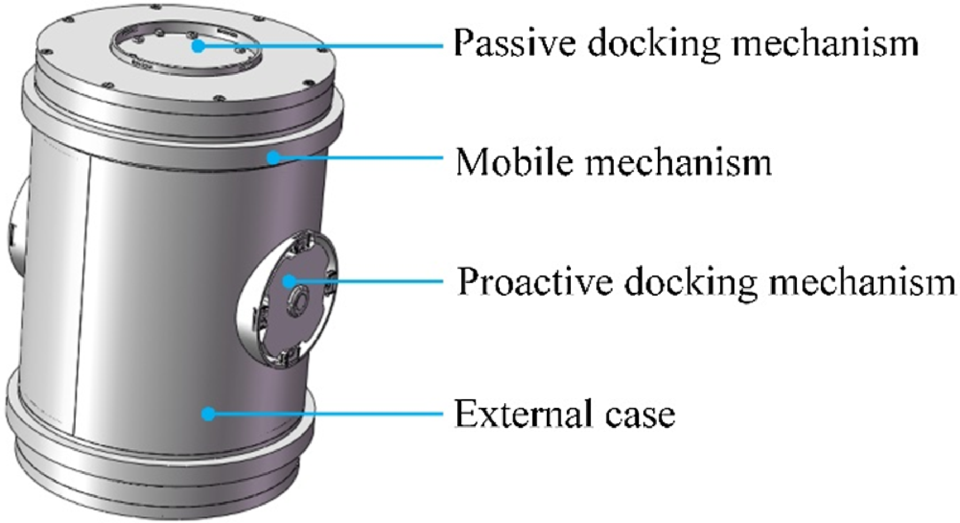
This paper mainly designs a multifunctional cell module that combines three functions into one, and the realization of its functions relies on a set of overall mechanical structures, the shape of which is shown in Figure 1. The cell module as a whole is a cylinder with a bottom diameter of 200 mm and a height of 300 mm, the docking mechanism mainly consists of two connecting surfaces on the top and bottom of the cylinder and two connecting surfaces on the left and right sides of the cylinder, and the connecting surfaces are divided into active connecting surfaces and passive connecting surfaces; the mobile mechanism is a protruding two-wheeled structure, and the two-wheeled structures can be driven to move in multiple directions on the reconstruction platform; the rotating mechanism is inside the cell module, and can drive the passive connecting surfaces to realize 360° rotation.
External structure of multifunctional cell module.

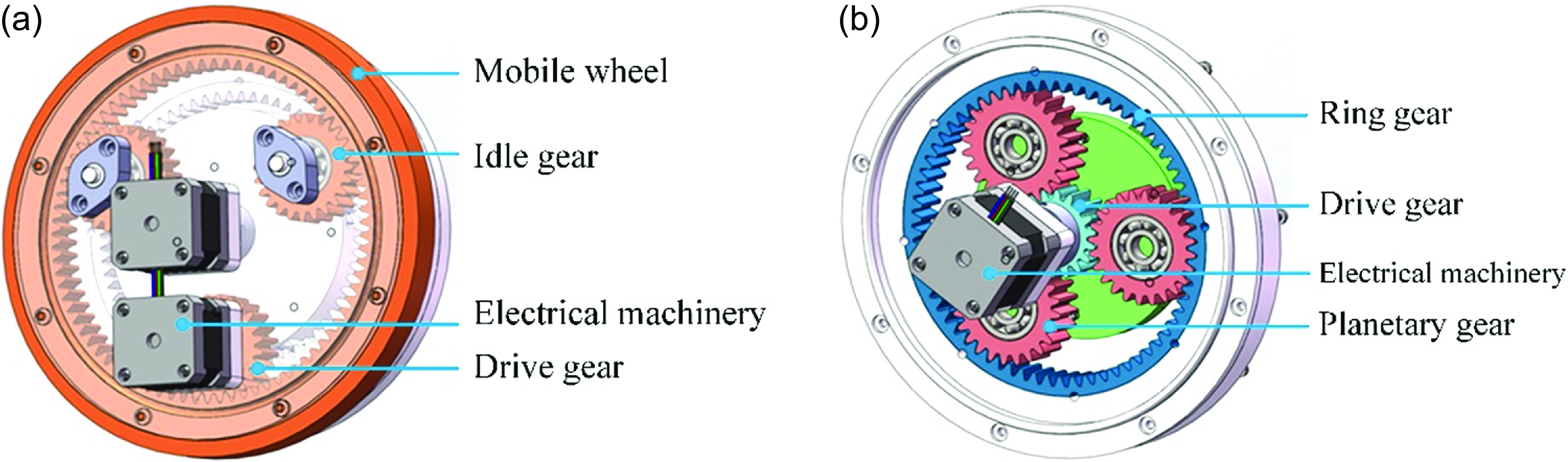
The multifunctional cell module has a mobile mechanism and a rotary mechanism, as shown in Figure 2. The mobile mechanism is shown in Figure 2 (a), including an electrical machinery, a driving gear, a mobile wheel, and two idler gears which are the same as the driving gear. The electrical machinery drives the driving gear to rotate, and the driving gear drives the mobile wheel to rotate, and the idler gears can reduce the loads brought about by the movement of the mobile wheel, so as to make the force of the wheel system more reasonable. The two mobile wheels of the multifunctional cell module rotate at the same speed and direction, it can realize forward or backward; if the rotating direction is the same and the speed is different, it can realize the turning movement; if the rotating direction is opposite, it can realize the in-situ rotating movement of the cell module. The ingenuity and innovation of this design lie in the fact that through a simple transmission structure, a variety of movement forms of the cell module itself can be realized, including forward, backward, turning, and in-situ rotation, and these movement forms can fully satisfy the mobile function of the multifunctional cell module. The rotary mechanism is shown in Figure 2 (b), which includes an electrical machinery, a driving gear, three identical planetary gears, and a ring gear. The middle driving gear is driven by the electrical machinery, and then the power is transmitted through the planetary gears, and the ring gear outputs the power to start rotating. The ring gear is connected to the passive connecting mechanism, not connected to the frame, which can drive the passive connecting surface to rotate 360°, and the cell module itself does not move, which can meet the needs of module docking, and can also act as the rotary joint of the robot after docking is completed. This design can realize the precise control of the rotation angle and precision and has the characteristics of simple and practical, transmission and high efficiency.
Mobile mechanism and rotary mechanism. (a) Mobile mechanism. (b) Rotary mechanism.

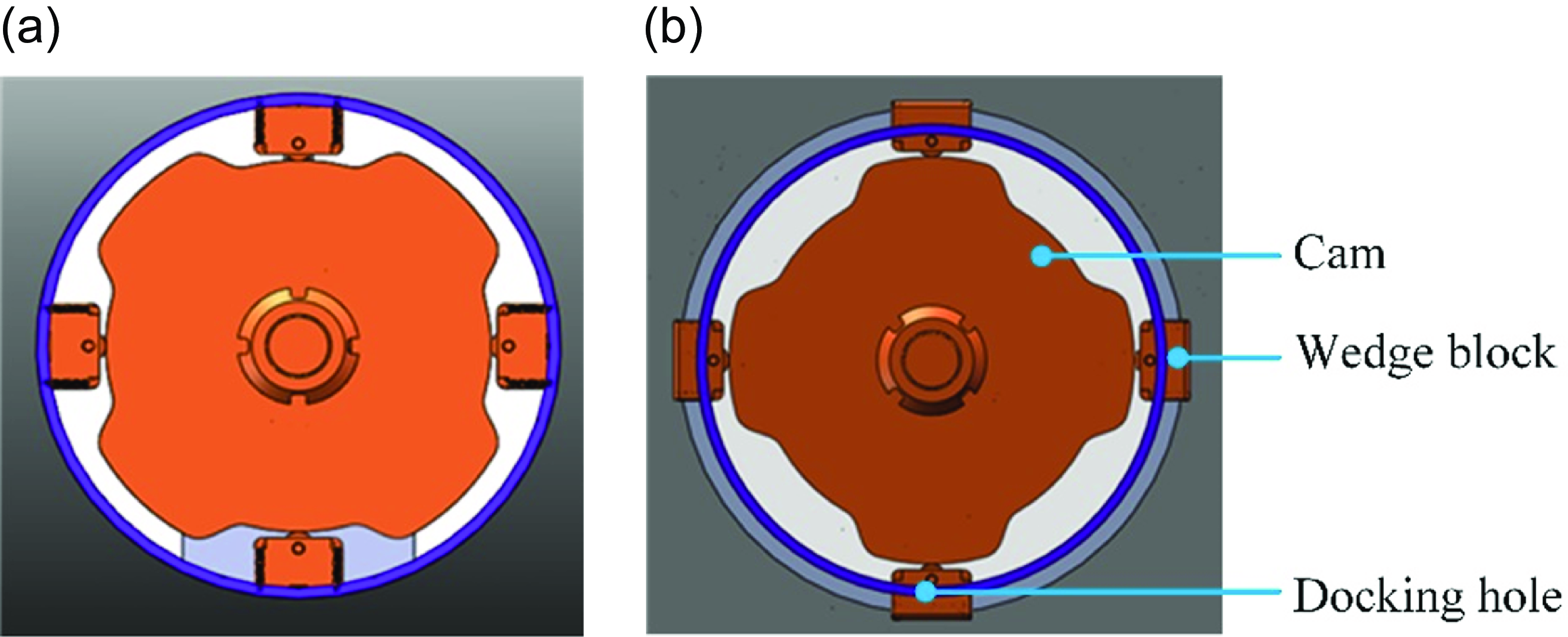
The docking function of the multifunctional cell module is accomplished through the connection of the active docking mechanism and the passive docking mechanism, and the docking process of this design adopts an ingenious wedge block snap device. The two states of the active docking mechanism are shown in Figure 3, with the left side being the state before the docking starts and the right side being the state after the docking is finished. The active docking mechanism mainly consists of a cam, four wedge blocks, springs connected to the wedge blocks, and four docking holes. Before docking starts, the wedge blocks are pushed against the concave surface of the cam due to the action of the spring, and do not expose the docking holes. When docking starts, the active connecting surface is embedded inside the passive connecting surface, and the docking holes on the two connecting surfaces are aligned by the rotary mechanism, and the electrical machinery in the active docking mechanism drives the cam to rotate, and the wedge blocks are gradually pushed out by the cam surface and passes through the docking holes, which locks the two connecting surfaces in a relative position until the wedge block is completely pushed out by the most convex point, the electrical machinery stops rotating and realizes self-locking, which realizes precise docking of the active connecting surface and the passive connecting surface. The mechanical structure of this docking mechanism is ingenious and simple, the rotary motion of the cam mechanism is converted into the linear motion of the wedge block by the roller and spring, and the design of the four docking holes can make the docking structure more solid and stable. The docking mechanism is integrated into the multifunctional cell module, realizing the effective combination of the docking function and the cell module, and reasonably utilizing the internal space of the cell module without affecting the other functions of the cell module.
Two states of active docking mechanism. (a) Pre-docking state. (b) Docked state.

2.2. End-effector structural design
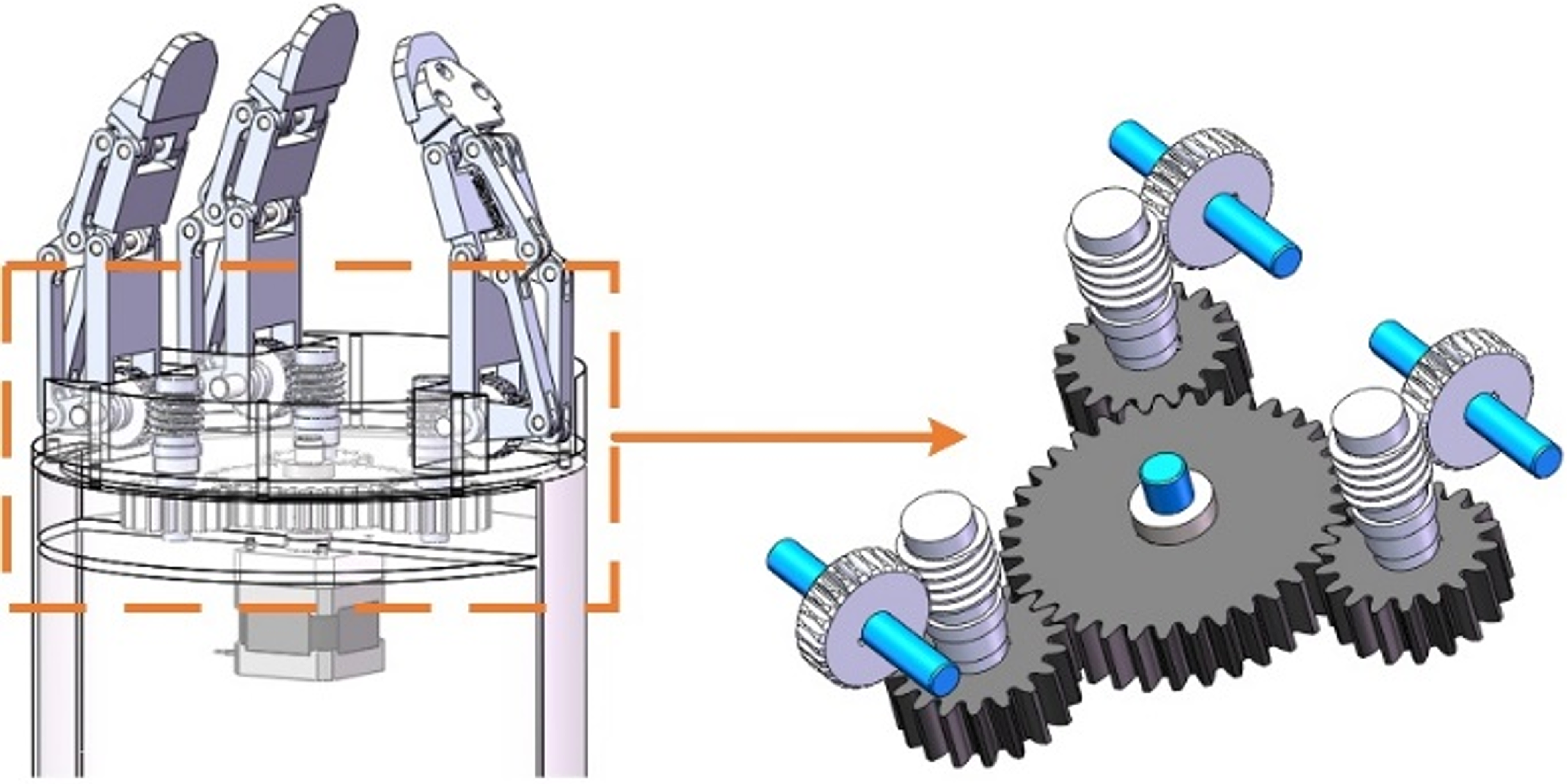
The end-effector is the actuator of the cellular robot, which is used for work tasks such as gripping trusses, and it also has the same internal docking mechanism as the robot module mentioned above, so that it can be docked with the robot module. The internal structure of the end-effector is shown in Figure 4, which adopts an adaptive gripping jaw and is mainly composed of three mechanical knuckles and a transmission mechanism. The motor can drive the sun wheel to rotate, then transmit the power to the worm gear through the three planetary wheels, and finally change the rotating direction through the worm gear to drive the three knuckles to realize the action of tensioning and clamping, and this underdriven gripping jaws design can make the gripping jaws adaptive, and it can grasp various complex shapes of trusses.
End-effector internal structure.

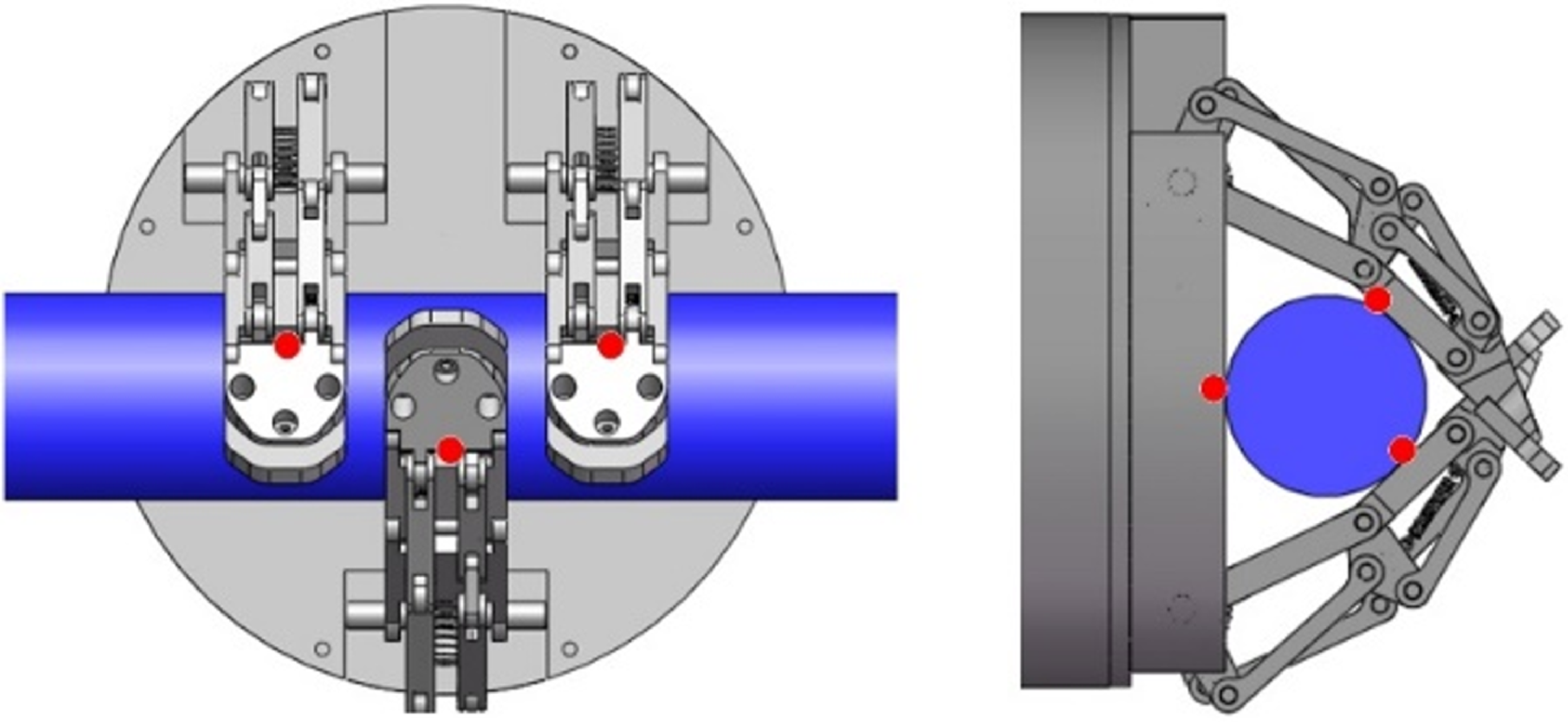
In the process of gripping the truss round bar, the end-effector jaws can be tightened slowly, and finally, one end of the truss round bar is tangent to the three knuckles, and the other end is tangent to the module shell, and the red markings in Figure 5 are the contact positions of the jaws when clamping the truss round bar. Compared with the clamping jaw with two knuckles, this kind of clamping jaw has more contact points with the truss, there are four tangent contact positions, and the contact positions are reasonably distributed, so that it can be more stable when clamping the truss. Adopting servo motor to provide power source for the mechanical gripper is more conducive to realizing the digital control of the motor and then controlling the clamping strength of the gripper.
Gripping state of the jaw.

2.3. Cellular robot configuration program design
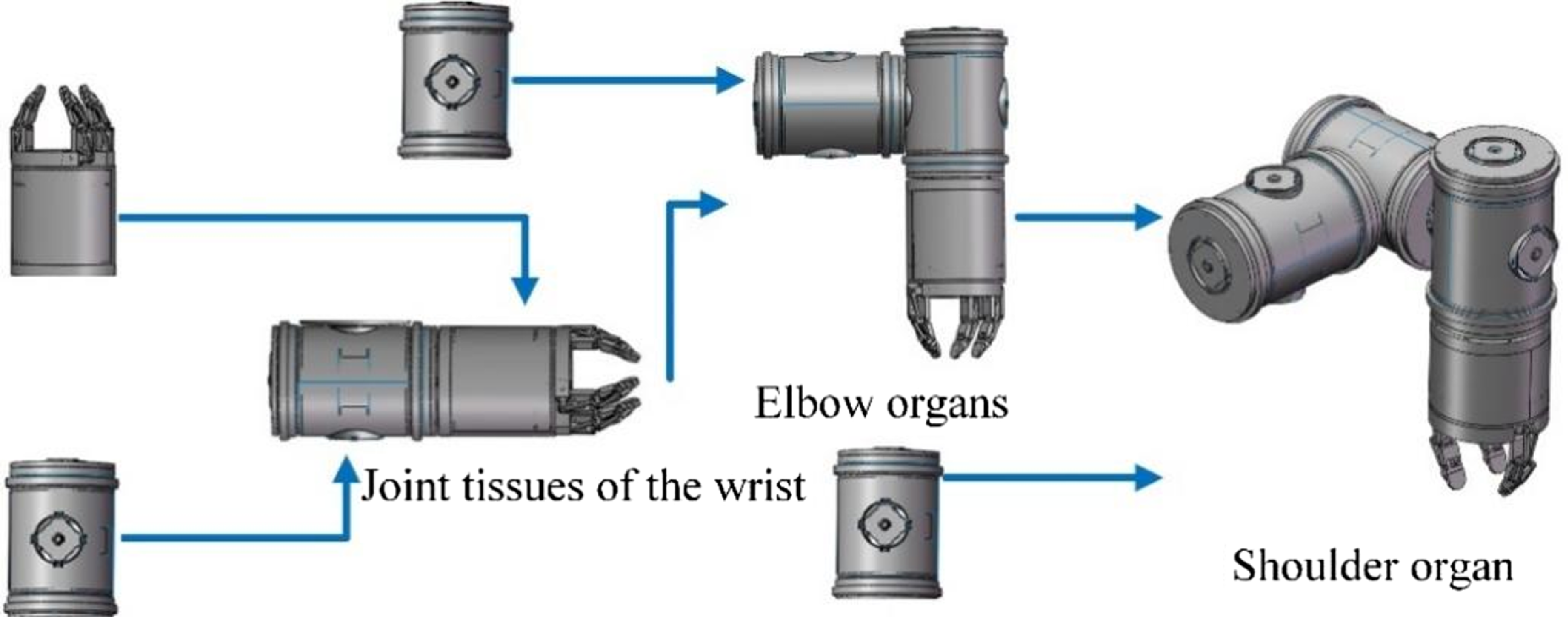
The cellular robot is based on a multifunctional cellular module as the basic unit, and the degrees of freedom required for the overall robot motion are mainly provided by rotation between modules. In order to ensure the diversity and flexibility of robot movement, there should be at least two mechanical grippers with six degrees of freedom. As shown in Figure 6, which is a schematic diagram of the combination process of the shoulder organ, the shoulder organ will be able to fully meet the working requirements of one mechanical gripper jaw.
Schematic diagram of the process of combining the organs of the shoulder.

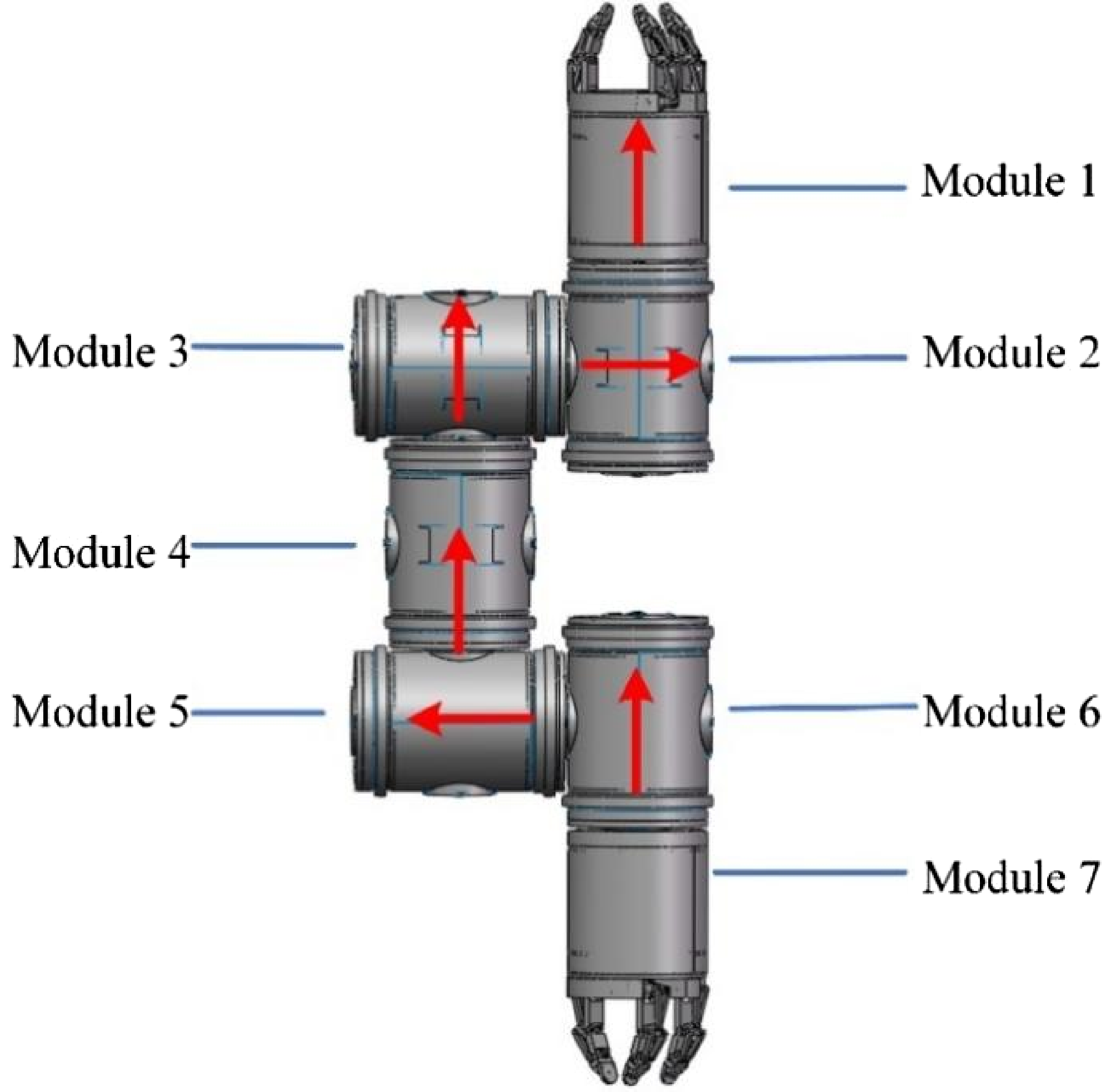
The above shoulder organs have three rotational degrees of freedom, which can only satisfy the motion requirements of one gripper claw. Combining the two shoulder organs will enable the cellular robots to fulfill the space truss assembly task. The basic anatomy of the cellular robot is shown in Figure 7, which includes a total of seven multifunctional cellular modules. Among them, module 4 adopts two multifunctional cellular modules with passive connecting surfaces on the bottom, and the rest of the modules adopt multifunctional cellular modules with one active connecting surface and one passive connecting surface on the bottom, and the joints of each module can be rotated by 360°, and the rotation axes are shown by the red arrows in the figures. This robot’s anatomy fully meets the design requirements and has many advantages such as simple structure, diverse positions, easy reconfiguration, and suitable size, which can finally be identified as the cellular robot used in this paper.
Basic anatomy of a cellular robot.

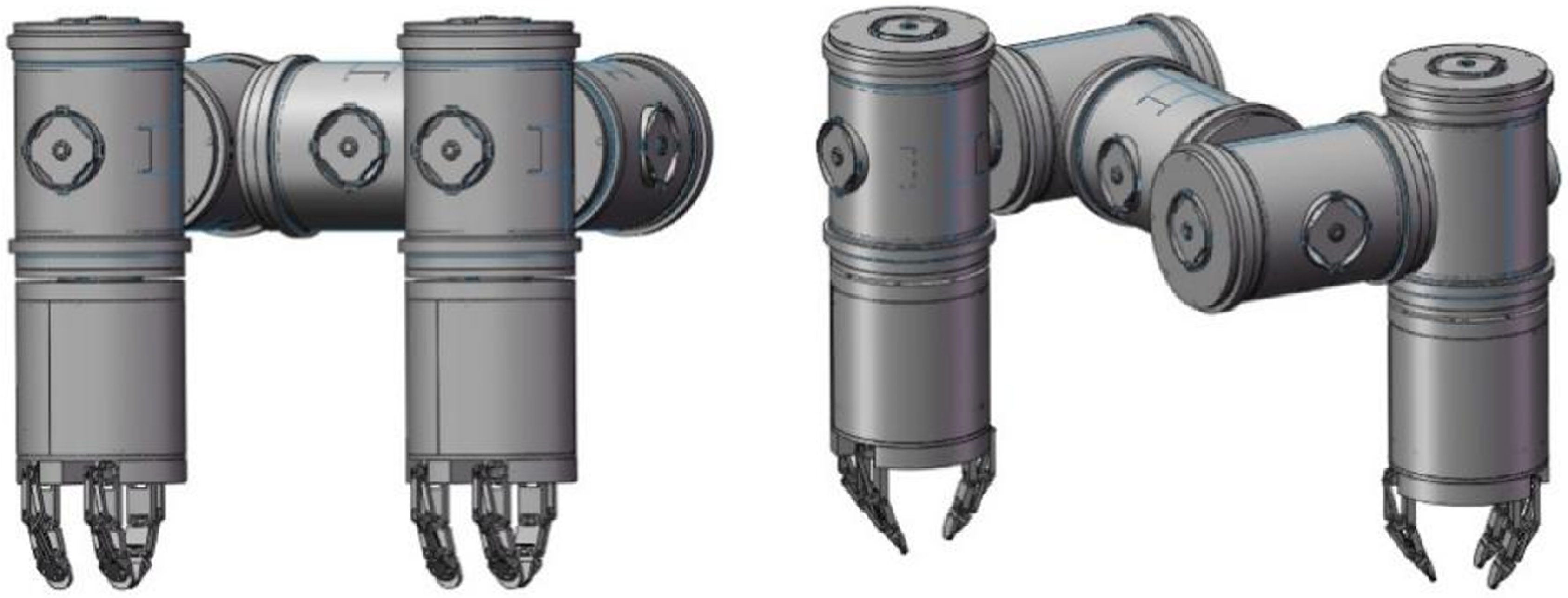
Under the basic configuration of this robot, the posture can be changed to adapt to different work tasks. As shown in Figure 8, after the joint rotation transformation, two robot postures can be formed, which can be selected according to different truss environments and move with different gaits, with more flexible transformation ability and stronger obstacle-crossing ability.
Two robot postures.

3. Improved A-star and LPA-star algorithms
The more common path-planning algorithms can be roughly categorized into geometric model algorithms, intelligent search algorithms, local planning algorithms, artificial intelligence algorithms, and other hybrid algorithms. The model used in this paper is a three-dimensional truss model, which can be simplified as a mathematical model composed of nodes and connecting line segments, and the path planning on the truss can be regarded as the optimal path planning between the two nodes, so this paper chooses the geometric model algorithm. In the geometric model algorithm, A-star algorithm has the advantages of more efficient search speed and better optimization effect [Reference Tang, Tang, Claramunt, Hu and Zhou29], but if the obstacle position changes in the process of path planning, that is, dynamic path planning, A-star algorithm will not be able to deal with it; LPA-star can solve the dynamic path planning problem, but the algorithm is less applied, and there are some problems in the process of application. The robot can’t predict and avoid obstacles in advance, for example, if the obstacle happens to be in the same position as the robot when it appears, the robot will collide with the obstacle. Therefore, this paper will improve the design of these two algorithms so that they can better solve the dynamic path planning problem.
3.1. Introduction to the improved A-star algorithm
A-star algorithm is a commonly used path planning algorithm to search for the shortest path between two points with the help of the heuristic function, by introducing the concept of “traveling cost,” in the process of each round of the cycle, it only selects the node with the lowest “traveling cost.” By introducing the concept of “traveling cost,” in each round of the cycle, only the node with the lowest “traveling cost” is selected for exploration, and the traveling cost is related to the position of the target point, so that the A-star algorithm has a certain direction when exploring the nodes, and can explore the target node as soon as possible under the condition of exploring fewer nodes, which greatly improves the efficiency of the search. The cost function is shown in Eq. (1):
 \begin{equation} f\left(n\right)=g\left(n\right)+h\left(n\right) \end{equation}
Where: f(n) represents the current total cost of node n, g(n) represents the current cost of moving from the starting point to the current node, and h(n) represents the predicted cost of reaching the goal point from the current point, which is also the heuristic function.
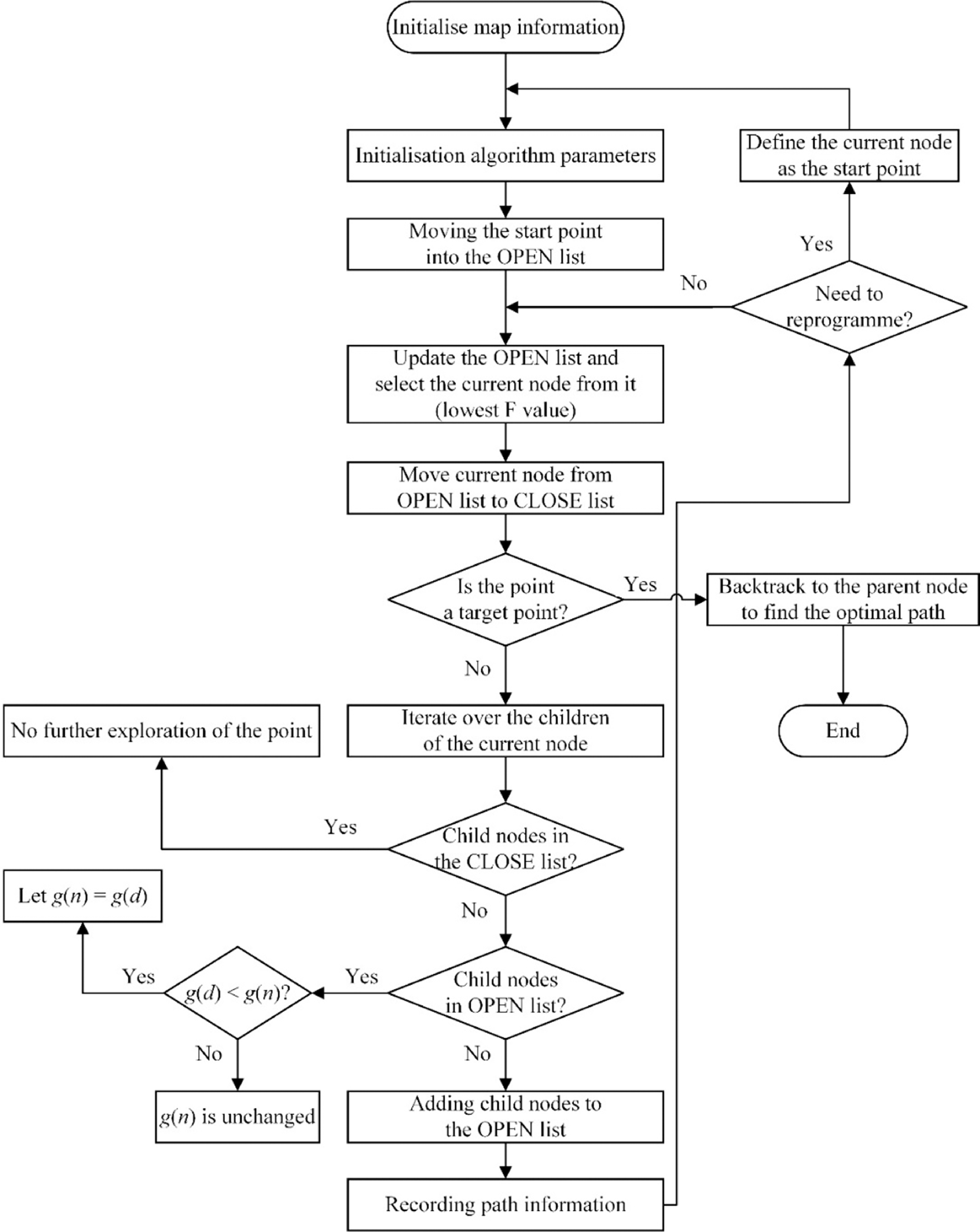
The traditional A-star algorithm can only complete the global path planning at one time and then execute it, which is only applicable to the situation where the position of the obstacle does not change, and cannot solve the path planning problem of dynamic obstacles, this paper adds the re-planning part of the path on the basis of the traditional A-star algorithm. The improved A-star algorithm executes according to the path planning, if the current exploration point encounters or is about to encounter a dynamic obstacle, it will re-route the path planning at the current location, and this re-routed path is obtained by searching according to the changed map, which can bypass the obstacle, and it is the optimal path from the current point to the target point. The improved A-star algorithm can solve the dynamic path planning problem of the 3D truss.
The improved A-star path planning algorithm is shown in Figure 9:
Flow chart of improved A-star algorithm path planning.

3.2. Introduction to the improved LPA-star algorithm
The LPA-star algorithm is an incremental heuristic search lifetime planning algorithm that can be used for the shortest path problem from a given start point to a given goal point in dynamic environments. LPA-star algorithm, as an incremental version of A-star, has the advantages of an incremental algorithm in addition to those of a heuristic algorithm. When the searched map (e.g., the location of obstacles) is changed, the algorithm can reuse the previously searched path information, change only the search node information related to the obstacles, and continue to plan the optimal path after the map is changed on this basis. This incremental search can effectively utilize the previous search information and does not need to recalculate the information of the whole map from the starting point, which can effectively improve search efficiency [Reference Koenig, Likhachev and Furcy30].
To better describe the LPA-star algorithm, the important parameters of the algorithm are described:
S: represents the set of nodes in the map;
c(s 1 , s): represents the cost function from node s 1 to node s;
g(s): represents the expected shortest distance from the starting point to the current node s. When g(s) = rhs(s) for all nodes, the value of g(s) is the actual shortest distance from the starting point to the current node;
rhs(s): the current minimum generation value of node S, i.e., for all neighboring nodes of S, find the minimum g-value among them, and then add the generation value of the neighboring nodes arriving at the node of S, which can be expressed in Eq. 2;
 \begin{equation} rhs\left(s\right)=\left\{\begin{array}{l} 0\\ \min \left(g\left(s_{1}\right)+c\left(s_{1},s\right)\right) \end{array}\right.\begin{array}{l} \text{if }s=s_{0}\\ \text{otherwise} \end{array} \end{equation}
Where: s 0 represents the starting point and s 1 represents all the neighboring nodes of s.
If g(s) >rhs(s), it is a local over-consistent state; if g(s) ≤ rhs(s), it is a local under-consistent or local consistent state;
U: represents the priority queue of the LPA-star algorithm, when a node becomes locally inconsistent, it will be placed in a priority queue for reevaluation, which is equivalent to the to-be-explored list in the previous section, the difference is that this queue is sorted based on the k 1 and k 2 values of each node, and is selected according to the order of k1 followed by k 2 , and the smallest node of the k-value is preferred to explore when it is being explored, and the k(s) is specifically The value of k(s) is shown in Eq. 3:
 \begin{equation} k\left(s\right)=\left[\begin{array}{l} k_{1}\left(s\right)\\ k_{2}\left(s\right) \end{array}\right]=\left[\begin{array}{l} \min \left(g\left(s\right)\!,rhs\left(s\right)\right)+h\left(s,goal\right)\\ \min \left(g\left(s\right)\!,rhs\left(s\right)\right) \end{array}\right] \end{equation}
Where: h(s, goal) is the predicted cost from the current node to the goal point.
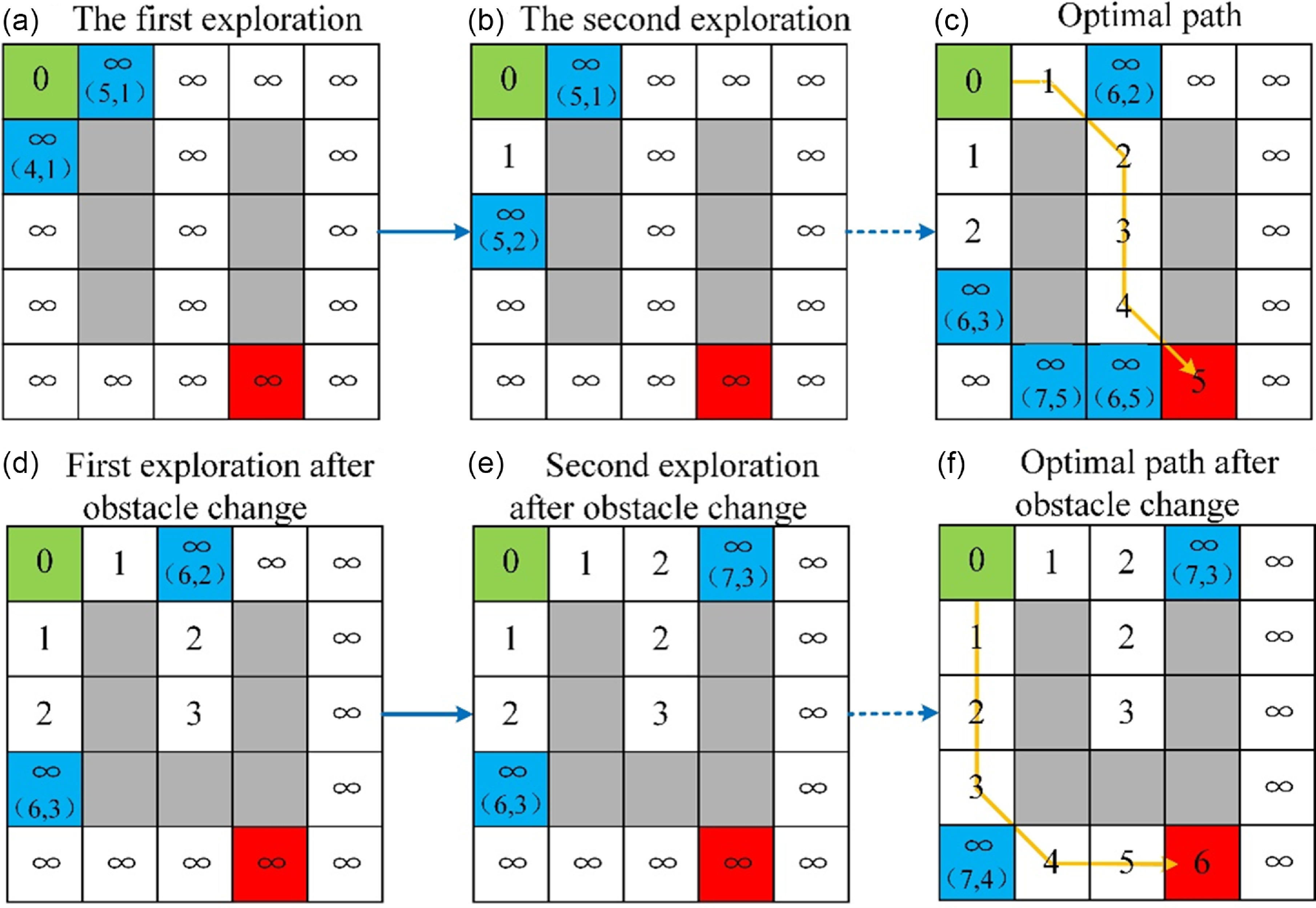
To facilitate the understanding of the basic principle of the LPA-star algorithm, it is illustrated in the form of a square map, as shown in Figure 10, which is an example diagram of the principle of the LPA-star algorithm. The green square is the start point, the blue square is the point in the priority queue, the gray square is the obstacle, the red square is the target point, and the numbers in parentheses are (k 1 , k 2 ). After the initialization of the algorithm, the starting point rhs = 0<g=inf (infinity), move it into the priority queue, make g = rhs = 0, move the starting point out of the priority queue, start traversing the neighboring nodes of the starting point, and calculate their rhs values, judge them to be in the state of local over-consistency, and therefore add them into the priority queue as shown in Figure 10 (a); and then find the point with the existence of the smallest k-value as the starting point node below, the same judgement that the node is in a local over-consistent state, so that g = rhs = 1, the subsequent repetition of the above process, as shown in Figure 10 (b); omit similar processes in the middle, and ultimately get an optimal path, as shown in Figure 10 (c); when the location of the obstacle changes, there is one more obstacle, which is unaffected by the obstacle’s parent node, the neighboring child node rhs = inf, the information of other nodes does not change, as shown in Figure 10 (d); therefore LPA-star can continue to follow the above process to find the path, and finally find a new path, as shown in Figure 10 (f).
Example diagram of Lifelong Planning A-star algorithm principle.

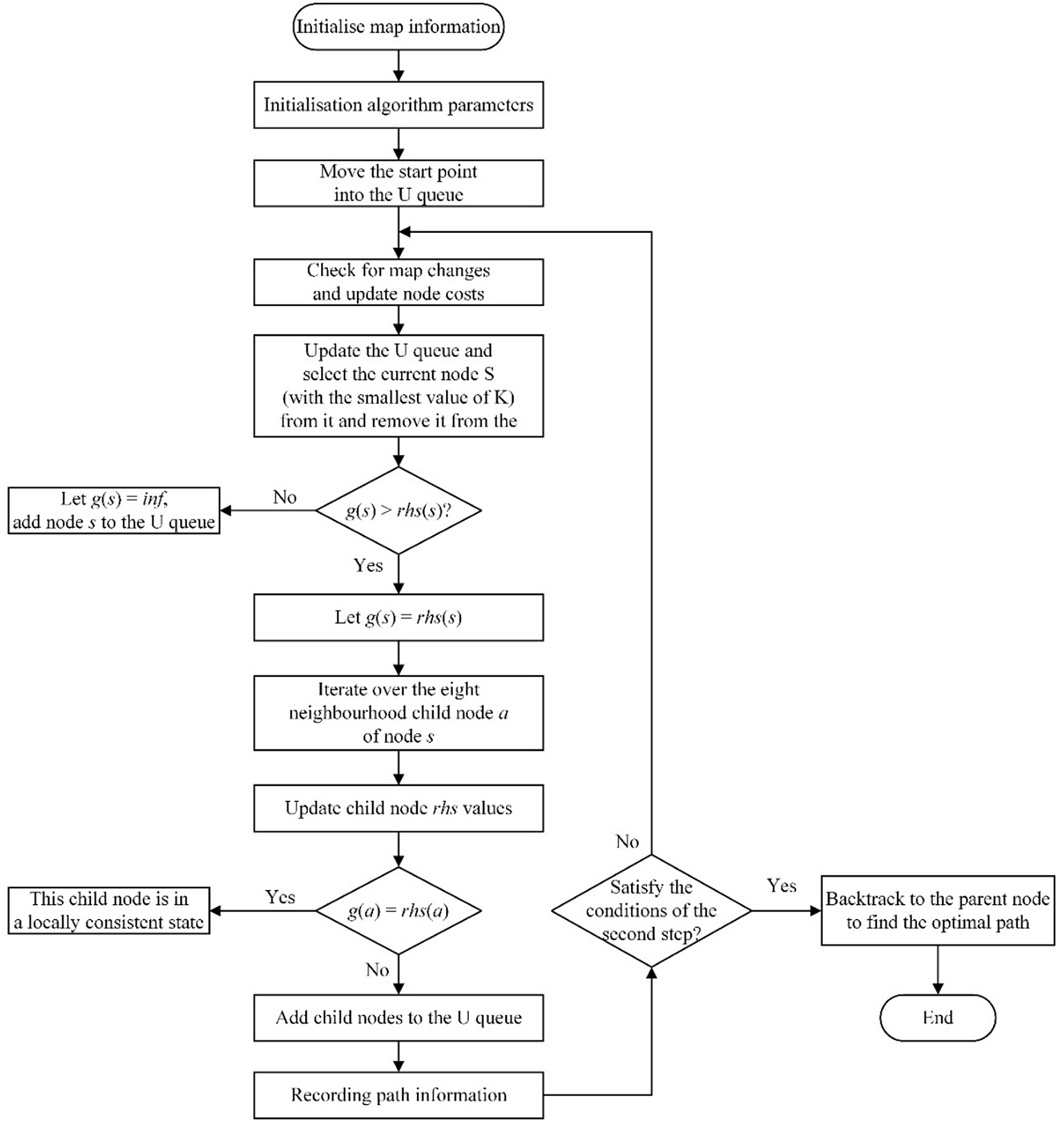
The LPA-star algorithm executes only one step at a time during path planning, after which it checks whether the map has changed, and if it affects the traveling path then the path is re-planned, and if it does not then the next step is executed. The advantages of the LPA-star algorithm are that it can solve the dynamic path planning problem, and it can make use of the previous information, which can greatly improve the search efficiency. However, the traditional LPA-star algorithm will have a problem in that at the current moment, the robot’s position happens to be the position where the obstacle appears, then the robot needs to fold back, which will take two more steps to improve the optimal path value, which is not conducive to the robot’s path planning, so in this paper this part of the algorithm to improve the design. The improved LPA-star algorithm detects the current moment together with the obstacle information of the next moment, and updates it in the algorithm, so that the robot and the obstacle can avoid arriving at the same position, and the robot can avoid the obstacle in advance, which greatly improves the efficiency of the path planning, and also ensures the safety of the robot’s moving process from the perspective of the practical application.
Flow chart of improved Lifelong Planning A-star algorithm path planning.

The improved LPA-star path planning algorithm is shown in Figure 11:
4. Two improved algorithms for truss path planning
4.1 Three-dimensional truss mathematical model construction
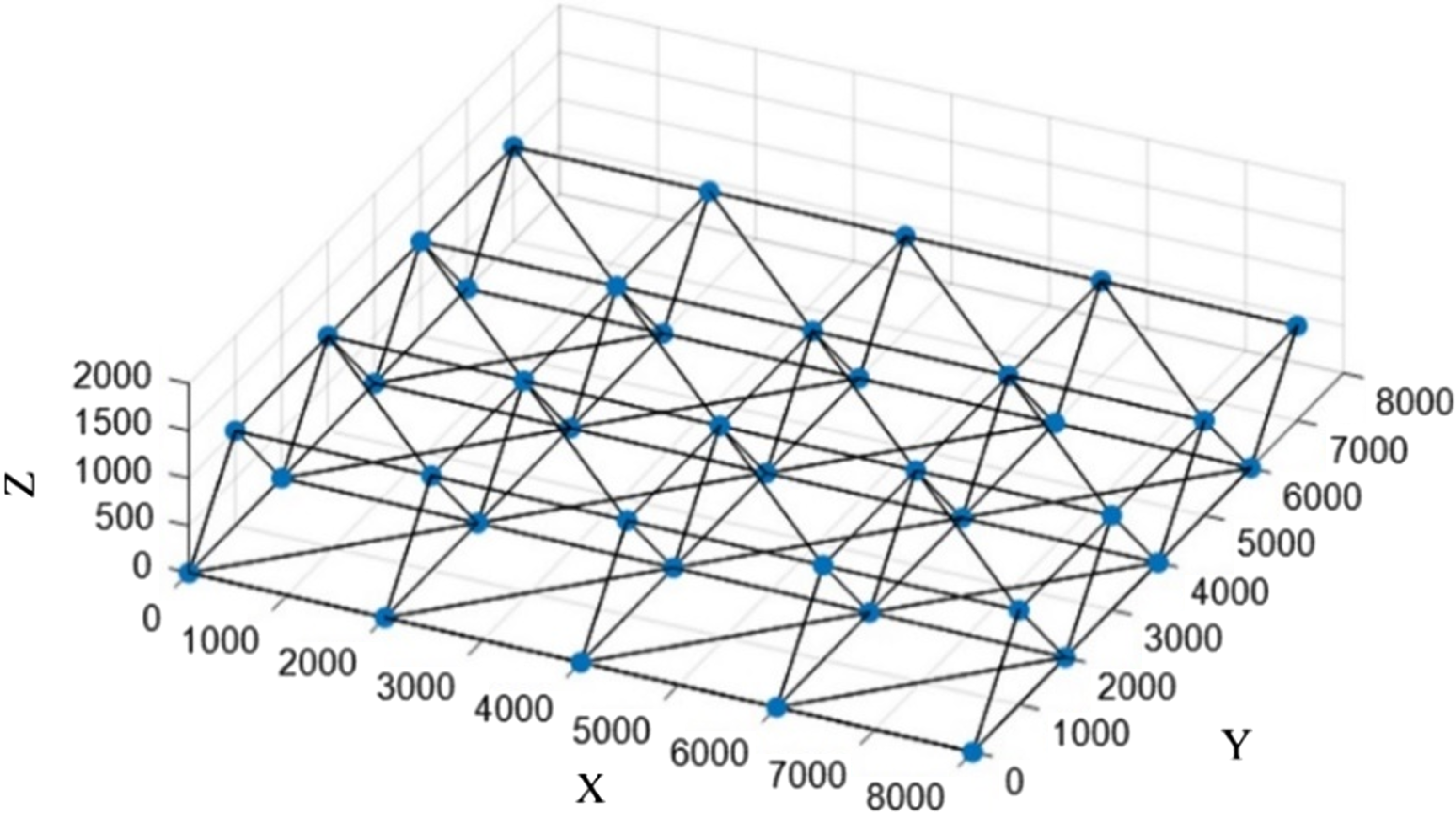
The spatial truss mathematical model used in this paper is shown in Figure 12, 40 geometric centers of the truss joints are taken as the path nodes, and a 40 × 3 matrix is established in MATLAB, the truss nodes can be divided into upper and lower layers, the bottom nodes are No. 1-20, and the upper nodes are No. 21-40, the length of the truss is 2000 mm, and the diameters of all the truss round rods are 60 mm, and the subsequent path-planning simulations of the robots are based on this model. The subsequent path planning simulation of the robot is based on this model.
Mathematical model of three-dimensional truss.

4.2. Simulation analysis of path planning in dynamic environments
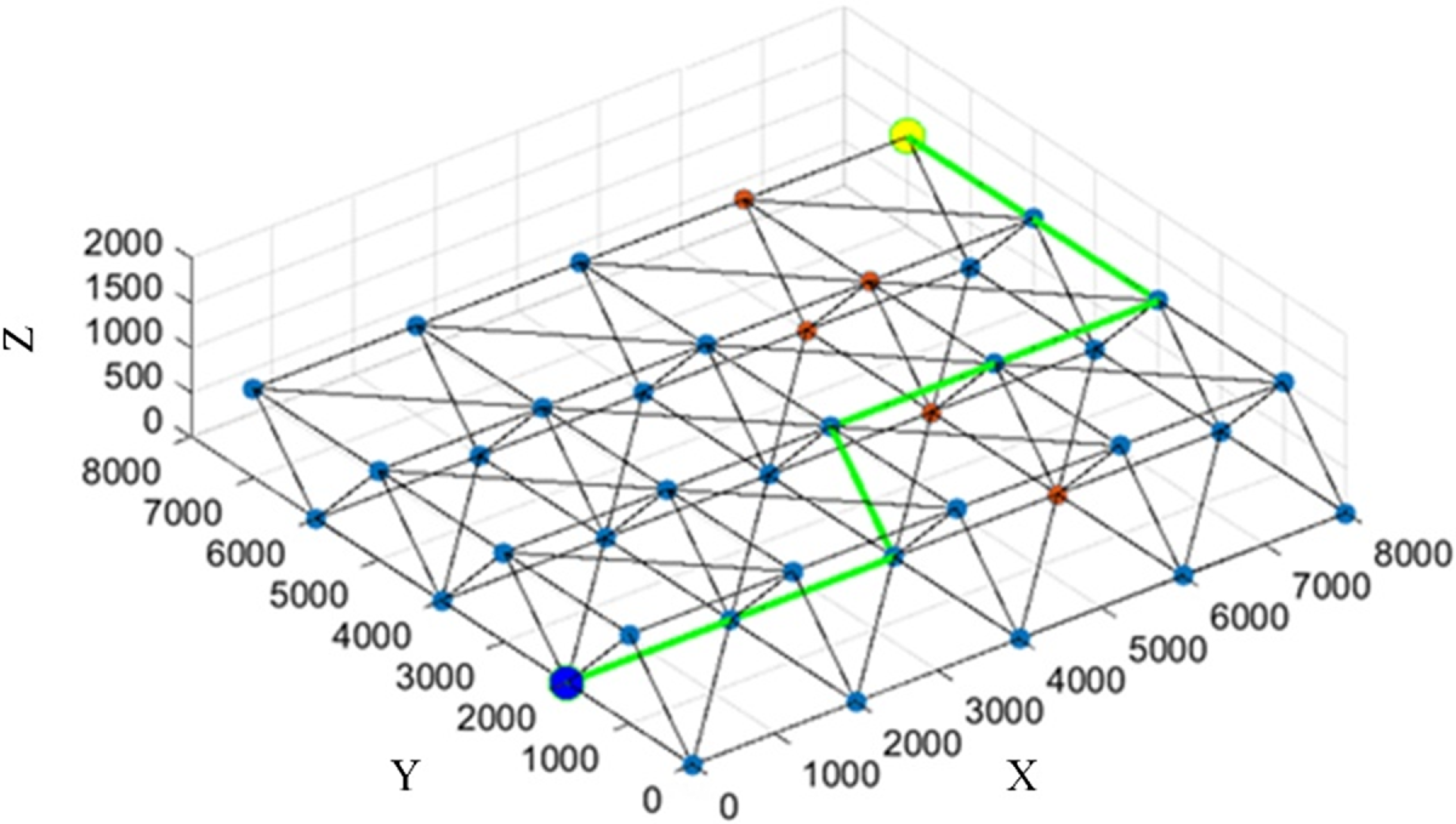
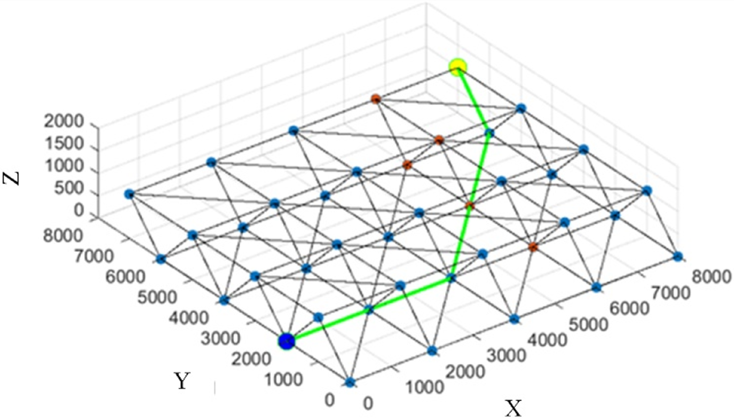
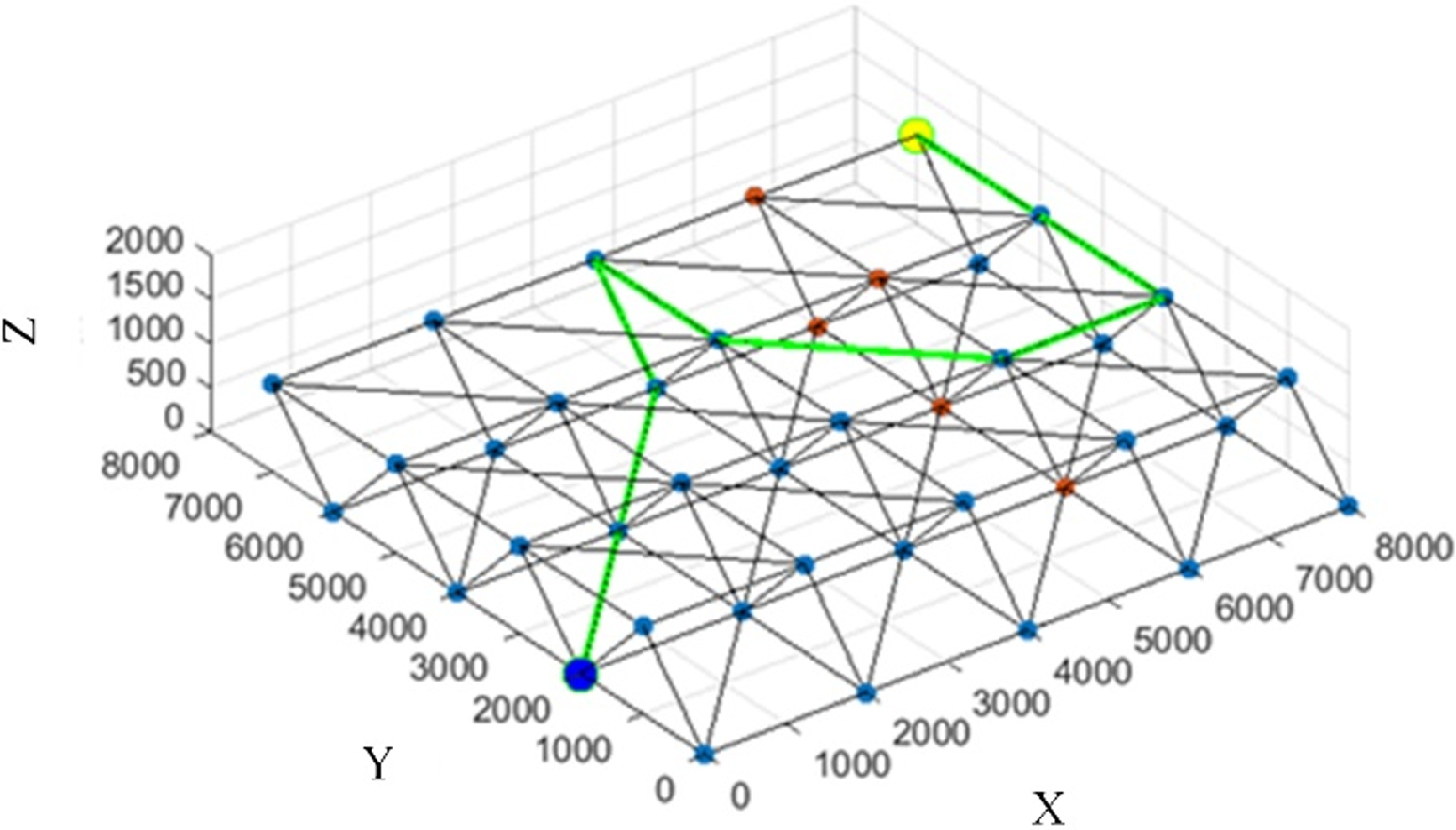
There may be some space manipulators or other working mobile mechanical equipment on the space truss, so the path planning sets up a special dynamic environment, there are dynamic obstacles on the truss, and it is necessary to plan the optimal path while avoiding the obstacles. Nodes 14, 15, 16, 35, and 36 are set as obstacle nodes, and obstacles appear when searching for the fourth node, until the target point is finally found. To improve the reliability of the simulation experiment results, the improved LPA-star algorithm, the unimproved LPA-star algorithm, and the improved A-star algorithm are used to simulate the dynamic path planning problem, respectively, and the simulation results are shown in Figure 13, Figure 14 and Figure 15.
Simulation path diagram of the improved Lifelong Planning A-star algorithm.

Simulation path diagram of the unimproved Lifelong Planning A-star algorithm.

Simulation path diagram of the improved A-star algorithm.

The simulation results show that the optimal path searched using the improved LPA-star algorithm passes through the nodes: 2→6→10→30→34→38→39→40, the optimal path length is 13,414 mm, and the algorithm’s search time is 0.0149 s, which indicates that the improved LPA-star algorithm can complete the dynamic path planning task.
The simulation results show that the optimal path searched using the unimproved LPA-star algorithm passes through the nodes: 2→6→10→15→20→40, the optimal path length is 11,071 mm, and the algorithm’s search time is 0.0262 s, but in the fourth exploration, the current position and the obstacle happen to be the same point. In reality, the robot should avoid appearing at the same location as the obstacle, which gives rise to the shortcomings of the unimproved LPA-star algorithm mentioned in the previous section, indicating that using the unimproved LPA-star algorithm is unable to complete the dynamic path planning task in this case.
The simulation results show that the optimal path searched using the improved A-star algorithm passes through the nodes: 2→7→12→32→31→34→38→39→40, the optimal path length is 17,899 mm, and the algorithm’s search time is 0.0328 s, which indicates that the improved A-star algorithm can complete the dynamic path planning task.
The simulation results show that both improved algorithms can meet the task requirements of dynamic path planning, indicating that the improved algorithms can indeed solve the dynamic path planning problem and prove the effectiveness of the improved algorithms. Both algorithms can search the optimal path from the start point 2 to the goal point 40, but the lengths of the searched paths are not equal, and the length of the searched paths of the improved LPA-star algorithm is smaller than that of the improved A-star algorithm. Compared with the unimproved LPA-star algorithm, it can be shown that the design of the improved LPA-star algorithm for planning is very effective, which proves the superiority of the improved LPA-star algorithm. From the point of view of the algorithm searching time, the improved LPA-star algorithm searching time is shorter than the improved A-Star algorithm, which indicates that the improved LPA-star algorithm has higher searching efficiency and better searching performance in the dynamic environment.
5. Conclusion
In this paper, a new cellular robot structure is proposed for the path-planning problem of cellular robot in space truss. On this basis, an improved LPA-star algorithm is proposed, and the improved LPA-star algorithm is utilized to solve the optimal path problem of the robot in the truss moving process.
The main findings and conclusions of this paper are as follows:
-
1. A cylindrical multifunctional cellular robot module was designed, then the cellular robot anatomy was analyzed and designed, and a basic anatomical scheme for a six-degree-of-freedom cellular robot was proposed;
-
2. An improved LPA-star algorithm and an improved A-star algorithm are proposed;
-
3. The mathematical model of the space truss was established, the algorithmic process of finding the optimal path planning was planned, and the dynamic map environment was set up. Simulation results show that both improved algorithms can accomplish the dynamic path planning task under the environment set up in this paper, but compared with the improved A-star algorithm, the optimal path length of the improved LPA-star algorithm is shortened by about 25%, and the algorithm search time is shortened by about 55%. Thus, the improved LPA-star algorithm possesses shorter optimal paths and higher search efficiency.
Of course, this study has some shortcomings:
-
1. The robot designed in this paper could also have a more complex anatomy, and the functionality and motor performance it possesses remain to be investigated;
-
2. There are many uncertainties in the real environment, such as sensor errors, lack of actuator accuracy, etc., which can lead to deviations between the plan and the actual situation. The LPA-star algorithm, as a probability-based approach, can alleviate this problem to some extent, and future research on the motion control aspects of cellular robots can continue to be explored.
Author contribution
The research work of this paper is the result of the joint efforts of the whole team. Conceptualization: Ye Dai and Weijian Lv; Methodology: Ye Dai and Weijian Lv; Software: Weijian Lv; Validation: Ye Dai and Muyan Zong; Investigation: Shikun Li; Writing – original draft preparation: Weijian Lv; Writing – review and editing: Ye Dai and Muyan Zong. All authors have read and agreed to the published version of the manuscript.
Financial support
This research was supported by the National Natural Science Foundation of China [grant number 52075134], and the Joint Guidance Project of Natural Science Foundation of Heilongjiang Province of China [grant number LH2019E062].
Competing interests
The authors declare that they have no financial or non-financial conflict of interest.
Ethical approval
The authors declare that this work is original and does not include experiments with animals.