


I. INTRODUCTION
The wire medium (WM), a classical artificial-dielectric material made of a periodic arrangement of metal wires placed along one, two, or three spatial directions, has been receiving increasing consideration since the discovery of its rather unique spatially dispersive nature [Reference Belov, Marqués, Maslovski, Silveirinha, Simovski and Tretyakov1]. In particular, planar structures, including WM layers with different wire orientations have been studied in the last decade by various authors, considering both transmission properties for propagation across the WM layers [Reference Belov, Simovski and Ikonen2, Reference Ono, Kato and Kawata3], dispersion properties for modal propagation along the layers [Reference Nefedov and Viitanen4–Reference Yakovlev, Silveirinha, Luukkonen, Simovski, Nefedov and Tretyakov6], and radiation from WM-loaded planar antennas [Reference Burghignoli, Lovat, Capolino, Jackson and Wilton7–Reference Silveirinha and Maslovski10].
In this paper, we analyze closed and open planar structures loaded by a WM slab having vertically aligned wires (see Fig. 1) adopting a recently introduced effective network formalism [Reference Comite, Baccarelli, Burghignoli, Di Ruscio and Galli11–Reference Comite, Burghignoli, Baccarelli, Di Ruscio and Galli13]. Such a transmission-line formulation, which takes into account the anisotropic and spatially dispersive nature of the WM by including the additional waves existing in the WM layers and the associated additional boundary conditions [Reference Silveirinha14], allows for a more direct and efficient analysis of the considered structures if compared with the more cumbersome field-matching approach or full-wave approaches.
Example of planar structure including WM: a PPW, whose upper plate is made of a partially reflecting surface (e.g., an array of metal patches), partially loaded by a WM slab with vertically aligned wires.

In particular, in this paper we will focus on the derivation of the structure Green's functions in the spectral domain, whose singularities in the complex plane of the relevant radial wavenumber allow for, e.g., assessing the role of the involved surface or leaky waves. Dispersion and radiation properties, obtained through the proposed network formalism by using the transverse-resonance technique and the reciprocity theorem, respectively, will be illustrated for a class of Fabry–Perot cavity antennas (FPCAs) [Reference Jackson, Oliner and Balanis15] based on a partially open WM-loaded parallel-plate waveguide (PPW), for which leaky unimodal regimes are achieved by minimizing undesired radiation from the quasi-transverse electromagnetic (TEM) mode.
II. EQUIVALENT-NETWORK ANALYSIS OF WM-LOADED PLANAR STRUCTURES
A) Equivalent-network model of a dielectric/WM interface
As first shown in [Reference Belov, Marqués, Maslovski, Silveirinha, Simovski and Tretyakov1], the WM can be considered in the large wavelength limit as a homogenous medium having both anisotropic and spatially dispersive behavior, with a dyadic permittivity expressed in the spectral domain as (see the reference frame of Fig. 1)
 $${\underline {\bi \varepsilon } = \varepsilon _0\varepsilon _{rh}} \left[{{\bf u}_x{\bf u}_x + {\bf u}_y{\bf u}_y + } \left({1 - \displaystyle{{k_p^2 } \over {\varepsilon _{rh}k_0^2 - k_z^2 }}}\right){{\bf u}_z{\bf u}_z}\right], $$
where z is the direction of alignment of the wires, ε0 is the vacuum permittivity, ε rh is the relative permittivity of the host medium in which the wires are embedded, k 0 is the free-space wavenumber, k p = 2πf p /c and f p is the plasma frequency, whose approximate expression as a function of the wire radius a and the wire spacing p is [Reference Belov, Marqués, Maslovski, Silveirinha, Simovski and Tretyakov1]
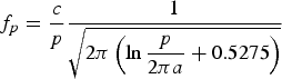 $$f_p = \displaystyle{c \over p} \displaystyle{1 \over {\sqrt {2\pi \left( {\ln \displaystyle{p \over {2\pi a}} + 0.5275} \right)} }} $$
valid for a ≪ p ≪ λ 0.
An exponential dependence on the x and y coordinates [i.e., exp ( − j(k
x
x + k
y
y))] is now assumed (see Fig. 1), as appropriate for fields in the spectral domain or for problems of plane-wave incidence. Without loss of generality, we may also let k
y
= 0, thus obtaining a two-dimensional (2D) problem. Under these conditions, as is well known, Maxwell's equations split into two separate sets, one for TE
z
and one for TM
z
fields. The TE wave is the ordinary wave of the WM as a uniaxial medium: its electric field is orthogonal to the wires and it does not interact with the wires; hence, it sees an ordinary isotropic medium with relative permittivity ε⊥ = ε
rh
. In the TM case, assuming
 $k_z^2 \ne \varepsilon _{rh} k_0^2 $
, we obtain the extraordinary wave of the uniaxial medium; assuming instead
 $k_z^2 = \varepsilon _{rh} k_0^2 $
, we have
 $\varepsilon _{\rm \parallel} \to \infty $
; hence E
z
→ 0 and a TEM
z
wave is obtained (this is the additional wave existing in the WM due to its spatially dispersive nature [Reference Belov, Marqués, Maslovski, Silveirinha, Simovski and Tretyakov1]).
As shown in [Reference Comite, Burghignoli, Baccarelli and Galli12, Reference Comite, Burghignoli, Baccarelli, Di Ruscio and Galli13], the TM or TEM subsets of Maxwell's equations can be written as transmission-line equations:
 $$\eqalign{& \displaystyle{{dV^{TM{\rm /}TEM}} \over {dz}} = - jk_z^{TM{\rm /}TEM} Z_c^{TM{\rm /}TEM} I^{TM{\rm /}TEM}, \cr & \displaystyle{{dI^{TM{\rm /}TEM}} \over {dz}} = - jk_z^{TM{\rm /}TEM} Y_c^{TM{\rm /}TEM} V^{TM{\rm /}TEM},} $$
where V TM/TEM = E y and I TM/TEM = −H x , and
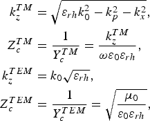 $$\eqalign{k_z^{TM} &= \sqrt {\varepsilon _{rh} k_0^2 - k_p^2 - k_x^2}, \cr Z_c^{TM} &= \displaystyle{1 \over {Y_c^{TM}}} = \displaystyle{{k_z^{TM}} \over {\omega \varepsilon _0 \varepsilon _{rh}}}, \cr k_z^{TEM} &= k_0 \sqrt {\varepsilon _{rh}}, \cr Z_c^{TEM} &= \displaystyle{1 \over {Y_c^{TEM}}} = \sqrt {\displaystyle{{\mu _0} \over {\varepsilon _0 \varepsilon _{rh}}}},} $$
Let now the plane z = 0 be the interface between a half-space (z > 0) filled with an ordinary dielectric medium having relative permittivity ε rs (e.g., air), and a half-space (z < 0) filled with a WM. In the TE case, the standard boundary conditions at z = 0 (i.e., the continuity of the tangential components of the electric and magnetic fields) require voltages and currents to be continuous at the interface. This results in a two-port representation consisting in the usual direct connection of the two lengths of the equivalent transmission lines associated with the TE waves in the two half-spaces. On the other hand, in the TM case the presence of an additional wave in the WM requires the air/WM interface to be represented by a three-port network, as shown in Fig. 2. As a matter of fact, the standard boundary conditions require that the total voltages and currents be continuous at the interface:
 $$\eqalign{& V_ + ^{TM} = V_ - ^{TM} + V_ - ^{TEM}, \cr & I_ + ^{TM} = I_ - ^{TM} + I_ - ^{TEM},} $$
Transmission-line equivalent network for an air/WM interface.

Furthermore, as demonstrated for the first time in [Reference Silveirinha14], the presence of an additional wave in z < 0 requires an additional boundary condition (ABC) at z = 0, that can be written as
 $$\varepsilon _{rs} \left. {E_z} \right \vert _{z = 0^ +} = \varepsilon _{rh} \left. {E_z} \right \vert _{z = 0^ -}. $$
By exploiting the TM and TEM transmission-line equations (3) it can be shown, after some algebra, that the three-port network model of an air/WM interface presented in Fig. 2 can be described by the following constitutive relations [Reference Comite, Burghignoli, Baccarelli, Di Ruscio and Galli13]:
 $$\left\{ {\matrix{ {V = V_2 + V_{31},} \cr {\hskip -1.5pcI_2 = - \xi I_1,} \cr {I_3 = (\xi - 1)I_1,} \cr}} \right.$$
where
 $$\xi = \displaystyle{{k_x^2} \over {k_x^2 + k_p^2}} $$
and V i , I i with i = 1, 2, 3 are the voltages and currents at the ports of the three-port network as shown in Fig. 2.
B) Near fields excited by prescribed sources
From the three-port network representation of a dielectric/WM interface it is straightforward to derive the ABCD matrix of a WM layer of thickness h (see [Reference Comite, Burghignoli, Baccarelli, Di Ruscio and Galli13] for the resulting, rather lengthy expressions of the matrix elements). Once this is available, it is then possible to derive the equivalent-network model for any planar structure comprising an arbitrary number of WM layers.
An important application of such model is the determination of the dyadic Green's functions of the structure in the spectral domain, which are needed e.g., for the evaluation of the near field excited by prescribed electric or magnetic sources. We will illustrate here the procedure considering the case of a vertically directed electric–current source, rotationally symmetric around the z-axis and placed on the bottom metal plate of a partially open WM-loaded PPW as in Fig. 1:
 $${\bf J}_i = {\bf u}_z J_{Sz} (\rho )\delta (z + h),$$
where J Sz is a vertical surface current density [A/m]. By letting J Sz = P 0 δ(ρ)/(2πρ), the case of a vertical electric dipole (VED) of amplitude P 0 [A/m] is recovered, which can be used as a first approximate model for, e.g., a coaxial-probe excitation.
This source excites a purely TM z field and is rotationally symmetric around the z-axis. The structure is also assumed to be rotationally symmetric around the z-axis once both the WM layer, the PRS and the upper partially reflecting surface (PRS) are homogenized; note that the homogenized WM with vertical wires is uniaxial with the z-axis as optical axis; hence, it is certainly rotationally invariant in the xy-plane; as concerns the PRS, its equivalent surface impedance is also assumed to be rotationally invariant in the xy-plane (as is the case for, e.g., a 2D-periodic array of square patches with square unit cell, or an annular arrangement of arbitrary metal patches [Reference Di Ruscio, Burghignoli, Baccarelli and Galli16]). The rotational symmetry of both the source and the structure implies that an azimuthally symmetric TM field is excited, with non-zero components H ϕ , E ρ , and E z .
From the well-known expressions for the spectral dyadic Green's functions of multilayered media (see, e.g., [Reference Michalski and Mosig17]), the following integral representation can be derived for, e.g., H ϕ :
 $$H_\phi (\rho, z) = \displaystyle{j \over {2\omega \varepsilon}} \int_0^{ + \infty} \hat I_V^{TM} (z,k_\rho )\tilde J_{Sz} (k_\rho )J_1 (k_\rho \rho )k_\rho ^2 dk_\rho, $$
where J
1 is the Bessel function of first kind of order 1. Here ε is the permittivity of the dielectric layer where the source is located;
 $\hat I_V^{TM} $
is the current at z produced by a unit-amplitude voltage generator placed at z = −h on the equivalent network of the structure (see Fig. 3, configuration ‘A’); finally,
 $\tilde J_{Sz} $
is the Fourier-Bessel transform of order 0 of J
Sz
:
 $$\tilde J_{Sz} (k_\rho ) = \int_0^{ + \infty} J_{Sz} (\rho )J_0 (k_\rho \rho )\rho d\rho $$
where J
0 is the Bessel function of the first kind of order 0 (in particular, for a VED of amplitude P
0 it results
 $\tilde J_{Sz} = P_0 /(2\pi )$
[A/m]).
Equivalent networks used for the calculation of the spectral Green's function for the azimuthal magnetic field produced by a VED.

In order to calculate the magnetic field on the aperture plane z = 0+ (i.e., just above the PRS) the current
 $\hat I_V^{TM} (0^ + , k_\rho )$
is thus required. The latter can be obtained considering the configuration ‘B’ in Fig. 3 since, by virtue of the reciprocity theorem for networks, it results I
A
(0+) = I
B
( − h). In the network ‘B’ it results
 $$\eqalign{& V^B (0) = V_g \displaystyle{{Y_0} \over {Y_0 + Y^{\prime}_{in}}}, \cr & I^B (0^ + ) = V_g \displaystyle{{Y_0 Y^{\prime}_{in}} \over {Y_0 + Y^{\prime}_{in}}},} $$
where Y′ in is the input admittance at z = 0+ looking downwards. Such input admittance can be obtained as Y′ in = Y PRS + A/B in terms of the equivalent admittance of the PRS and of the elements A,B of the ABCD matrix of the two-port network accessible at the transmission-line sections z = −h and z = 0. As shown in Fig. 3 (right), such two-port network is the cascade of two lengths of transmission line and of the two-port network that models the WM layer; therefore, its ABCD matrix is simply the product of the ABCD matrices of the cascaded constituents.
C) Leaky-wave field (LWF)
The spectral and non-spectral constituents of the aperture field can be obtained by extending the integration in (10) along the entire k
ρ
-axis [using the identity
 $J_1 (z) = (1/2)(H_1^{(2)} (z) + H_1^{(2)} ( - z))$
, where
 $H_1^{(2)} (z)$
is the Hankel function of first order and second kind], and then customarily closing the integration contour in the lower half of the complex k
ρ
plane. In particular, the contribution to the aperture field of a leaky pole at k
ρ
= k
ρLW
(LWF) can be calculated through the residue theorem and results in the following cylindrical leaky wave for the magnetic field:
 $$H_\phi ^{LW} = \displaystyle{\pi \over {\omega \varepsilon}} k_{\rho LW}^2 {\rm Res}\left[ {\hat I_V^{{\rm TM}} (0^ +, k_\rho );k_{\rho LW}} \right]H_1^{(2)} (k_{\rho LW} \rho )$$
The electric field radiated in the far region by such a leaky-wave aperture field can then be calculated using the formulas provided in [Reference Ip and Jackson18] as
 $$E_\theta ^{LW} = E_0 R(r)P(\theta ),$$
where
 $$E_0 = \displaystyle{{2\pi} \over {\omega \varepsilon}} k_{\rho LW} {\rm Res}\left[ {\hat I_V^{{\rm TM}} (0^ +, k_\rho );k_{\rho LW}} \right]$$
and (for an infinite aperture plane)
 $$\eqalign{& R(r) = - \displaystyle{{j\omega \mu _0} \over {4\pi r}}e^{ - jk_0 r}, \cr & P(\theta ) = - 4\displaystyle{{k_0 \sin \theta} \over {k_\rho ^2 - k_0^2 \mathop {\sin} \nolimits^2 \theta}}.} $$
D) Total, radiated, and surface-wave power
The total complex power produced by the source can be calculated using Poynting theorem as
 $$P_{tot} = - \displaystyle{1 \over 2}\int J_{Sz}^* E_z dS_{xy}. $$
This can also be cast in the form of a spectral-domain integral as
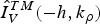
 $$P_{tot} = \displaystyle{\pi \over {\omega ^2 \varepsilon ^2}} \int_0^{ + \infty} k_\rho ^3 \left \vert {\tilde J_{Sz} (k_\rho )} \right \vert ^2 \hat I_V^{TM*} ( - h,k_\rho )dk_\rho $$
Note that, since
 $\hat I_V^{TM} ( - h,k_\rho )$
behaves asymptotically as
 $k_\rho ^{ - 1} $
for large k
ρ
, the convergence of the integral at infinity depends on the asymptotic behavior of the factor
 $\tilde J_{Sz} (k_\rho )$
; in particular, for a VED source the integral is not convergent at infinity. However, this affects only the reactive part of the total power (which is infinite for a dipole source, as is well known). The real (active) part of the total power remains always finite and for a VED of amplitude P
0 it is given by the sum of two contributions: the radiated power P
r
, given by the portion of the integral along the visible spectrum, 0 ≤ k
ρ
≤ k
0:
 $$P_r = \displaystyle{1 \over {4\pi \omega ^2 \varepsilon ^2}} \left \vert {P_0} \right \vert ^2 \int_0^{k_0} k_\rho ^3 \hat I_V^{TM} ( - h,k_\rho ) dk_\rho \;,$$
and the surface-wave power P
sw
, given by the residue contribution of surface-wave poles
 $k_\rho ^{SW} \gt k_0 $
(if any) on the real axis:
 $$P_{sw} = \displaystyle{1 \over {2\omega ^2 \varepsilon ^2}} \left \vert {P_0} \right \vert ^2 (k_\rho ^{SW} )^3 B_{SW} $$
where
 $$jB_{SW} = {\rm Res}[\hat I_V^{TM} ( - h,k_\rho );k_\rho ^{SW} ].$$
III. NUMERICAL RESULTS
In this section, numerical results will be provided to illustrate modal and radiation features of WM-loaded PPWs. In particular, the results concerning the dispersive analysis of closed and open WM-loaded PPWs will be derived by applying the condition of transverse resonance to the presented network approach (transmission-line model, TLM) and will be first compared with those obtained with a standard and more cumbersome field-matching technique (FMT). Then, modal dispersion behaviors will be further validated against a multimodal Bloch-wave analysis based on the full-wave simulation of a truncated structure [Reference Bongard, Perruisseau-Carrier and Mosig19, Reference Valerio, Paulotto, Baccarelli, Burghignoli and Galli20] performed with a commercial electromagnetic software (i.e., CST) [21]. Furthermore, radiation features of the proposed open configuration will be obtained by applying a well-known approach based on reciprocity theorem and using the proposed network representation (TLM) or the FMT [Reference Comite, Burghignoli, Baccarelli, Di Ruscio and Galli13]. Then, the radiation features will be validated with the radiation patterns obtained by CST, by using a single unit cell in a periodic environment and applying reciprocity. The leaky-wave contribution to the total radiated field will be evaluated by using the formulation derived in Section II.C) (LWF). Finally, the radiation efficiency of the proposed PPW-based FPCA will be reported by using the approach described in Section II.D).
A) Modal properties
The study of a closed PPW symmetrically loaded with a WM slab (see Fig. 1, where now the upper plate is a PEC wall) having different thicknesses is considered as a first example. In Figs 4 and 5 dispersion curves (β/k 0 versus f) for TEM, TM1, and TM2 modes are reported for t = 3 mm and t = 10 mm, respectively.
Dispersion curves (normalized phase constant versus frequency) for the first modes supported by an air-filled closed PPW loaded by a WM slab (see Fig. 1). Parameters: h=14.27 mm, WM slab thickness t = 3 mm, wire radius a = 0.19 mm, wire spacing p = 1.5 mm (plasma frequency f p = 91.8 GHz). FMT, field-matching technique; CST, CST Microwave Studio; TLM, our transmission-line model.

Dispersion curves for the TEM, TM1, and TM2 modes for the same structure presented in Fig. 4 but for t = 10 mm, a = 0.14 mm, p = 1 mm (plasma frequency f p = 150 GHz).

Results from the TLM are coincident with those obtained with the FMT and both have been validated by means of a multimodal Bloch analysis carried out with full-wave simulations on CST Microwave Studio. For increasing values of the thickness t the TEM mode becomes strongly perturbed, while both TM1 and TM2 modes interact less with the WM slabs. In particular, when t = 10 mm an asymptote is clearly visible for the TEM mode, which occurs for
 $f_A = c/(2t\sqrt {\varepsilon _{rh}} )$
(at about 14.5 GHz, for the structure considered in Fig. 5) [Reference Silveirinha, Fernandes and Costa22], thus allowing for a unimodal TM1 regime between 14.5 and 20 GHz. Since in the TE case the electric field is orthogonal to the wires, the wave does not interact with them and the TE1 and TE2 modes have the same dispersive behavior as in the absence of the WM slab.
Figure 6: Field configurations at different frequencies for the y component of the magnetic field of the TEM, TM1, and TM2 modes supported by a WM-loaded PPW as in Fig. 4. The frequency-independent field configurations in the absence of WM loading are also reported for comparison.
Field configurations at different frequencies for the y component of the magnetic field of the TEM, TM1, and TM2 modes supported by a WM-loaded PPW as in Fig. 4. The frequency-independent field configurations in the absence of WM loading are also reported for comparison.

In Fig. 6, field configurations for the y component of the magnetic field are reported at different frequencies for the TEM and TM modes supported by the two considered WM structures and compared with those of the same waveguide in the absence of the WM slab. It can be noted that the WM slab has a dramatic effect on the TEM mode, whose unperturbed field configuration is a constant. This is a consequence of the strong interaction between the TEM electric field, which is vertical, and the metal wires of the WM. On the contrary, the other two modes exhibit a behavior not considerably different from the unperturbed configuration.
In Fig. 7 modal curves are shown for the TEM and higher-order TM and TE modes of an open WM layered structure, with t = 8 mm, obtained by replacing the upper plate of the PPW with a homogenized PRS [Reference Luukkonen23, Reference Yakovlev, Zouhdi, Sihvola and Vinogradov24] (see the caption for all the relevant details). The considered PRS is a 2D array of square metal patches as shown in Fig. 1, with spatial period D along the x and y directions and slots of width w. The PRS has been modeled in the relevant equivalent network as a simple shunt admittance, whose expression is [Reference Luukkonen23–Reference Yakovlev, Padooru, Hanson, Mafi and Karbasi25]
 $$Y_{PRS} = \displaystyle{{2j\alpha _{grid}} \over {\eta _{eff}}} $$
with
 $$\alpha _{grid} = \displaystyle{{Dk_{eff}} \over \pi} \ln \csc \left( {\displaystyle{{\pi w} \over {2D}}} \right),$$
where
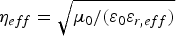 $\eta _{eff} = \sqrt {\mu _0 /(\varepsilon _0 \varepsilon _{r, eff} )} $
,
 $k_{eff} = k_0 \sqrt {\varepsilon _{r, eff}} $
, with
 $\varepsilon _{r, eff} = (\varepsilon _r + 1)/2$
(ε
r
= 1 for the case shown in Fig. 1). The choice D = 3 mm and w = 0.01 mm is made in all the presented numerical results.
Normalized phase and attenuation constant, β/k 0 (solid lines) and α/k 0 (dashed lines), respectively, versus frequency f for the TEM, TM1 and TM2 modes supported by a structure as in Fig. 4, where now the upper PPW plate is a PRS constituted by an array of square metal patches. Parameters: Slab thickness t = 8 mm; PRS spatial period D = 3 mm; slot width w = 0.01 mm. TLM, transmission-line model; FMT, field-matching technique; CST, CST Microwave Studio.

We note that for the open configuration the TM1 and TM2 modes are both improper leaky modes, [Reference Jackson, Oliner and Balanis15] with a complex propagation constant k x = β − jα, where β and α are the relevant longitudinal phase and attenuation constant, respectively. The results for the TEM, TM1, and TM2 modes obtained with the proposed TLM are again coincident with those obtained with the FMT. The agreement with full-wave results obtained through the multimodal Bloch analysis with CST is still quite good. We note that the TEM mode is a slow surface wave, which, if excited by an appropriate source, will not significantly contribute to the radiation pattern obtained from infinite structures, but can contribute to decrease the radiation efficiency of the FPCA. On the other hand, both TM1 and TM2 modes are improper leaky and fast, with sufficiently low values of the attenuation constant, and can thus produce directive radiation. In particular, the TM1 leaky mode presents a low-frequency leaky-wave cutoff (i.e., the frequency at which β = α) at about 12 GHz and becomes a slow wave above 22 GHz, which approximately corresponds to the low-frequency leaky-wave cutoff of the TM2 leaky mode. These dispersion features show the possibility of obtaining a single-beam scanning behavior from such a kind of open structure, if the TM1 leaky mode is properly excited. Also in this case, the TE1 and TE2 leaky modes have the same dispersive behavior as in the absence of the WM slab. We further note that their dispersive behavior remains close to that of the corresponding TM leaky modes, thus opening the possibility of obtaining conical beam scanning with the same beam angles for the two polarizations (further optimization is however needed to achieve a satisfactory TM/TE match).
In Fig. 8, field configurations for the y component of the magnetic field are reported at different frequencies for the TEM mode supported by the open WM structures and compared with those of the same waveguide in the absence of the WM slab. It can be noted that also in the open configuration the WM slab has a dramatic effect on the TEM mode, whose field configuration is increasingly confined inside the WM slab as the frequency approaches the asymptote frequency f A (equal to 18.75 GHz for t = 8 mm).
Field configurations at three frequencies for the y component of the magnetic field of the TEM mode supported by a WM-loaded open structure, whose modal properties are presented in Fig. 7. The frequency-independent field configurations in the absence of WM loading are also reported for comparison.

B) Radiative properties
In Figs 9–11, the radiative properties of the open WM-loaded PPWs in Fig. 1 used as FPCAs are investigated We assume that the chosen PRS, realized with a 2D array of square patches, can be homogenized and modeled as in (22) and (23) and hence it is isotropic. The antenna is excited by an azimuthally symmetric VED source placed on the lower metal plate and parallel to the z-axis. As a consequence, an almost omnidirectional radiation pattern is expected, with TM polarization (i.e., the electric far field is linearly polarized along
 ${\bf u}_\theta $
) [Reference Di Ruscio, Burghignoli, Baccarelli and Galli16]. The radiation patterns have been calculated in an arbitrary elevation plane, assuming a homogenized representation of the PRS.
Far-field radiation pattern at two different frequencies of the open structure not loaded by the WM slab obtained by reciprocity. The leaky-wave contribution for the main lobe (related to the radiation of the TM1) has also been reported for comparison by numerically evaluating the residue of the leaky pole of the relevant Green's function.

Far-field radiation pattern at two different frequencies of the open structure loaded by the WM slab as in Fig. 7. The leaky-wave contribution has also been reported for comparison as in Fig. 9. The validation is obtained through a full-wave simulation in a unit cell with Floquet-periodic boundary conditions has also been reported.

Radiation scanning behavior of the proposed structure as in Fig. 7: (a) normalized pattern in polar representation; (b) non-normalized Cartesian plot for the E-field radiation pattern at different frequencies.

In Fig. 9, the far-field radiation patterns are reported for a structure as in Fig. 1, but not loaded by the WM slab. A comparison is shown between the total far field obtained by reciprocity [Reference Comite, Burghignoli, Baccarelli, Di Ruscio and Galli13] and the leaky-wave far-field contribution [see eq. (14)] due to the TM1 leaky mode. An excellent agreement is observed between the main lobe and the TM1 LWF. However, a strong additional lobe can be observed with a maximum around 80°, due to leakage from the quasi-TEM mode, which could deteriorate the single-beam scanning behavior of a PPW-based FPCA working on the TM1 leaky mode.
In Fig. 10, the same structure is considered, now loaded by a WM slab with thickness t = 8 mm. As shown in Fig. 7, the TEM mode of this WM-loaded structure is bound and is a slow wave. As a consequence, its contribution to the radiation pattern of the infinite open PPW is effectively removed. In particular, we can observe that the main lobe (due to the TM1 leaky mode) remains virtually unaltered, while the secondary lobe (due to the quasi-TEM leaky mode) has been completely suppressed by the WM. A very good agreement can be observed between the total electric far field and the radiation pattern obtained by considering only the leaky-wave aperture field, while both methods have been further validated with the exact total radiation patterns obtained by simulating a single unit cell in a periodic environment with CST and by applying reciprocity.
In Fig. 11, radiation patterns for the structure loaded with a WM slab with thickness t = 8 mm are shown for different values of the frequency. In particular, in Fig. 11(a) the normalized radiation pattern is shown in a polar plot with a main beam-scanning behavior from about 50°–75° by varying frequency from 16 to 21 GHz. In Fig. 11(b), the same scanning behavior can be observed in a linear plot, where however the electric far field has not been normalized: an almost constant behavior is anyway observed for the amplitude of the electric far field at the pointing angles.
Finally, the radiation efficiency η of the considered antenna can be evaluated, defined as
 $$\eta = \displaystyle{{P_r} \over {P_{sw} + P_r}}, $$
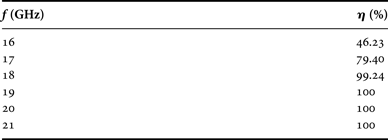
where P r and P sw are the total radiated power and the surface-wave power, given by (19) and (20), respectively. In Table 1 the radiation efficiency is reported for a structure as in Fig. 11; it can be noted that, by increasing frequency, the efficiency increases until it reaches and maintains the value of 100%. This can be explained considering that the modal field of the TEM surface wave is more and more confined inside the WM layer as frequency is increased; thus, its coupling to the VED source placed on the bottom plate of the PPW monotonically decreases. Once the frequency of the vertical asymptote of the TEM dispersion curve is reached, the surface wave ceases to exist; hence, the total active power delivered by the source becomes exactly equal to the power radiated in the space.
Radiation efficiency of the proposed antenna for different frequencies.
IV. CONCLUSION
Planar layered structures loaded with vertically aligned WM slabs have been analyzed by means of a novel transmission-line approach. Thanks to the proposed network formalism, the dispersion equation can suitably be determined using the transverse-resonance technique. Modal properties and dispersion curves of both closed and open planar waveguides loaded with symmetrically placed WM slabs have been reported and discussed. The results have been validated against those obtained with the more cumbersome field-matching approach and by means of a multimodal Bloch analysis carried out on data obtained through full-wave simulations on a commercial CAD tool. The evidence of interesting dispersive effects is emphasized, concerning unimodal leaky-wave regimes through the suppression of the radiative contribution of an undesired TEM leaky mode.
The radiation features of a class of FPCAs excited by an azimuthally symmetric VED source have been investigated through the proposed network formalism, by deriving the spectral-domain Green's function of a partially open WM-loaded PPW. The contribution of the desired TM1 leaky pole to the aperture field has been calculated, the relevant electric field radiated in the far region has been assessed, and an excellent agreement between the total far field and the TM1 LWF has been found. Finally, the radiation efficiency of the considered antenna has been evaluated, showing that the power radiated in the space approaches the total active power delivered by the source when the TEM surface wave is properly suppressed by the WM slab.
 Davide Comite received the Master's degree (cum laude) in Telecommunications Engineering in 2011 and the Ph.D. degree in Electromagnetics and Mathematical Models for Engineering in 2015 from ‘Sapienza’ University, Rome, Italy, where he is now a postdoctoral researcher. His scientific interests mainly involve study and design of dual-pol leaky-wave antennas, modal analysis to characterize radiation in planar structures, and ground-coupled antennas for geophysical and space applications. He is also interested in inverse problems, specifically in microwave tomographic algorithms applied to numerical and measured GPR data, considering down-looking as well as forward-looking configurations. His activity also regards techniques of numerical characterization and experimental approaches for the study of electromagnetic subsurface propagation and scattering effects by means of GPR systems. He was the recipient of the ‘Marconi Junior 2012’ prize, awarded by Fondazione Guglielmo Marconi to young student author of master degree thesis particularly relevant and important in ICT.
 Paolo Baccarelli received the Laurea degree in electronic engineering and the Ph.D. degree in applied electromagnetics from “La Sapienza” University of Rome, Rome, Italy, in 1996 and 2000, respectively. In 1996, he joined the Department of Electronic Engineering, “La Sapienza” University of Rome, where he has been an Associate Researcher from 2000 to 2008, a Temporary Professor of Electromagnetics from 2005 to 2010, and an Assistant Professor since November 2010. From April 1999 to October 1999, he was a Visiting Researcher with the University of Houston, Houston, TX, USA. His research interests include guided-wave theory with stress on surface waves and leaky waves in anisotropic media, metamaterials, graphene and electromagnetic band-gap structures, numerical methods for the analysis of uniform and periodic passive printed microwave structures, analysis and design of uniform, and periodic traveling wave antennas.
 Paolo Burghignoli was born in Rome, Italy, on February 18, 1973. He received the Laurea degree (cum laude) in Electronic Engineering in 1997 and the Ph.D. degree in Applied Electromagnetics in 2001, both from Sapienza University of Rome. In 1997, he joined the Department of Electronic Engineering, now Department of Information Engineering, Electronics and Telecommunications, Sapienza University of Rome, where he has been an Assistant Professor since November 2010 and an Associate Professor since November 2015. From January to July 2004, he was a Visiting Research Assistant Professor with the University of Houston, Houston, TX, USA. His research interests include planar antennas and arrays, leakage in uniform and periodic structures, numerical methods for integral equations, metamaterials, and graphene electromagnetics. Dr. Burghignoli was the recipient of the 1996/97 IEEE “Giorgio Barzilai” Laurea Prize, of a 2003 IEEE MTT-S Graduate Fellowship, and of a 2005 IEEE AP-S Raj Mittra Travel Grant.
 Alessandro Galli received the Laurea degree in Electronic Engineering and the Ph.D. in Applied Electromagnetics from Sapienza University of Rome, Italy. In 1990, he joined the Department of Electronic Engineering (now Department of Information Engineering, Electronics and Telecommunications) of Sapienza University for his research and educational activities. In 2000, he became an Assistant Professor, and in 2002 an Associate Professor at the Faculty of Engineering of Sapienza University. In 2013, he won the National Scientific Qualification as a Full Professor in the sector of Electromagnetics. He authored more than 300 papers on journals, books, and conferences. His research interests include theoretical and applied electromagnetics, mainly focused on modeling, numerical analysis, and design of microwave antennas and passive devices. Other research areas involve geoelectromagnetics, bioelectromagnetics, and microwave plasma heating for alternative energy sources. Dr. Galli received various international and national prizes for his research activity. He was a member of the Board of Directors of the European Microwave Association (EuMA) for the 2010–2012 and 2013–2015 triennium. He was the General Co-Chair of the European Microwave Week 2014. Since its foundation in 2012, he has been the Coordinator of the European Courses on Microwaves (EuCoM), the first European educational institution on microwaves.



