1. INTRODUCTION
Global positioning system (GPS) is used to calculate the position of a user anywhere in the world and the accuracy of this system has been enhanced during the last few years. Unfortunately, a real-time GPS service cannot guarantee the reliability and precision required for some applications, such as aircraft navigation (ESA, 2011). Satellite-based augmentation systems (SBAS) have been developed to overcome the limitations of GPS measurements related to precision and integrity.
The basic function of this system, aims to improve positioning accuracy by correcting several error sources affecting GPS signals and to provide integrity data to the users. The corrections transmitted by SBAS contribute to mitigate the ranging error sources related to satellite clocks, satellite position and ionospheric effects. The other errors (tropospheric effects, multipath and user receiver contributions) are local effects which cannot be corrected by augmentation systems.
SBAS consist of widely dispersed reference stations each of which monitors and gathers data from GPS satellites. These data are forwarded to the master station for processing to determine the integrity and differential corrections for each monitored satellite (Krasuski, Reference Krasuski2017). The integrity information and differential corrections are then sent to a ground earth station, uplinked to geostationary satellites and broadcast to users (Kaplan and Hegarty, Reference Kaplan and Hegarty2006).
Several countries have implemented their own SBAS. European Geostationary Navigation Overlay System (EGNOS) is the European satellite-based augmentation system; it covers Europe and North Africa with the possibility of extending to include all of Africa and the Middle East (El-Rabbani, Reference El-Rabbani2002).
EGNOS consists of a space segment of three geostationary satellites and a ground segment with a network that includes 40 ranging and integrity monitoring stations (RIMS) (ESA, 2019). RIMS are the key components of the system; they are used for gathering raw data to provide differential corrections and integrity. Figure 1 shows the current locations of RIMS, represented by red points. It is clearly seen that Algeria is not included in the RIMS network. Algeria is the largest country in Africa, bordering the Mediterranean Sea between Morocco and Tunisia. It is located between latitudes 18° and 38° North and longitudes 9° West and 12° East.
Locations of EGNOS RIMS stations.

This study is a contribution to optimise the use of EGNOS open service (standard positioning service), which was first provided in 2009. This service is intended to offer a wide range of benefits to users for general purpose applications which require real-time metric precision (e.g., agriculture, road transport, maritime domain) but where safety is not critical, or those for which accuracy to within a metre or less is necessary (geodetic techniques, etc.) (ESA, 2017).
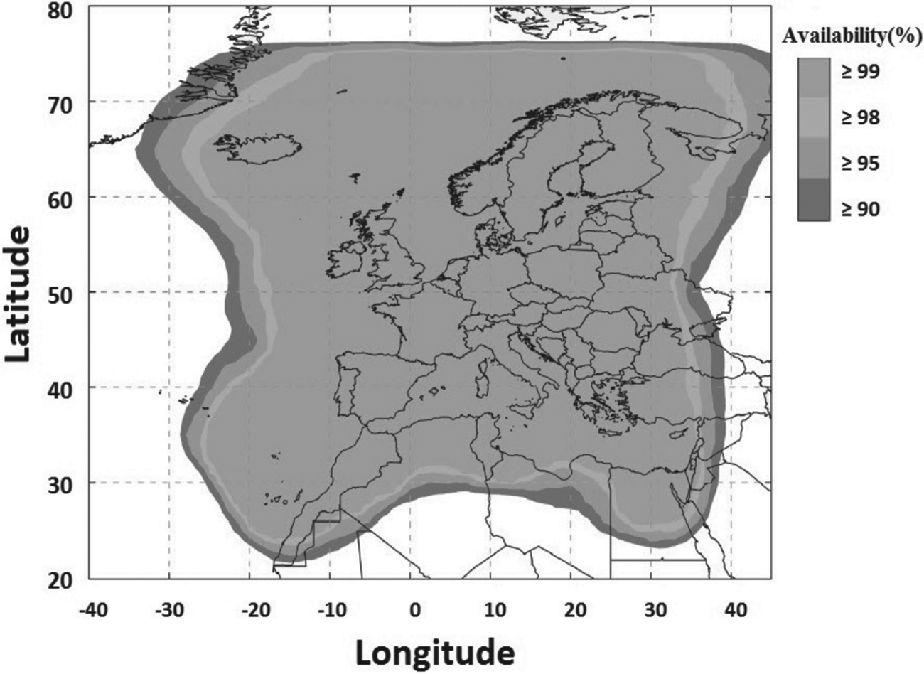
In the EGNOS open service provision area, the requirements for horizontal and vertical accuracy are that 95% of horizontal and vertical navigation system errors should be less than 3 m and 4 m, respectively. Figure 2 represents the availability of the EGNOS system; the use of EGNOS open service is possible beyond the grey area, however, its performance will be gradually degraded as the user moves away from it.
EGNOS open service availability area (horizontal position error < 3 m and vertical position error < 4 m), published in Open Service Definition Document (ESA, 2017).

Preliminary analysis was carried out to investigate the improvement in position accuracy with the help of EGNOS correction messages. The navigation and observation data of the GPS system in the Receiver Independent EXchange (RINEX) format were recorded through the Trimble NetR9 multifrequency receiver, positioned at four sites in Algeria. The positioning errors of GPS and GPS with EGNOS were calculated by comparison with the reference precise position for each site.
2. SBAS SIGNAL SPECIFICATION
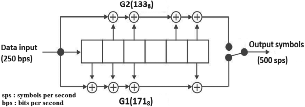
The SBAS correction signal is broadcast on 1,575·42 MHz L1 frequency with 1·023 binary phase shift keying (BPSK) spread spectrum modulation by a C/A code of PRN 120 to 138. The data are always half convolutional encoded rate with a forward error correction code (Hofmann-Wellenhof et al., Reference Hofmann-Wellenhof, Lichtenegger and Wasle2008). Therefore, the symbol rate that the GPS receiver must process is 500 symbols per second. The convolutional coding has a constraint length 7, as standard for Viterbi decoding, with a convolutional encoder logic arrangement as illustrated in Figure 3 (De Lellis et al., Reference De Lellis, Corraro, Ciniglio, Canzolino, Garbarino, Gaglione and Nastro2009).
Convolutional encoding.

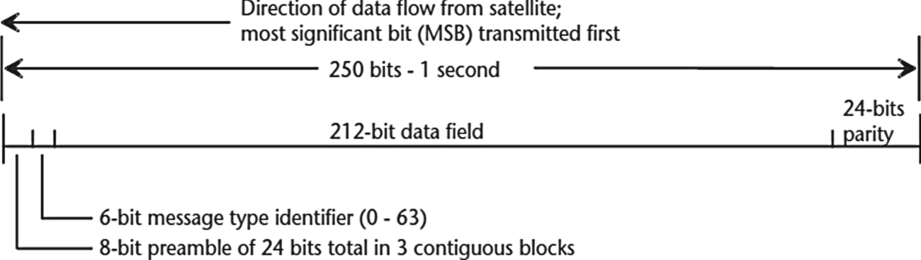
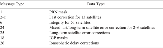
The 250-bits per second data from each SBAS is packed into 1 s blocks. Each block includes an 8-bit preamble (one of three parts of a 24-bit unique word, 01010011 10011010 11000110), a 6-bit message-type field (allowing for up to 64 message types), and a 212-bit payload with unique meaning specifically defined for each message type (see Table 1); the last 24 bits correspond to the parity bits, which ensure that the data were not corrupted during transmission (no bit error), as shown in Figure 4 (ESA, 2011; Kaplan and Hegarty, Reference Kaplan and Hegarty2006).
SBAS data block format.

Differential correction messages for SBAS.

EGNOS generates three types of differential corrections, as summarised in Table 1.
In addition to differential corrections, the SBAS system also monitors and broadcasts the integrity of GPS satellite signals. With integrity information, the user can determine which satellites are usable for reliable positioning computation (Liu et al., Reference Liu, Chen, Chen, Kröger and Pei2012).
3. APPLICATION OF DIFFERENTIAL CORRECTIONS
The components of satellite corrections are spread across many messages in the L1 SBAS, these messages can provide corrections from up to 51 satellites (of one or more global navigation satellite system (GNSS) constellations); between six and 12 messages are needed to form a full correction (Walter et al., Reference Walter, Blanch and Enge2012).
The data of SBAS corrections are used in single-point positioning (SPP) to determine the receiver position. The corrected pseudo range is given by:
 $$PR_{i,{\rm corrected}} ( t )=PR_{i,{\rm measured}} (t)+RC_{{\rm fast}} ( t )+RC_{{\rm clock}} -RC_{{\rm iono}} ( t )+RC_{\hbox{tropo}} ( t )$$
where PR i,corrected represents corrected pseudo range, PR i,measured is measured pseudo range, RC fast is fast corrections, RC clock is clock corrections, RC iono is ionospheric corrections and RC tropo represents tropospheric corrections (RTCA, 2001; Eurocontrol, 2003).
3.1. Fast corrections
Fast corrections (message type 2–5) broadcast by SBAS are intended to correct quickly changing errors such as GNSS clock errors (Sauer, Reference Sauer2003); fast corrections (RC fast) for a given satellite are calculated as:
 $$RC_{{\rm fast}} ( t )=\textit{PRC}( {t_1 })+\textit{RRC}( {t_1 } )\times ( {t-t_1 } )$$
where t is user time, PRC is pseudo range corrections, t 1 is the applicability time of the most recent fast corrections and RRC is range-rate corrections, which is given by:
 $$\textit{RRC}({t_1})=\frac{\textit{PRC}({t_1})-\textit{PRC}({t_0})}{t_1 -t_0}$$
where t 0 is the previous applicability time of pseudo range correction (Eurocontrol, 2003).
3.2. Long-term corrections
Long-term corrections are transmitted to correct long-term variations in the ephemeris errors (δ x, δ y and δ z) and clock errors (δ af) for each GNSS visible satellite (message types 24 and 25). The pseudo range correction resulting from SBAS clock correction RC clock is given by (Eurocontrol, 2003):
 $$RC_{{\rm clock}} ( t )=[{\delta a_{f0} +\delta a_{f1}( {t-t_0 } )}]\times c$$
where t is user time, δa f0, δa f1 are clock correction parameters, t 0 is the applicability time of clock correction parameters, and c is speed of light.
3.3. Ionospheric corrections
Ionospheric corrections are broadcast using a world map ionospheric grid point (IGP) divided by bands in message types MT18 and MT26 (Nie et al., Reference Nie, Zhou, Liu, Wang and Gao2019). Ionospheric corrections for visible satellites are determined with an interpolation using vertical ionospheric delay values. To obtain the ionospheric correction (RC iono), which is added to the pseudo range measurement, the vertical delay τVPP at the ionospheric pierce point (IPP) is multiplied by the obliquity factor F, where RC iono, F and τVPP are calculated as (Kaplan and Hegarty, Reference Kaplan and Hegarty2006):
 $$\begin{align} RC_{{\rm iono}} &=-F\times \tau_{{\rm VPP}}\label{eq5} \end{align}$$
 $$\begin{align} F&=\left[ {1-\left( {\frac{R_e {\rm cos}E}{R_e +h_I }} \right)^2}\right]^{-(1/2)}\label{eq6} \end{align}$$
 $$\begin{align} \tau_{{\rm VPP}} &=\sum_{i=1}^q w_i ( {x_{p,p},y_{p,p} } )\times \tau _{IGPi} /{\rm q}=3\ {\rm or}\ 4\label{eq7} \end{align}$$
where E is the satellite elevation angle, Re = 6378 · 137km (semi major radius of the earth), and h I is the maximum ionisation height of the ionosphere (h I = 350 km).
w i is the weighting function depending on the pierce point position, x p, p, y p, p are the relative positions of the pierce point and τIGPi are the broadcast grid point vertical delay values at the IGP (RTCA, 2001).
When three or four IGPs surrounding the IPP of a given line-of-sight are monitored, the estimated ionospheric correction and model variance due to ionosphere can be obtained (Jimenez-Banos et al., Reference Jimenez-Banos, Matthew, AnkitRaj, Felix, Didier and Chatre2011).
3.4. Tropospheric corrections
Correction for tropospheric delay is defined by the minimum operational performance standard (MOPS); this standard is obtained through a fairly simple model using estimated receiver position, satellite elevation and day of the year. The meteorological parameters used in the tropospheric correction model are interpolated using tabulated values; estimated tropospheric delay takes the following form (Eurocontrol, 2003):
 $$RC_{{\rm tropo}} =-( {d_{{\rm hyd}} +d_{{\rm wet}} } )M(E)$$
where d hyd and d wet are a dry and wet contribution to zenith delay respectively; they are calculated from the receiver's height and estimates of five meteorological parameters: pressure [P (mbar)], temperature [T (K)], water vapour pressure [e (mbar)], temperature ‘lapse’ rate [β (K/m)] and water vapour ‘lapse rate’ [λ (dimensionless)] (RTCA, 2001). M(E) is the mapping function, calculated by:
 $$M( E )=\frac{1{\cdot}001}{\sqrt{0{\cdot}002001+\sin^2( E )}}$$
This mapping function is valid when satellite elevation angle E is not less than 5° (Sanz et al., Reference Sanz, Juan Zornoza and Hernández-Pajares2013).
4. PURPOSE AND STUDY RESULTS
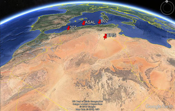
The main purpose of this research is to test the performance of the current EGNOS in Algeria without RIMS. The raw GPS data were collected by a geodetic multifrequency receiver (Trimble NetR9), which was installed on four sites located in Algeria (Figure 5) during several days in 2018, and over a time interval from 6 h to 24 h; these sites were in an area covered by EGNOS. The sampling interval was 10 s, and the elevation cut-off angle was set at 10°.
Locations of measurement sites.

The position of each site was determined by the GNSS-Lab (gLAB) software (version 5.3.0). The tool can process data from several receiver models, RINEX navigation as well as observation files and SBAS messages (Ibáñez et al., Reference Ibáñez, Rovira-García, Sanz, Juan, Gonzalez-Casado, Jimenez-Baños, López-Echazarreta and Lapin2018). EGNOS corrections data from the S120 and S123 geostationary satellites were used.
In the first step, the computation of a precise position for each site was established with differential mode; the 305 site in Oran from TYRhenian GEOdetic NETwork (TYRGEONET) is used as a reference known position. The coordinate accuracy of each site is given in Table 2.
Coordinates accuracy for each site (in metres) from Oran TYRGEONET point.

TYRGEONET is composed of 50 points distributed in the western Mediterranean area, of which two stations are in Algeria (Oran and Algiers). GPS observations were processed with Bernese 4.0 software; the coordinates, with a centimetric absolute accuracy, were expressed in the International Terrestrial Reference Frame (Kahlouche et al., Reference Kahlouche, Touam and Anzidei1998) and then transformed to WGS 84.
In the second step, analyses were performed with two computation approaches. The first processing run only used the GPS data in SPP, which is based on the code observations type, C/A code measurement in L1 frequency. The second included EGNOS differential corrections, the files containing these corrections were downloaded from the CNES Navigation and Time Monitoring Facility (NTMF) FTP server (ftp://serenad-public.cnes.fr/SERENAD0/FROM_NTMFV2/MSG/). These files are provided in the RINEX 2.11 type B format (Gurtner, Reference Gurtner2007).
4.1. Positioning accuracy
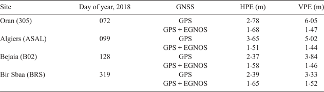
The precise position of each site is known with great accuracy, which enables us to assess the position error properly. Horizontal and vertical position errors at a defined time epoch are computed as the difference between measured position and the true position in the north, east and up components for GPS single-frequency (SPP) with and without EGNOS. Table 3 provides the comparison of position error when using EGNOS to correct the clock, ephemeris and ionospheric errors; horizontal and vertical position errors at 95% confidence levels were obtained for each site.
Horizontal position errors (HPE) and vertical position errors (VPE) using EGNOS.

It can be seen that the position accuracy of GPS with EGNOS correction is remarkably higher than GPS alone. EGNOS horizontal and vertical errors are not worse than 1·68 m (95%), whereas, in GPS alone, horizontal error could be 3·65 m (Algiers), and vertical error can exceed 6 m (Oran). Specifically, the greatest horizontal (1·68 m) and vertical position errors (1·52 m) of GPS with EGNOS were obtained in Oran and Bir Sbaa, respectively.
The improvement of vertical accuracy for GPS with EGNOS is better than for horizontal accuracy, mostly due to the better mitigation of ionospheric error as compared with GPS alone. In this respect, our results are similar to those of other studies (Zahidul et al., Reference Zahidul, Bhuiyan, Kuusniemi, Soderini, Honkala and Marila2017) which found that the vertical position error is less than the horizontal position error.
These results were obtained by correcting all SPP errors, particularly differential code biases (DCB), which can achieve 10 nano-seconds (Jin et al., Reference Jin, Jin and Li2016). Results indicate that ignoring the DCB gives the worst solution, and the positioning accuracy is better with DCB correction (Ge et al., Reference Ge, Zhou, Sun, Wang and Shi2017). In order to see improvements of GPS with and without EGNOS, positioning errors in the north, east and up components are plotted in the same figure.
For each site, Figure 6 shows the scatter plot of position errors in north and east components together (corresponding to horizontal position error) for GPS only and GPS with EGNOS. After applying EGNOS corrections, it can be seen that the points are less dispersed in GPS with EGNOS, which corresponds to smaller errors than in GPS alone.
Comparison of horizontal position error when using GPS only and GPS with EGNOS for all sites: (a) Oran, (b) Algiers, (c) Bejaia, (d) Bir Sbaa.

For all sites, we can clearly see, in Figure 6, that the east error is limited to approximately 1·5 m, while the north error is around 2 m in GPS with EGNOS. On the other hand, the east and north errors in GPS alone could be as much as 3 m and 6 m, respectively.
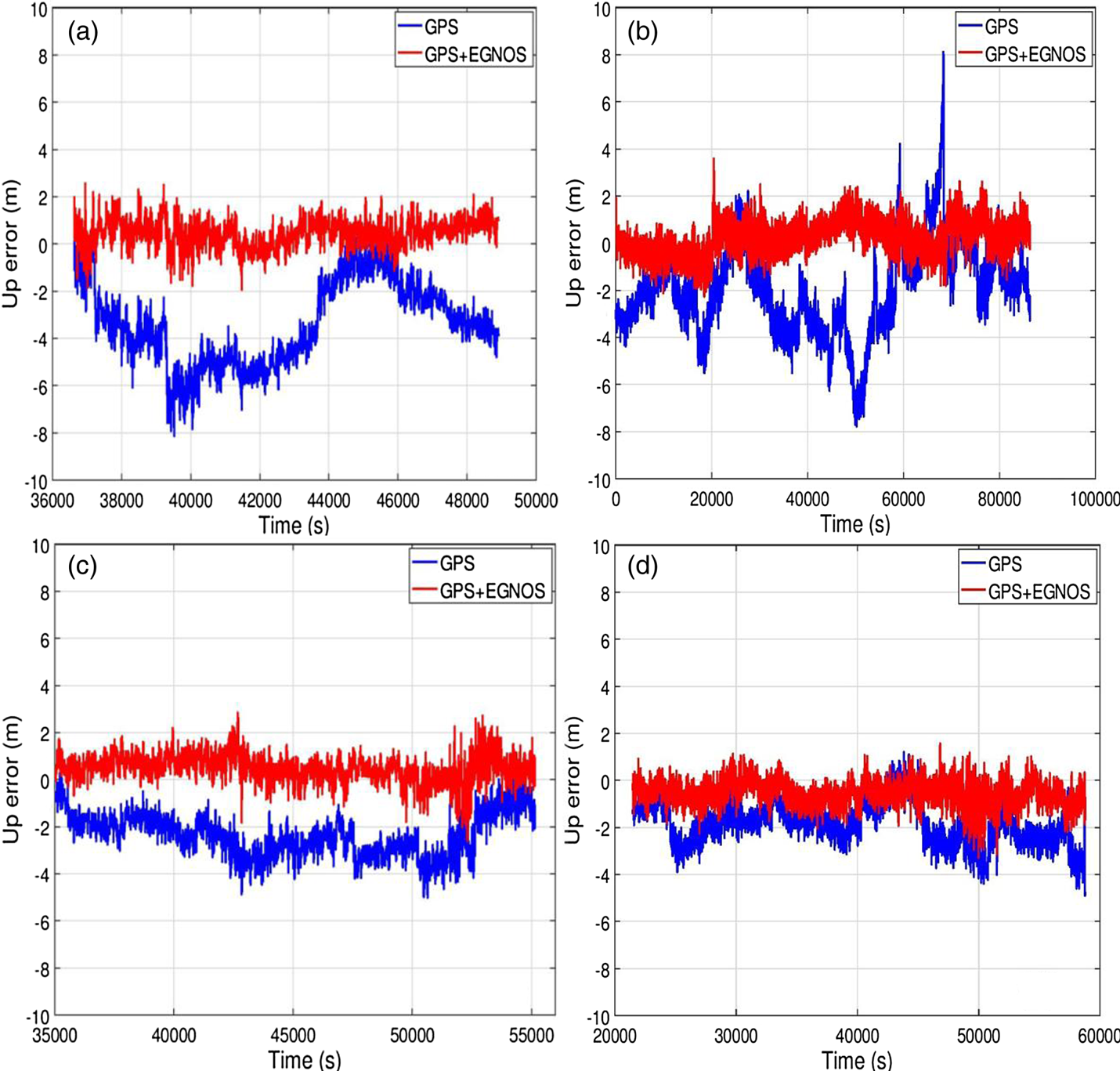
Further, in order to see improvement in the up component, we compared error before and after adding EGNOS corrections. Figure 7 shows the difference between calculated coordinates and reference known coordinates in the up component over the whole observation.
Comparison of vertical position error when using GPS only and GPS with EGNOS for all sites (a) Oran, (b) Algiers, (c) Bejaia, (d) Bir Sbaa.

For all sites, the maximum error in GPS with EGNOS is bounded between −2 and 2 m during the time of observation, whereas it is between −8 and 8 m in GPS alone. This shows again that the position accuracy is improved by applying EGNOS correction messages.
In Figures 7(b) and 7(c), there is an error peak in GPS with EGNOS at approximately 20,000 s and 43,000 s, which does not appear in GPS alone. At these epochs, some satellites have cycle-slip; after a cycle-slip, EGNOS processing needs 360 s to converge the smoothing before using the satellite again in solution computation, while in GPS only there is no need to wait for the smoothing.
To investigate the consistency of results, we analysed data from the Oran site on several dates in 2017 and 2018. The results (Figure 8) confirm that EGNOS corrections provide better accuracy performance than GPS alone. The performance of EGNOS was stable at the same level during the observations on several dates in 2017 and 2018.
Horizontal positioning errors (HPE) (a) and vertical positioning errors (VPE) (b) at Oran site.

Horizontal and vertical position errors depend on the number of GPS satellites used in position calculation and ionospheric correction. To investigate the cause of the improvement, we analysed the component of ionospheric corrections transmitted by EGNOS from all satellites used for the Algiers site, this site was observed during a 24 h period.
4.2. Corrections analysis
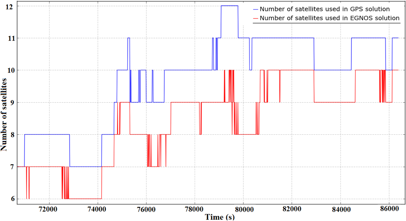
The corrections transmitted by EGNOS contribute to mitigate the ranging error sources related to satellite clocks, satellite position and ionospheric effects. EGNOS can also prevent users from receiving unhealthy satellite data which could lead to wrong positioning. Figure 9 presents the number of GPS satellites used in the solution at the Algiers site.
Number of satellites used in EGNOS solution (red) compared with number of satellites used in GPS solution (blue) at Algiers site.

Figure 9 shows the number of monitoring GPS satellites by EGNOS; it can be seen that the number of satellites used in GPS is between 7 and 12, and this number decreases in EGNOS, which means that EGNOS has eliminated some GPS satellites.
The objective of EGNOS is to take into account the status of each GPS satellite. Corrections of some satellites are not generated, however, as they are not monitored by the RIMS network, being either ‘Not Monitored’ or, where an anomaly with the satellite has been detected, flagged ‘Don't Use’. Data from such satellites will be discarded (Liu et al., Reference Liu, Chen, Chen, Kröger and Pei2012).
At the Algiers site, during a period of between 79,000 s and 80,000 s, 8–10 satellites were used by EGNOS, while 10–12 satellites were used by GPS. EGNOS eliminated some satellites needed to calculate a position, which has a direct impact on positioning accuracy; these satellites were:
– PRN9, PRN18 and PRN23: satellites flagged as ‘Not Monitored’
– PRN6, PRN7: satellites not used because the IPP was outside the IGP
– PRN32: satellite flagged as ‘Don't Use’.
These satellites are not used; this is probably caused by the lack of RIMS stations between latitude 25° and 30° in Algeria, therefore EGNOS corrections are not transmitted for satellites being tracked over the area. Consequently, corrections would be available if a RIMS station were installed in Algeria (Tabti et al., Reference Tabti, Kahlouche and Benadda2018).
Figure 10 shows the ionospheric delay provided by EGNOS when compared with GPS only (provided by Klobuchar model). The Klobuchar model corrects the ionospheric delay, which has the advantages of convenient calculation and simple structure (Su et al., Reference Su, Jin and Hoque2019). Ionospheric delay uses eight parameters, broadcast in the navigation message and typically updated once per day (Rovira-Garcia et al., Reference Rovira-Garcia, Juan, Sanz, González-Casado and Ibáñez2015). This model allows for correction of only the first order of ionosphere effect; as the higher order (second and third order) ionospheric correction on L1 frequency is centimetric (Liu et al., Reference Liu, Lia, Guoa and Lia2016), it will be neglected in this study. The ionospheric plots also show the elevation angles of satellites; the expected corrections decrease with the increase of the elevation.
Ionospheric delay for all satellites used at Algiers site.

Positioning accuracy obviously is highly dependent on EGNOS ionospheric corrections. As can be seen on almost all satellites, ionospheric correction using EGNOS is lower than the broadcast values (Klobuchar); the mean values range between 1 m and 2 m, and it can reach 8 m when the satellites are at low elevation (<5°). In GPS alone using the Klobuchar model, ionospheric correction varies mainly from about 2 m to 4 m, and it can reach 14 m when the satellites are near the horizon.
By using ionospheric corrections provided by EGNOS, it is possible to reduce ionospheric error in the pseudo range measurements. However, from Figure 10, it is not possible to confirm which of the two models (EGNOS or Klobuchar) is more accurate.
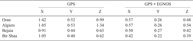
In order to reveal positioning performance, corresponding figures in three-dimensional view for each site are shown in Figure 11. It shows the coordinates determined by GPS alone and coordinates determined by GPS with EGNOS. According to these figures, it is clearly seen that positions calculated by GPS with EGNOS are less dispersed. Table 4 gives more details about the coordinate accuracy by calculating the standard deviation of the X, Y and Z coordinates for each site.
Absolute positions for each site using GPS alone (blue) and GPS with EGNOS (red) (a) Oran, (b) Algiers, (c) Bejaia, (d) Bir Sbaa.

Standard deviation (in metres).

Position accuracy was significantly improved by applying EGNOS corrections for each coordinate of all sites, mainly due to using a better ionospheric correction. The GPS-only positions are based on single-frequency measurements and the Klobuchar ionospheric model.
5. CONCLUSION
EGNOS offers improved navigation performance for an open service, in terms of precision and integrity; the performance gradually degrades as a user moves away from the service area. Our results show that there is an improvement in the three-dimensional positioning accuracy of single-frequency GPS when corrections from EGNOS are included. It is demonstrated that horizontal and vertical positioning errors of GPS with EGNOS are less than 2 m (95%), while for GPS only the errors are around 4 m in horizontal and 8 m in vertical. The results of the experiment are briefly summarised as:
– Compared with GPS only, with EGNOS the improvement of vertical accuracy is greater than the horizontal improvement using single-frequency measurements.
– The positioning accuracy is obviously highly dependent on the correction accuracy of EGNOS, which is at the metre level.
– The performance of EGNOS was at the same level during various days of the year in 2018, and the observed horizontal and vertical position errors for each site were similar.
– For the Oran site, the position error of GPS with EGNOS was stable during various days of 2017 and 2018.
Finally, we note that this improvement is obtained without any RIMS in Algeria. The implementation of RIMS in the country will permit further improvement of the corrections transmitted by the EGNOS system and real-time positioning in the area, and allow Algeria to benefit from the advantages offered by this system.
ACKNOWLEDGEMENTS
The authors acknowledge the gAGE research team from the Polytechnic University of Catalonia for the gLAB program library (available at http://www.gage.upc.edu); and would like to thank particularly Dr Deimos Ibáñez of the gAGE team for his useful help and clarifications.