I. INTRODUCTION
Recently, much work has been devoted to developing conductor/polymer composites with high dielectric constant, in which an “insulator/conductor” transition has been demonstrated, which is called the percolation effect. In this type of composites, dielectric constant (k) of the composites climbs up abruptly as the concentration of the conducting fillers approaches the neighborhood of the percolation threshold.Reference Pecharroman, Fatima and Moya1–Reference Brosseau4 The dielectric constant of these composites is much higher than the widely used ceramic/polymer composites. However, the high loss (tanδ) in these conductor/polymer composites, which is caused by the percolation tunneling current, weakens their dielectric performance. Li et al.Reference Li, Xue, Hao, Gao and Zheng5 reported that the poly (vinylidene fluoride) (PVDF) composite containing 4 vol% ester functionalized multiwall carbon nanotube (MWCNT), exhibited a dielectric constant of 400 at 1 kHz. However, its loss tangent was close to 10.
An effective way to reduce dielectric loss of the conductor/polymer composite is coating the conducting particles with a thin insulating layer to form the core@shell structure. For instance, Shen has prepared Ag@C composite particles via carbonaceous shell coating on the Ag surface. The dielectric loss of Ag@C/epoxy composite showed a low value of 0.05 at 1 kHz.Reference Shen, Lin and Nan6 Besides, as demonstrated by Xu, a low dielectric loss of 0.02 in Al@Al2O3/epoxy composites was achieved.Reference Xu and Wong7
SiO2 thin film is a commonly used insulating material with good stability. The SiO2 layer can be formed by hydrolyzing tetraethoxysilane (TEOS) on the surface of metal particles to form core@shell-structured metal@SiO2. In the past years, SiO2 encapsulated metal particles have been applied in optical and biomedical fields.Reference Gong, Liang, Huang, Chen, Jiang, Shen and Yu8, Reference Xu, Wang, Kang and Chen9 In this study, nanosized Ag particles were prepared in a solution and TEOS was hydrolyzed in situ on the particles’ surfaces to form the core@shell-structured Ag@SiO2. The Ag@SiO2 particles were used as fillers, and the mixture of BaTiO3 (BT) particles and PVDF was used as dielectric matrix. Introduction of BT to PVDF matrix could seclude the metal particles further and restrict the transportation of internal electrons and charge carriers to some extent, resulting in reduced conduction loss. Moreover, arising out of their ferroelectric properties, BT particles would generate large electric moment polarization under electric field itself, which improved the dielectric constant of the composite. The appropriate amount of BT was set as 20 vol% of the volume of the composite for all the samples.Reference Dang, Shen and Nan10
The purpose of this study was to investigate the influence of SiO2 layer and ferroelectric BT nanoparticles on the dielectric performance of the three-phase Ag@SiO2/BT/PVDF composite system. The obtained results would be helpful for understanding and development of high-performance dielectric composites with potential applications in electronic packaging and devices.
II. EXPERIMENTS
A. Materials
Silver nitrate (AgNO3, Guoyao Chemical Co. China) was used as the precursor of Ag. Hydrazine hydrate (H4N2·H2O), polyvinylpyrrolidone (PVP, Mw = 10,000 g/mol) and TEOS (all from Tianjin Damao Chemical Co. China) wereused as reducing agent, dispersant and capping agent, respectively. Poly (vinylidene fluoride) (PVDF, Shanghai 3F Co. China) was chosen as the polymer matrix. Absolute ethanol (Tianjin kaitong Chemical Co. China) was used as the solvent. Nanosized BT particles with a mean diameter of 100 nm (Guangdong Fenghua Advanced Techlology Co. China) were used as the ceramic fillers.
B. Preparation of Ag nanoparticles
400 mL (0.0147 mol/L) AgNO3 solution was added into a 1000 mL three-neck flask, followed by addition of 50 mL (0.0006 mol/L) PVP solution via mechanical agitation (750 rpm), and then 100 mL (0.2355 mol /L) H4N2·H2O solution was dropped into the above mixture, the reaction was kept for 40 min. Finally, the fresh Ag suspension was obtained, and then was rinsed and centrifuged three times with ethanol solution (the volume ratio of ethanol to water was 6:1). At last, the obtained Ag nanoparticles were dried in a vacuum oven at 80 °C for 24 h.
C. Preparation of Ag@SiO2 nanoparticles
100 mL absolute ethanol was mixed with the fresh Ag suspension, followed by the addition of 1 mL TEOS, and the reaction was kept for another 6 h. The Ag@SiO2 suspension was finally obtained. The suspension was centrifuged and rinsed with ethanol solution. At last, the resulting Ag@SiO2 nanoparticles were dried in a vacuum oven at 80 °C for 24 h.
D. Determination of density of Ag@SiO2 nanoparticles
M1 g Ag@SiO2 and M2 g PVDF were dispersed into some ethanol with ultrasonication treatment with 200 W in power- and mechanical stirring with 200 rpm for 30 min, respectively. Then the two well-dispersed suspensions were mixed with each other completely under ultrasonication and mechanical stirring with 400 rpm for 3 h. The obtained slurry was placed in a vacuum oven at 80 °C for 24 h to evaporate the residual ethanol absolutely. Finally, the mixed powders were hot-molded into disk-like sample at 200 °C and 1 MPa for 30 min. The whole volume Vt of the sample was measured and calculated. The density of PVDF was denoted as ρ2, and the density of Ag@SiO2 (ρ1) could be calculated from the equation as follow:  , through which the volume fraction of the Ag@SiO2 in the composite could be derived.
E. Synthesis of the three-phase Ag@SiO2/BT/PVDF composites
The preparation of the composite samples containing appropriate amounts of PVDF, Ag@SiO2 and BT particles followed the same process as described in Sec. II.E. The finally obtained disk-shaped samples have a diameter of 12 mm and a thickness of 1 mm. To test the dielectric properties, conductive silver paste was painted on both sides of the samples as electrodes. For comparison, the three-phase Ag/BT/PVDF composites were prepared in the same way.
F. Characterization of the three-phase Ag@SiO2/BT/PVDF and Ag/BT/PVDF composites
The phase constituent of the Ag@SiO2 particles was examined using an x-ray diffractometer (XRD, D/max-2500/PC, Rigaku Co.) with Cu Kα radiation (λ∼0.154 nm) and 40 kV of acceleration voltage applied. The morphology of the Ag@SiO2 particles was investigated with scanning electron microscope (FE-SEM, HITACHI S-4800). The micrograph of Ag@SiO2 particles was further examined using a transmission electron microscope (TEM) of JEM-2100 (HR) with acceleration voltage of 200 kV. Dielectric and electrical properties of the two composites were measured with high precision impedance analyzer of Agilent 4294A with a polarization voltage of 500 mV in a frequency range of 100 Hz to 10 MHz. Effects of temperature on dielectric properties of the three-phase Ag@SiO2/BT/PVDF composites were investigated via Agilent 4294A impedance analyzer with a THMS 600 Temperature Controlled stage (Linkam Scientific Instruments) and a T95-LinkPad Temperature programmer (Linkam Scientific Instruments) in a temperature range between 30 °C and 160 °C.
III. RESULTS AND DISCUSSION
A. Formation of Ag@SiO2 particles
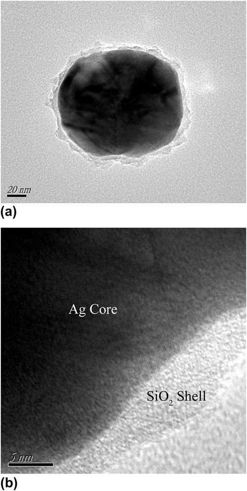
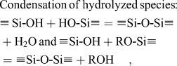
Figure 1 presents TEM images of Ag particle treated with TEOS, which shows a clear core@shell structure, and the gray SiO2 shell is formed on the surface of the dark Ag core. Figure 1(a) shows that the thickness of SiO2 shell is about 10 nm. The crystal lattice can be observed in the Ag core area while the SiO2 shell is amorphous, as illustrated in Fig. 1(b). The following schematic illustration and formulas present the formation mechanism of SiO2 layer. The coupling agent PVP is first absorbed on the Ag surface, which stabilizes the Ag nanoparticles in water and ethanol so as to improve the affinity of SiO2 to the surface of Ag. Then, SiO2 layer is formed and grows through the hydrolysis and condensation of TEOS on the Ag surface by process (1) and (2)Reference Graf, Vossen, Imhof and Blaaderen11:


TEM (a) and HR-TEM (b) pictures of Ag@SiO2 nanoparticle.
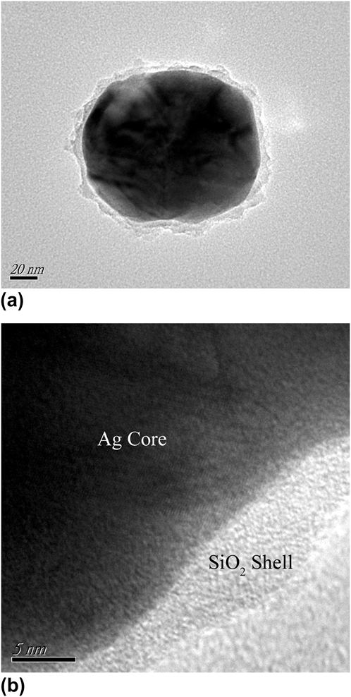
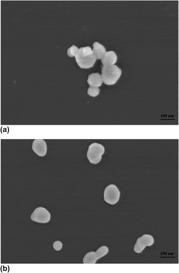
Figure 2 shows SEM images of Ag@SiO2 and Ag nanoparticles. As shown in Fig. 2(a), the Ag@SiO2 nanoparticles are subspheroidal and the size range of these particles is between 50 nm to 150 nm, which corresponds to that illustrated in Fig. 1. Besides, compared with Ag nanoparticles shown in Fig. 2(b), the surface of Ag@SiO2 nanoparticles looks much coarser, which further confirms the existence of SiO2 layer on the Ag surface.
SEM images of (a) Ag@SiO2 and (b) Ag nanoparticles.

B. Crystal and microstructure of the three-phase Ag@SiO2/BT/PVDF composites
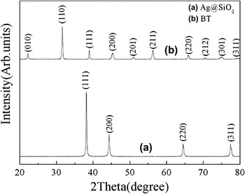
Figure 3 presents XRD spectrum of Ag@SiO2 and nanosized BT particles. The four strong peaks at 2θ = 39.1°, 45.3°, 65.7° and 78.8° correspond to the (111), (200), (220), (311) of the typical cubic Ag phase, respectively. No SiO2 phase is detected, which implies that the SiO2 layer is amorphous or the diffraction from the SiO2 thin layer is weak and overwhelmed by that of Ag cores. It is noticed that the nanosized BT particles mainly exhibit a cubic phase, which is consistent with an earlier report that as the grain size of BT decreased to or below 0.7 μm, the cubic symmetry structure tends to form in BT.Reference Arlt, Hennings and Dewith12
XRD spectrum of Ag@SiO2 and nanosized BT particles.

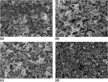
Figure 4 presents the SEM cross-section images of the three-phase Ag@SiO2/BT/PVDF composites. As shown in the figure, the distribution of Ag@SiO2 and nanosized BT particles in PVDF becomes less homogeneous with increase in Ag@SiO2 content. Especially, when the Ag@SiO2 content reaches 45 vol%, almost no fiber PVDF matrix can be observed. The reason is that as the percentage of PVDF becomes less, it cannot fill up the space between fillers completely. As a result, the agglomeration of fillers and voids (or pores) in the composites are inevitable, as shown in Fig. 4(d).
SEM cross-section images of the three-phase Ag@SiO2/BT/PVDF composites with Ag@SiO2 volume fraction of (a) 0 vol%, (b) 35 vol%, (c) 40 vol% and (d) 45 vol%, BT of 20 vol% in all cases.

C. Dielectric properties
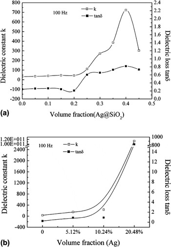
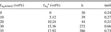
Figure 5 presents the dielectric constant k and loss tanδ of the three-phase Ag@SiO2/BT/PVDF and Ag/BT/PVDF composites as a function of Ag@SiO2 and Ag volume fraction at 100 Hz, respectively.
Dielectric constant and loss of (a) the three-phase Ag@SiO2/BT/PVDF versus volume fraction of Ag@SiO2 and (b) Ag/BT/PVDF composites versus volume fraction of Ag, respectively.

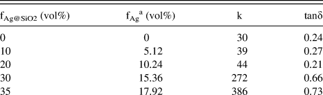
As shown in Fig. 5(a), when Ag@SiO2 content is between 0 vol% and 20 vol%, the values of k change smoothly with Ag@SiO2 content, which are 30 and 44 at 0 vol% and 20 vol%, respectively. The small increase of value of dielectric constant k is mainly attributed to the interfacial polarization or Maxwell-Wagner-Sillars (MWS) effectReference Maxwell13–Reference Sillars15 induced by addition of Ag@SiO2 nanoparticles. It could also be interpreted through percolation theory to a certain extent. The SiO2 layer and Ag core act as a part of matrix and conductive filler, respectively, and the value of dielectric constant k would increase modestly at low filler loadings as demonstrated by the percolation theory.Reference Nan16 When Ag@SiO2 content exceeds 20 vol%, the value of dielectric constant k of the composites increases prominently and achieves a maximum value of 723 at 40 vol% Ag@SiO2. This phenomenon can be understood in terms of the microcapacitor network. When Ag@SiO2 content is increased to 40 vol%, the Ag content in the composite reaches a high value of 20.48 vol%, as presented in Table I, which is higher than the theoretical critical value of 16 vol% in the reported percolative composite.Reference Nan16 The high “threshold” value of “Ag” content could be attributed to the insulating SiO2 layer around Ag. In this case, Ag cores act as electrode of the microcapacitor network and SiO2 layer serves as a part of matrix. The area of electrode grows remarkably but the distance between electrodes reduces with the increase of Ag@SiO2 content, which leads to the formation of large microcapacitor network and thus yields the significant enhancement of the value of dielectric constant k. Besides, large interfaces between Ag and matrix are introduced by high Ag@SiO2 loading. And the permittivity and conductivity for the conducting Ag and insulating matrix are significantly different. As a result, a large number of charge carriers accumulate on these interfaces and strong MWS effect has been developed, which plays an important pole in the enhancement of value of dielectric constant k of the composite. Further, the addition of ferroelectric BT nanoparticles to the PVDF matrix not only induces interfacial polarization but also produces large electric moment polarization under applied electric field, which enhances the dielectric properties of the three-phase system. However, it is worth noting that when Ag@SiO2 content is beyond 40 vol%, the value of dielectric constant k decreases. For example, it reduces to 303 at 45 vol% Ag@SiO2, as shown in Fig. 5(a). The reason should be attributed to the inhomogeneous distribution of fillers and the voids induced by high inclusion concentration, as depicted in Fig. 4(d). The pores are filled with air with the dielectric constant of approximately 1, and they would receive a concentrated electric field and prevent from applying electric field to BT and Ag@SiO2 fillers. As a result, only a limited dielectric polarization in fillers seems to have been attributed to the improvement of dielectric constant of the composite,Reference Kakimoto, Furuhashi, Ogawa and Aki17 leading to the decrease of the effective dielectric constant. Figure 5(a) also shows that variation of tanδ of the composite is smooth with Ag@SiO2 content, which is similar to that of value of dielectric constant k before 20 vol%. A large increase in dielectric loss is observed as the Ag@SiO2 content reaches 20 vol%, and tanδ achieves a maximum value of 0.82 at 40 vol% Ag@SiO2. However, the dielectric loss of the composite does not grow further when Ag@SiO2 content continues to increase. For instance, the tanδ is 0.73 at 45 vol% Ag@SiO2, which implies that no typical percolation effect is found in such composites. The reason could be that the insulating SiO2 layer on the surface of Ag prevents Ag cores from connecting with each other and thus restricts the transportation of internal electrons between Ag cores under applied electric field. As a result, the conduction loss is suppressed and does not rise significantly with Ag@SiO2 content. The BT particles around Ag@SiO2 also serve as a barrier of electron transportation and seclude Ag@SiO2 particles to some degree, which contributes to the improvement of the dielectric properties of the composite significantly.
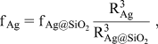 RAg≈40 nm, RAg@SiO2 ≈ 50 nm, and the values of RAg and RAg@SiO2 could be determined from
In contrast, for the three-phase Ag/BT/PVDF composites, both dielectric constant and loss gradually increase with Ag content before it reaches a percolation concentration, as presented in Fig. 5(b). The dielectric constant is no more than 240 when Ag content is less than 10.24 vol%. When Ag concentration is close to 20.48 vol%, both values of the dielectric constant k and the loss tanδ increase dramatically. Tanδ increases from 1 at 10.24 vol% to more than 800 at 20.48%, indicating the occurrence of percolation, which is caused by the formation of conducting network through Ag particles without insulating layer between them.
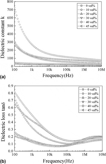
Figure 6 presents the dependence of the dielectric constant k and the loss tanδ of the three-phase Ag@SiO2/BT/PVDF composites on frequency. As shown in Fig. 6(a), value of dielectric constant k is nearly independent on the whole measured frequency range when Ag@SiO2 content is below 30 vol%, and it keeps a nearly constant value of 30 and 44 for the composites with 0 vol% and 20 vol% Ag@SiO2, respectively. For the composites containing Ag@SiO2 of 30 vol% or above, the value of dielectric constant k drops remarkably in the frequency range of 100 ∼ 10 kHz. It reduces from 723 (100 Hz) to 150 (10 kHz) for the composite containing 40 vol% Ag@SiO2. The results indicate that the dielectric property is determined by BT/PVDF matrix as the filler concentration is low. As the Ag@SiO2 loading is increased, the effect of Ag@SiO2 particles on the dielectric behavior of the composites becomes prominent. Additionally, the noticeable drop of dielectric constant with increasing frequency is associated with the interfacial polarization generated by inclusions. The enhancement of value of the dielectric constant induced by interfacial polarization can be attributed to the MWS effect.Reference Maxwell13–Reference Sillars15
The dependence of dielectric constant (a) and loss (b) of the three-phase Ag@SiO2/BT/PVDF composites with 20 vol% of BT and various amount of Ag@SiO2 on frequency.

The tanδ versus frequency shows a similar tendency similar to that of the dielectric constant k, as shown in Fig. 6(b). For the composites with the Ag@SiO2 content less than 30 vol%, the tanδ follows the same behavior of the two-phase BT/PVDF. When the Ag@SiO2 content reaches 30 vol% or above, the tanδ is strongly dependent on frequency at low frequencies. A large tanδ of 0.82 for 40 vol% at 100 Hz is observed in Fig. 6(b), which was assigned to the leakage loss at approximately direct current field, which is associated with the large dielectric constant observed in Fig. 6(a) at low frequencies, meaning that a large portion of the electric field displacement vector is viscous loss. When the frequency is above 100 kHz, the tanδ of all composites exhibits weak frequency dependence. The small peak at 6 MHz was due to the relaxation process of PVDF matrix, which was caused by the reorientation of electric moment of ferroelectric polymer PVDF under alternating current field.
MWS effect is a relaxation process appearing in heterogeneous systems that are made up of different phase constituents with different permittivities and resistivities. In this case, charge carriers will be accumulated on interfaces of the system under applied electric field and thus interfacial polarization occurs. The relaxation process happens at lower frequencies and is very sensitive to frequency, consequently, leading to strong dependence of dielectric response on frequency.Reference Maxwell13–Reference Sillars15 However, with the insulating SiO2 shell layer on the Ag core surface, the MWS charges have localized motion but appear to be better confined by the silica coating and do not contribute toward a percolative DC conductance loss.
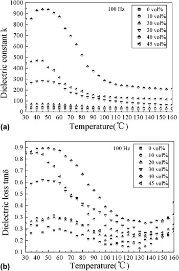
Figure 7 presents the temperature dependence of the dielectric constant k and loss tanδ of the three-phase Ag@SiO2/BT/PVDF composites measured at 100 Hz. As shown in the Fig. 7, there is a relaxation peak around 50 °C for both k and tanδ in all samples, and becomes sharper with the increase of Ag@SiO2. The reason is that the high filler concentration is likely to destroy the crystallinity and lead to formation of the amorphous area in PVDF matrix during the hot-pressing process. In this case, extrinsic carriers’ mobility would increase in the amorphous region and thus form the manifestation of more space charges, which produces the intensive relaxation process.Reference Kochervinskii, Malyshkina, Gavrilova, Sulyanov and Bessonova18
The effects of temperature on dielectric constant (a) and loss (b) of the three-phase Ag@SiO2/BT/PVDF composites with 20 vol% of BT and various amount of Ag@SiO2 measured at 100 Hz.

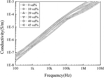
Figure 8 presents the conductivity of the three-phase Ag@SiO2/BT/PVDF composites versus frequency. The conductivity of the composites grows up over the whole range of measured frequency. Nevertheless, the conductivity is below 10−7 S/m even at a high concentration of 45 vol% at 100 Hz and is far less than the reported 10−3 S/m for 25 vol% Ni-filled PVDF matrix composite.Reference Dang, Lin and Nan19 The relatively low conductivity further testified that the SiO2 layer acted as an internal electron barrier layer, which restricted movement of electrons and avoided large leakage current. In addition, BT nanoparticles around Ag@SiO2 also made important contributions to maintaining the low conductivity, and it was in good correspondence to the dielectric behavior as described in Fig. 5(a).
Conductivity of the three-phase Ag@SiO2/BT/PVDF composites with 20 vol% of BT and various amount of Ag@SiO2 versus frequency.

D. Discussion on the effects of SiO2 layer
Recently, much research interest has been directed to investigate the conductor/polymer percolative composite systems. However, the high conduction loss appearing at the percolation threshold is always an important limitation for the practical application of the materials. As reported by the foregoing statement,Reference Li, Xue, Hao, Gao and Zheng5 the loss tangent could reach 1000 in stainless steel fibers filled PVDF matrix composite with 10 vol% of the fiber at 50 Hz. The ultra high loss is produced by the formation of conductive pathway when conducting inclusion concentration is in the neighborhood of percolation threshold, where the composite system transforms from an insulator to a conductor.Reference Nan16 As is known, SiO2 is an excellent insulator with good stability and can be synthesized through a simple hydrolysis and condensation of TEOS. In this study SiO2 was formed on the Ag surface as the insulating layer to encapsulate Ag and prevent Ag particles from contacting with each other at high Ag loading, which restricted the transportation of internal electrons between Ag particles. As a result, it was very difficult to form conducting network even when the Ag concentration was high and thus conduction loss could be kept at a relatively low level. For instance, when the Ag content was increased to 20.48 vol%, which is higher than the theoretical percolation threshold of 16 vol%, a high dielectric constant of 723 was obtained and the tanδ was 0.82, as shown in Table I. The tanδ value is much lower compared with the composite containing Ag particles without encapsulating, which is as high as 800 at the same filling level of Ag, as shown in Fig. 5(b). A strong dependence of the dielectric properties on frequency was observed in the Ag@SiO2 filled composite system, which could be attributed to the interfacial space charges associated with the MWS effect. However, due to the existence of the insulating SiO2 layer around Ag core, the MWS charges have been confined and their long-path motion was suppressed. As a result, the typical percolative conduction, or the “insulator to conductor” transition, has not occurred even at a high Ag@SiO2 fillers loading.
This work provides an efficient way to acquire a composite with high dielectric constant and suppressed conduction and dielectric loss. The influence of the thickness of SiO2 layer on dielectric properties and breakdown strength of the three-phase composite will be discussed and analyzed in detail in our future work. Further, PVDF matrix possesses high value for dielectric constant k, which is based on its ferroelectric nature,Reference Sun, Li, Zhang and Zhong20 but it is easily subjected to frequency and temperature, and has a high dielectric loss itself. Therefore, polymers with low loss and good stability can beused as dielectric matrix, such as epoxy, polyimide and so on. The future objective is to improve the whole dielectric properties of such three-phase composites for practical applications.
IV. CONCLUSIONS
As per details described in this paper, Ag nanoparticles were prepared through a simple wet chemical reduction process and modified with TEOS to form the core-shell structured Ag@SiO2. The dielectric behavior of the three-phase Ag@SiO2/BT/PVDF composites has been investigated. The typical percolation of the conductor/polymer system was not observed in the three-phase composite, which originated from the SiO2 layer acting as an internal electron barrier and restricted electrons from transferring between Ag cores. And BT particles further isolated Ag@SiO2 particles. The maximum dielectric constant value of 723 with the loss of 0.82 at 100 Hz was obtained at 40 vol% Ag@SiO2 and 20 vol% BT. The high dielectric constant of the composite was owing to the formation of microcapacitor network and strong MWS effect caused by high Ag@SiO2 concentration and high k matrix. Additionally, it was noticed that the ferroelectric polymer PVDF with a high loss contributed to the loss of the composite. Thus, to further lower the loss of such three-phase composite, polymers with low loss and excellent stability such as epoxy and polyimide, would be promising matrices used in the composite system for practical applications.
ACKNOWLEDGMENTS
This work was financially supported by National Natural Science Foundation of China (Nos. 50807038 and 20971089), the research funding from National S&T Major Project with the Contract No. 2009ZX02038 and Shenzhen fundamental research project (No. JC200903160423A).