Introduction
With the rapid development of the modern wireless communication field, the requirements of miniaturization, dual-band, and integration are becoming more and more common. In traditional wireless systems, antennas and filters are designed separately, which leads to large system size and loss. Therefore, the integrated design of two separate devices becomes popular. Currently, the most popular research method is to replace the last stage of the filter with a microstrip antenna or a direct cascade. Although this method reduces the size, it also has some problems, such as a single operating band [Reference Juma’a, Al-Mayoof, Abdulhameed, Alnahwi, Al-Yasir and Abd-Alhameed1, Reference Patel, Tomar and Parihar2], realizing dual bands with low gain [Reference Yang, Yang, Sun and Hu3–Reference Deng, Tan, Hou, Sun and Guo5], and narrow bandwidth [Reference Cui, Zhang, Wu and Yan6]. The resonator with step impedance resonator (SIR) structure [Reference Li, Zhao, Tang and Yin7] is suitable for designing dual-band devices with flexible and simple structures. Therefore, there is a large number of research in microwave device design, and dual-band filtering antennas based on SIR have been further studied. For example, we can utilize the SIR structure and aperture-coupled feed patch technology to integrate the two into a dual-band filtering patch antenna, but with lower gain [Reference Cui, Zhang and Yan8]. The novel structure is utilized to introduce a pair of SIR resonators in the feed network. The loaded resonators can flexibly control the center frequency of the two bands, and cooperate with the ring slot antenna to design the filter antenna. However, the size is large [Reference Adhikary, Sarkar, Sharma, Biswas and Akhtar9].
To solve the problems of small gain, large size, and high system loss, this paper designs a dual-band monopole filtering patch antenna based on the SIR branch shunt structure. The antenna is integrated on a double-layer substrate with a coupled probe feed design. The dual-band characteristics of the antenna are realized by changing the natural pattern of rectangular patch such as TM10 and TM01 patterns by feeding. It can operate in both ISM and WLAN (2.4 GHz) bands and can flexibly control the center frequency of both bands. The antenna has good performance and small size, as well as good filtering identity and stable radiation features. It realizes dual-band characteristics. When it compares with existing multiple dual-band antennas, it has flexible design and simple structure.
Structural design of multimode based on SIR shunt branch
Structural design of multimode resonators
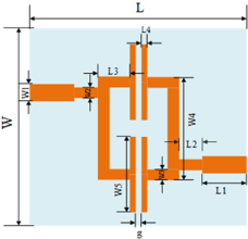
The SIR-based multimode resonator model is shown in Fig. 1. It designs the branching shunt structure at the end of the resonator. The purpose of bending the microstrip line is to reduce the circuit size and to form a dual-frequency filter through electrical coupling.
Dual-passband filter model [Reference Li, Zhao, Tang and Yin7].

The resonator is based on SIR shunt design at the end of the two open-circuit branches. This can form two symmetrically loaded parallel open-circuit branches and realize a dual-passband filter response by cascading the two sections. Since the structure is symmetrical, we can analyze the resonance characteristics of the filter through the odd-even mode analysis method [Reference Pozar, Zhang, Zhou and Wu10].
The theories of resonator transmission line are as follow:
 \begin{equation}\begin{array}{*{20}{l}}
{{Y_{{\text{in-odd}}}} = j{Y_2}{\text{tan}}{\theta _2} + j{Y_3}{\text{tan}}{\theta _3} - j{Y_1}{\text{cot}}{\theta _1}}
\end{array}\end{equation}
 \begin{equation}{Y_{{\text{in-even}}}} = j{Y_2}{\text{tan}}{\theta _2} + j{Y_3}{\text{tan}}{\theta _3} + j{Y_1}{\text{cot}}{\theta _1}\end{equation}
where Y in-odd and Y in-even are the input conductances of the odd-mode and even-mode equivalent circuits; θ 1, θ 2, and θ 3 are the electrical lengths of the transmission line; Y 1, Y 2, and Y 3 are the conductances of the transmission line. When Y in-odd and Y in-even are equal to zero, the odd-mode and even-mode resonance conditions of the resonator are as follows:
 \begin{equation}j{Y_2}{\text{tan}}{\theta _2} + j{Y_3}{\text{tan}}{\theta _3} - j{Y_1}{\text{cot}}{\theta _1} = 0\end{equation}
 \begin{equation}j{Y_2}{\text{tan}}{\theta _2} + j{Y_3}{\text{tan}}{\theta _3} + j{Y_1}{\text{cot}}{\theta _1} = 0.\end{equation}
From formulas (3) and (4), it can be concluded that when θ 3 equals θ 2, Y 3 equals Y 2, the resonant frequencies of the two modes are determined by the ratio of the electric length θ 1 to θ 2 and the ratio of Y 2 to Y. For the SIR shown in Fig. 2, the ratio of the second resonant frequency to the first resonant frequency may be determined by the resonant condition of the resonator:
 \begin{equation}{R_{\text{z}}}\tan {\theta _1} + \tan {\theta _2} = 0\end{equation}
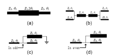
Filter equivalent structure and transmission line model. (a) Transmission line model, (b) equivalent structure, (c) odd model equivalent circuit, and (d) even model equivalent circuit [Reference Li, Zhao, Tang and Yin7].

where R z = Z 1/Z 2 is the impedance ratio. The center frequency is f 1 (2.45 GHz), and the second resonant frequency is f 2 (5.8 GHz). To simplify the calculation, we use the equivalent length in the design process. The resonant frequency is expressed as:
 \begin{equation}\theta (\,{f_1}) = \tan \sqrt {{R_z}} \theta ({f_2}).\end{equation}
We can obtain:
 \begin{equation}{f_2}/{f_1} = {\text{arc}}\tan \sqrt {{R_z}} .\end{equation}
According to the transmission line theory, we can obtain the transmission line model shown in Fig. 2(a) and the equivalent structure shown in Fig. 2(b). Figure 2(c) and (d) are odd mode equivalent circuit and even mode equivalent circuit.
Resonator parameters analysis
The final structural dimensions of the dual-pass filter are determined by simulating and analyzing the key parameters. We adopt the method of control variables to analyze the influence of relevant parameters on the filter performance. In this section, we analyze the variation of S-parameters when the length W5 and width L4 take different values. By this method, we can obtain the optimal values.
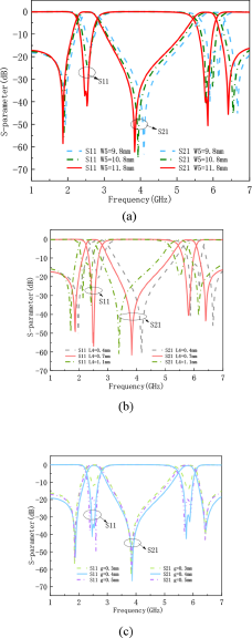
Figure 3(a) shows the effect of W5 on the performance of the filter S-parameters at different lengths when L4 is 0.7 mm. As W5 increases from 9.8 mm to 11.8 mm, there is an effect on both frequency bands. As the center frequency moves to the high frequency, the effect on the high frequency is relatively larger. Figure 3(b) shows the effect of L4 on the S-parameter performance at different widths when W5 is 11.8 mm. When L4 is increased from 0.4 mm to 1.1 mm, the center frequency shifts toward the low frequency as a whole. The performance of the two passbands is affected, and the bandwidth is gradually narrowed. There are 7% in the low frequency and 10% in the high frequency. Based on the overall consideration, W5 is chosen to be 11.8 mm and L4 is chosen to be 0.7 mm. Figure 3(c) shows the effect of the coupling gap g parameter between the two resonators on the filter performance. When g = 0.3 mm, the filter bandwidth is narrow, the return loss coefficient is large, and the filter performance is poor. As the g parameter increases, the coupling gap of the resonator gradually increases, and the reflection coefficient of the filter shows a tendency to decrease and then increase. At the same time, the bandwidth also tends to widen, and the filtering performance is significantly improved. Therefore, based on the comprehensive consideration, the final value of the coupling gap g parameter is 0.4 mm.
Simulation curves of S parameters corresponding to different values of each parameter.

From the above simulation results, it is clear that the parallel branch has a significant effect on the center frequency and bandwidth performance of the filter, which reflects that its design is flexible. In addition, it increases the adjustable parameters. Therefore, this paper obtains the suitable dual-passband characteristics by tuning W5 and L4.
Design of dual-frequency patch filtering antenna
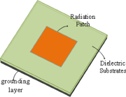
The structure of the microstrip antenna is shown in Fig. 4. It consists of a ground plane, a dielectric substrate, and a radiating patch. The dual-frequency characteristics of the antenna are realized by changing the pattern of rectangular patches such as TM10 and TM01.
Schematic diagram of the basic structure of a microstrip antenna.

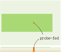
The microstrip patch antennas in this section are coaxial probe-fed. The feed method is shown in the Fig. 5. The outer conductor of the coaxial line is connected to the metal floor of the antenna and the inner conductor is connected to the patch. This approach optimizes impedance matching by adjusting the position of the feed point.
The feed method patch antenna.

For a rectangular microstrip patch antenna with a single feed point, its length and width correspond to two different resonant frequencies. If we choose a suitable feed location, the patch antenna can excite two different frequency bands, thus realizing the dual-band characteristics of the antenna. To facilitate the design and reduce the design variables, the position of the bottom filter structure is fixed during the antenna design process. This can study the effect of patch position and probe feed position on the antenna design.
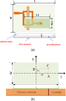
The structure of the double-layer filter antenna is shown in Fig. 6(a). The filter antenna can be viewed as a three-layer structure. The bottom layer is a dual-frequency filter resonator structure, the middle layer is a grounding layer, and the upper dielectric substrate surface is a radiating patch. The dielectric substrate sheet in the lower layer is the same as the filter structure. The dielectric plate is made of Rogers RO4003 (tm) with a dielectric constant of 3.55 and a loss tangent of 0.0027. The dielectric substrate in the upper layer is FR4 sheet with a thickness of 1.6 mm (h1), the relative permittivity and loss tangent are 4.4 and 0.02. The overall dimensions are 35 mm × 45 mm × 2.4 mm3, and the wavelength of 2.45 GHz is λ g. Then the relative dimensions are 0.29λ g × 0.37λ g. The proper feed position can stimulate the multi-band characteristics of the patch antenna. In Fig. 6(b), it is fed at the 50 Ω feed positions (points A and B) in the X- and Y-axis directions at the center position. This excites the TM10 and TM01 modes of the radiating patch without causing interference from other modes. Therefore, selecting point C excites the two resonant modes of the radiating patch. These two resonant modes correspond to two resonant frequencies, thus realizing the dual-band operating characteristics of the radiating patch.
Schematic diagram of dual-frequency filter patch antenna structure based on probe feeding. (a) Schematic diagram of double-layer. (b) Schematic diagram of coaxial feeding of microstrip filter antenna structure patch.

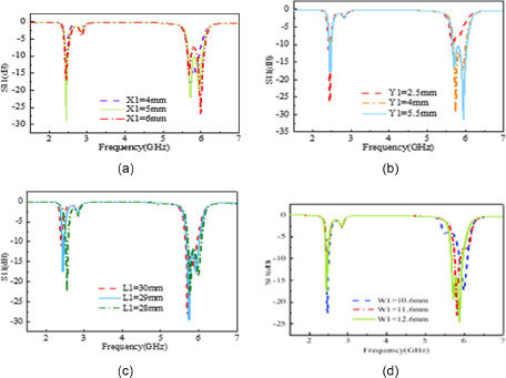
X1 and Y1 are the vertical and horizontal distances between the patch center point and the probe position, which are the key factors affecting the resonant frequency of the patch antenna. Figure 7(a) and (b) show the effect of X1 and Y1 on the S-parameter performance of the filtering antenna. The variation of X1 and Y1 affects the TM10 and TM01 modes of the radiating patch. Thus they correspond to the low- and high-frequency performance of the patch antenna. This is consistent with the idea that the two resonant frequencies correspond to the length and width of the radiating patch. Figure 7(c) and (d) show the effect of variation in the radiating patch’s length and width on the filter antenna’s resonant frequencies. The variation in the length of the radiating patch determines the variation of the low-frequency resonant frequency. We can flexibly control the low-frequency resonant frequency by adjusting the length of patch L1. However, this has little effect on the high frequency. Similarly, the width of the radiating patch corresponds to the high-frequency operating frequency point. It has little effect on the low frequency. The filtering antenna performs best when X1 = 5 mm, Y1 = 4 mm, L1 = 29 mm, and W1 = 11.6 mm.
Effect of (a) X1, (b) Y1, (c) L1, and (d) W1 on the S-parameter performance of patch filter antennas.

Simulation and testing
Simulation and test results of the dual-passband filter
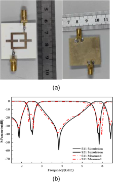
Based on the above simulation analysis, the final dimensions are W = 35 mm, W1 = 1.8 mm, W2 = 1.2 mm, W3 = 2.2 mm, W4 = 15.4 mm, W5 = 11.8 mm, L = 29.8 mm, L1 = 5 mm, L2 = 3 mm, L3 = 6 mm, L4 = 0.7 mm, g = 0.4 mm, h = 0.8 mm; the overall dimensions are 35 × 29.8 × 0.8 mm3, as shown in Fig. 8(a).
Comparison of simulated and tested S-parameters of dual-passband filters.

Finally, the center frequency points of the high and low bands are 5.8 GHz and 2.45 GHz. The relative bandwidths of S11 less than −10 dB are 6% (5.6–5.95 GHz) and 12.5% (2.35–2.65 GHz). The insertion losses at the center frequency are 0.14 dB and 0.3 dB, and the minimum reflection coefficients are −41.8 dB and −50.5 dB. The passband of the filter covers the ISM radio band and the 2.4 GHz band for WLAN. It supports multi-band operation. A comparison of the test results with the simulation results is shown in Fig. 8(b). The center frequency of the low band is 2.43 GHz and the center frequency of the high band is 5.86 GHz. The bandwidths are 350 MHz (2.3–2.65 GHz) and 400 MHz (5.65–6.05 GHz) with the relative bandwidths of 14.3% and 6.9% when the S11 is less than −10 dB. The insertion losses are 0.55 dB and 1.69 dB for the two bands, and the minimum reflection coefficients in the passband are −33.38 dB and −40.88 dB.
The tested dual-band characteristics meet the design requirement and the bandwidth covers the target band with excellent out-of-band rejection. However, there is a slight increase in insertion loss compared to the simulation results. Both bands have a slight frequency shift at the center frequency point. The reflection coefficient performance, high frequency band out-of-band transmission zero performance, and steepness characteristics are slightly worse than the simulation results. Considering factors such as processing accuracy and inlet port welding, the error results are within acceptable limit and the overall test results are consistent.
Simulation and test results of dual-band patch filter antennas
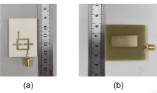
From the analysis in the previous section, we determined the final dimensions of the filter antenna: L = 45 mm, W = 35 mm, L1 = 29 mm, and W1 = 11.6 mm. Figure 9 shows the actual processed image of the dual-band filtering patch antenna. The filter is on the front and the antenna is on the back.
Front (a) and back (b) of dual-band filter patch antenna.

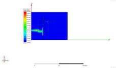
For a deeper understanding of the antenna radiation characteristics, Fig. 10 shows the surface current distribution of the antenna at the resonant frequency.
Surface current distribution of the antenna.

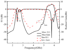
Figure 11 shows the tested S11 parameters and gain curves compared to the simulated parameters. The low-band S11 parameters are the same, with a slight frequency deviation in the high-frequency band, but the bandwidth covers the simulation results. The relative bandwidths of the 2.45 GHz band are 3.3% (2.41–2.49 GHz) and 7.8% (5.45–5.95 GHz) at S11 less than −10 dB. The simulated and tested gain curves are also consistent. The impedance matching is slightly different in the lower frequency band. The frequency operating bandwidth is narrow and the gain is low, but in the two frequency bands also obtained gains of 1.71 dBi and 6.25 dBi.
Comparison of S11 parameters and gain curves for simulation and testing of dual-frequency filter patch antennas.

Due to the introduction of the filter structure, the gain curve produces four gain zeros at 2.08 GHz, 3.54 GHz, 4.81 GHz, and 6.41 GHz. The rejection level between the two passbands exceeds 30 dBi. The low band out-of-band rejection is less than −30 dBi. The high band out-of-band rejection is less than −20 dBi, which achieves high band selectivity and good filtering characteristics.
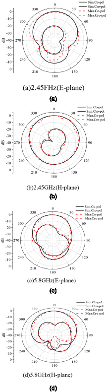
Figure 12 shows the normalized radiation pattern for simulation and test comparison in the 2.45 GHz and 5.8 GHz bands. The antenna has good directional radiation characteristics in the E-plane and H-plane with relatively small cross-polarization at low frequencies. Overall, the antenna has stable radiation characteristics.
Normalized radiation pattern of dual-band patch filter antenna simulation and test. (a) 2.45 GHz (E-plane), (b) 2.45 GHz (H-plane), (c) 5.8 GHz (E-plane), (d) 5.8 GHz (H-plane).

The results show that the actual test results are consistent with the simulation results. The dual-band characteristics of the test results meet the design requirements. The bandwidth covers the target frequency band and has excellent out-of-band rejection. There is a slight difference between the simulation results and the testing results due to the inevitable accuracy errors in the manufacturing process. In addition, losses caused by hand soldering of the feeder shaft can lead to poor impedance matching.
Comparison of antennas of the same type
Table 1 compares the size and performance of the filtering antenna in this paper with the filtering antennas in the references. From the table, it can be seen that the filtering antenna designed in this paper has advantages in terms of size and gain when compared with some similar filtering antennas published in the literature in recent years.
Comparison with references

Conclusion
This paper uses the probe method to design a compact dual-band filtering patch antenna based on the SIR structure. The antenna has multiple gain zeros out-of-band with good out-of-band rejection. The design method of this filtering antenna is flexible and novel. The filtering antenna achieves filter response without adding additional filter circuitry. It has high gain and stable radiation characteristics in both frequency bands. Experimentally, it is proved that the filtering patch antenna has dual-band and frequency-selective characteristics. It has stable gain and a good radiation direction map in both frequency bands. The paper tests the performance parameters such as S11 and gain. Compared with the monopole filtering patch antenna, the probe-fed filtering antenna reduces the lateral size and is more miniaturized. And it is easy to realize. The test results are consistent with the simulation results and can be applied to multifunctional communication systems.
Acknowledgements
This work was supported by the Key Project of Scientific Research of Anhui Universities in 2023, “Research on Deep Learning-based Millimeter-wave Radar Object Recognition Methods for Autonomous Driving” (Grant No. 2023AH050083).
Competing interests
None declared.

Tiezhen Jiang received the M.S. degree in Electrical Engineering from Wuhan University, Wuhan, China, in 2003, and the Ph.D. degree in Microelectronics and Solid State Electronics from Shanghai Institute of Microsystems, Chinese Academy of Sciences, Shanghai, China, in 2006.
She was a senior engineer from 2006 to 2013 with Nanjing Institute of Electronic Technology, Nanjing. She is currently an associate professor with the School of Integrated Circuits, Anhui University, Anhui, China. Her research interests include radar signal processing, compressed sensing theory, and radar sparse array.

Xiaona Xie graduated from the School of Electrical Engineering, Tongling College, with a Bachelor of Engineering degree in Communication Engineering in 2018. Currently, she is pursuing a master’s degree in Electronic Information at the College of Electronic and Information Engineering, Anhui University.
Her research interests include FPGA-based low-slow small-target detection and measurement radar signal processor.

Jianhua Wang is currently studying for a M.S. degree in Electronic Information in the School of Integrated Circuit, Anhui University, Hefei, China.
His research interests include radar sparse array, microwave antenna, and associated RF circuits for microwave applications.

Chenyang Mi undergraduate student at the College of Integrated Circuits, Anhui University, majoring in radar signal processing.