1. INTRODUCTION
The plasma physics community at FAIR represented by the HEDgeHOB collaboration, proposes to study fundamental properties of high-energy-density states in matter generated by intense heavy ion beams, with the aim to obtain new insight into equation-of-state (EOS) as well as radiative and transport properties of various materials in exotic physical states. The proposed experiments address unexplored regions of the plasma phase diagram. These include the states of hot liquid, the critical point region, strongly coupled plasmas, warm dense matter, and H2 in metallic state.
The study of high-energy-density (HED) matter is one of the most challenging and interesting topics in modern physics. Recently, a US National Research Council report identified research in the study of matter under extreme conditions as an important scientific opportunity. It recommends that unique laboratory facilities such as high-power lasers, high-energy accelerators, and plasma confinement devices be used to explore physics in extreme environments, as well as to simulate conditions needed to understand some of the most interesting objects in the universe. Similar to inertial fusion and beam target interaction experiments in general, the success of this research field depends on the availability of high performance targets (Chaurasia et al., Reference Chaurasia, Munda, Ayyub, Kulkarni, Gupta and Dhareshwar2008; Cook et al., Reference Cook, Kozioziemski, Nikroo, Wilkens, Bhandarkar, Forsman, Haan, Hoppe, Huang, Mapoles, Moody, Sater, Seugling, Stephens, Takagi and Xu2008; Funk et al., Reference Funk, Bock, Dornik, Geissel, Stetter, Stowe, Tahir and Hoffmann1998; Meyertervehn et al., Reference Meyertervehn, Witkowski, Bock, Hoffmann, Hofmann, Muller, Arnold and Mulser1990; Tahir et al., Reference Tahir, Weick, Shutov, Kim, Matveichev, Ostrik, Sultanov, Lomonosov, Piriz, Cela and Hoffmann2008a, Reference Tahir, Kim, Matvechev, Ostrik, Shutov, Lomonosov, Piriz, Cela and Hoffmann2008b; Yang et al., Reference Yang, Nagai, Nakai and Norimatsu2008; Zvorykin et al., Reference Zvorykin, Berthe, Boustie, Levchenko and Ustinovskii2008).
Two experimental programs (described below) have been approved for plasma physics during the start phase of FAIR. Before we start with a general motivation of the research topic, we present a short description of the experiments (Hoffmann et al., Reference Hoffmann, Blazevic, Korostiy, Ni, Pikuzc, Rethfeld, Rosmej, Roth, Tahir, Udrea, Varentsov, Weyrich, Sharkov and Maron2007; Piriz et al., Reference Piriz, Tahir, Cela, Cortazar, Moreno, Temporal and Hoffmann2007; Tahir et al., Reference Tahir, Lomonosov, Shutov, Udrea, Deutsch, Fortov, Gryaznov, Hoffmann, Jacobi, Kain, Kuster, Ni, Piriz, Schmidt, Spiller, Varentsov and Zioutas2006a; Tahir et al., Reference Tahir, Piriz, Shutov, Lomonosov, Gryaznov, Wouchuk, Deutsch, Spiller, Fortov, Hoffmann and Schmidt2007a; Tahir et al., Reference Tahir, Shutov, Lomonosov, Gryaznov, Deutsch, Fortov, Hoffmann, Ni, Piriz, Udrea, Varentsov and Wouchuk2006d; Tahir et al., Reference Tahir, Spiller, Shutov, Lomonosov, Gryaznov, Piriz, Wouchuk, Deutsch, Fortov, Hoffmann and Schmidt2007b; Tahir et al., Reference Tahir, Spiller, Udrea, Cortazar, Deutsch, Fortov, Gryaznov, Hoffmann, Lomonosov, Ni, Piriz, Shutov, Temporal and Varentsov2006b; Varentsov et al., Reference Varentsov, Ternovoi, Kulish, Fernengel, Fertman, Hug, Menzel, Ni, Nikolaev, Shilkin, Turtikov, Udrea, Fortov, Golubev, Gryaznov, Hoffmann, Kim, Lomonosov, Mintsev, Sharkov, Shutov, Spiller, Tahir and Wahl2007).
1.1. Heavy Ion Heating and Expansion experiment (HIHEX)
An intense focused heavy ion beam heats a large-volume target uniformly and quasi-isochorically, thereby generating states of high pressure and high entropy. The heated material can then expand isentropically and depending on deposited energy, will reach different interesting physical states from that of an expanded hot liquid, critical point region and two-phase liquid-gas region to strongly coupled plasmas and warm dense matter (WDM) regions. These states are either very difficult to achieve or are inaccessible using traditional methods. The HIHEX experiment will therefore open a gate to “Terra incognita” of the phase diagram and provide unrivalled information on the EOS of HED matter. An additional advantage of the HIHEX experiment compared to some traditional methods is that it is not limited to specific type of target material, hence any material of interest, like for example, minerals or oxides can be studied.
1.2. Laboratory Planetary Sciences Experiment (LAPLAS)
An intense ion beam can also be used very efficiently to achieve low-entropy compression of a sample material like H2 or ice that is enclosed in a heavy cylindrical tamper shell. Such a target will be driven by a hollow beam with a ring shaped (annular) focal spot (Neuner et al., Reference Neuner, Bock, Roth, Spiller, Constantin, Funk, Geissel, Hakuli, Hoffmann, Jacoby, Kozyreva, Tahir, Udrea, Varentsov and Tauschwitz2000; Tahir et al., Reference Tahir, Udrea, Deutsch, Fortov, Grandjouan, Gryaznov, Hoffmann, Hulsmann, Kirk, Lomonosov, Piriz, Shutov, Spiller, Temporal and Varentsov2004; Temporal et al., Reference Temporal, Lopez-Cela, Piriz, Grandjouan, Tahir and Hoffmann2005). In this experiment, it will be possible to achieve physical conditions that exist in the interior of giant planets, Jupiter and Saturn. This will help to understand the structure of these planets of our solar system, which is another goal of the LAPLAS experiments.
Only very little is known about the bulk properties of matter in high energy density states. It is therefore an interesting field with promising applications to astrophysics, plasma physics, and material sciences. As soon as we will be able to investigate high energy density samples under reproducible conditions in the laboratory with high repetition rate, we can expect a rapid progress in this field. Traditional methods to generate high energy density states are based on dynamic shock compression. Chemical explosions, high current Z-pinches, high power lasers, and in a few cases, even nuclear explosions were used to expose matter to high pressure up to the Gbar regime. As a consequence, the investigated sample undergoes a number of phase transitions during the experiment.
Intense heavy ion beams open a new pathway to address this research experimentally (Fortov et al., Reference Fortov, Hoffmann and Sharkov2008; Hoffmann et al., Reference Hoffmann, Fortov, Lomonosov, Mintsev, Tahir, Varentsov and Wieser2002). The unique energy deposition characteristics of heavy ion beams assure that macroscopic volumes are heated fast and in a very homogeneous way, such that temperature gradients as well as density gradients are very low compared to other methods.
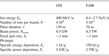
Already today, GSI accelerators deliver the most intense heavy ion beam for plasma physics experiments. The beam parameters of the new FAIR facility outnumber the current status in many respects: it is not only the absolute number of particles per bunch that will increase by about two orders of magnitude, but also the beam power will increase by a factor exceeding 400 due to pulse compression down to 70 ns (see Table 1). The specific energy deposition will increase from 1 kJ/g, which is a typical value for current experiments to about 150 kJ/g. This opens the possibility to reach out into currently inaccessible parameter regimes for HED states of matter, which is synonymously also called the regime of WDM (Varentsov et al., Reference Varentsov, Ternovoi, Kulish, Fernengel, Fertman, Hug, Menzel, Ni, Nikolaev, Shilkin, Turtikov, Udrea, Fortov, Golubev, Gryaznov, Hoffmann, Kim, Lomonosov, Mintsev, Sharkov, Shutov, Spiller, Tahir and Wahl2007).
Comparison of the current heavy ion beam parameters at GSI with those expected at FAIR

1.3. Experimental Methods
Due to their high kinetic energy, heavy ions penetrate deep into the volume of the target where they deposit the energy along the ion trajectories. This interaction mechanism constitutes an effective volume heating of the sample with low gradients, as long as ion range is large compared to the target dimension. In an accelerator experiment, the particle number N and the particle energy E 0 is well determined. Thus the total beam pulse energy is known with high precision. The spatial and time dependent energy deposition profile inside the target volume can be derived from the intensity distribution during the beam pulse and the radial intensity distribution of the beam focus. Ion beam induced high energy density states are therefore characterized by a precise knowledge of the initial conditions, which no other method can give in this way. It is very important to note that the statistical significance of the data will only be limited by the maximum target exchange frequency. This allows a large number of single shot experiments that is also difficult to achieve with other methods. The experiment aims for the highest possible specific energy deposition (E s) in matter.
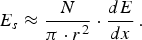
This equation shows that the specific energy deposition scales with the ratio of the total particle number N to the focal area r 2. These parameters can be varied in the experiment, whereas the stopping power of matter (dE/dx) is a material property, and may change drastically if the material turns into plasma. Ionization degree, temperature, and density are key parameters and they change dynamically during the experiment. An ion beam pulse, which is of short duration, penetrates into the target volume, and the heating process occurs during a time span that is short compared to the hydrodynamic response time. The fast heating process forces the target atoms to rearrange. As a result, it is predicted that target states will be reached that are similar in temperature and density to the situation in the interior of planets, or to the conditions of a fusion target during the heating process.
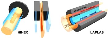
The hydrodynamic response of the irradiated sample, which is in a high energy density state, depends on the properties of the material. These properties are described by an EOS (Bushman & Fortov, Reference Bushman and Fortov1983; Di Bernardo et al., Reference Di Bernardo, Courtois, Cros, Matthieussent, Batani, Desai, Strati and Lucchini2003; Eliezer, Murakaml & Val, Reference Eliezer, Murakaml and Val2007; Fortov, Hoffmann & Sharkov, 2008; Hoffmann et al., Reference Hoffmann, Fortov, Lomonosov, Mintsev, Tahir, Varentsov and Wieser2002; Lomonosov, Reference Lomonosov2007). One important aspect to obtain information on the EOS is a time and space resolved measurement of the dynamic density distribution inside a high energy density sample. During an irradiation experiment this density may vary by an order of magnitude starting from solid state density. In HIHEX experiments, the target density will decrease, LAPLAS experiments aim for high compressed samples applying low-entropy compression of a material like frozen H2 or deuterium (D2) ice that is enclosed in a cylindrical shell of a high-Z material like gold or lead (Tahir et al., Reference Tahir, Hoffmann, Kozyreva, Tauschwitz, Shutov, Maruhn, Spiller, Neuner, Jacoby, Roth, Bock, Juranek and Redmer2000, Reference Tahir, Adonin, Deutsch, Fortov, Grandjouan, Geil, Grayaznov, Hoffmann, Kulish, Lomonosov, Mintsev, Ni, Nikolaev, Piriz, Shilkin, Spiller, Shutov, Temporal, Ternovoi, Udrea and Varentsov2005, 2006). A scheme of this cryogenic target design is shown in Figure 1. Such type of experiment is suitable for studying the problem of H2 metallization or for creating physical conditions that are expected to exist in the interiors of the giant planets.
(Color online) Beam-target configurations of different Plasma Physics experiments. HIHEX experiment: to measure EOS data by quasi-isochoric heating and isentropic expansion; LAPLAS: low-entropy cylindrical compression of matter. The right part of Figure 1 shows a schematic view of the LAPLAS target.

For the LAPLAS scheme realization, a key problem is the creation of a specialized cryogenic system (SCS) intended for the supply of the experiments with the cryogenic targets. Note that one of the main requirements to the SCS is that for the proposed LAPLAS experiments cryogenic targets must be supplied at a rate of ≥1 target per hour. That is why practically all of the elements must be constructed in such a way that the SCS operation with free-standing targets (FST approach) may be realized.
The FST approach has been developed and examined at the Lebedev Physical Institute to prepare spherical cryogenic targets for controlled fusion experiments (Aleksandrova et al., Reference Aleksandrova, Koresheva and Osipov1999, 2002). A basic advantage of such an approach is the minimization of time and space scales of all working operations that ensures the possibility of (1) rapid target transport between SCS modules, and (2) continuous operation of SCS with a given rate of target delivery. Besides, the FST approach holds much promise if one uses the DT-mixture as a fuel core.
Before the actual design of SCS, much development work has been made on target fabrication, target manipulation, and target survival (Aleksandrova et al., Reference Aleksandrova, Belolipeckiy, Blazevic, Hoffmann, Kapralov, Koresheva, Nikitenko, Sergeev, Tahir, Timasheva, Tolokonnikov, Udrea, Varentsov and Weyrich2008). The obtained results (theoretical and experimental) are discussed below.
2. TARGET FABRICATION STUDY
2.1. Cylindrical Shell Fabrication
A cylindrical shell of gold or lead must be formed. Since these metals have similar mechanical properties concerning such as plasticity and hardness (on the Mohs scale, gold has a hardness of 2.5, and lead has a hardness of 1.5), one can expect that the fabrication problems will be similar. In this work, the approach to the lead shell formation has been studied.
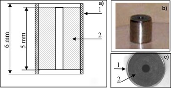
First, we examined different types of mechanical treatment of lead: turning, casting, mold pressing, and drilling. The most successful results were obtained during the mold pressing of a cylindrical sample from lead (diameter is 5 mm, and length is 5 mm) at room temperature. The matrix for the sample creation was a thin-walled stainless steel tube with the inner diameter of 5 mm and the wall thickness of 0.2 mm. In the next step, the lead cylinder faces were formed. The cylinder was pressed between two leucosapphire rods with polished faces, and the axial loading was generated. As a result, the sample had smooth polished faces. After that, an inner cylindrical cavity of 1 mm in diameter was drilled. Illustrations to the obtained cylindrical lead shell are shown in Figures 2a to 2c.
(Color online) Schematic of the lead shell location inside the stainless steel protection tube (a), and the photograph of the cylindrical lead shell (b) side view, (c) top view): 1, stainless steel tube with a thickness of 0.2 mm, 2, lead shell.

It should be noted that it is rather easy to obtain the polished faces of the lead cylinder. However, even a slight pressure of a nail can easily damage these faces. The problem of mechanical damage is also topical to the lateral surface of the cylinder. Therefore, the problem of surface condition survival during the free-standing target transport between the SCS modules will be considered in detail below (see Section 3.2).
2.2. Cryogenic Core Fabrication
A key issue for the SCS design is the technology choice for fabrication of a cylindrical cryogenic core.
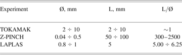
In the SCS design, the method of solid H2 or D2 extrusion through a special nozzle can be used. This technology is commonly used to prepare fuel targets for controlled fusion experiments. Cylindrical pellets of solid H2, D2, or tritium required for the continuous fueling of the TOKAMAK facilities (Kuteev et al., Reference Kuteev, Viniar, Sergeev, Tsendin and Kapralov1994; Sakamoto et al., Reference Sakamoto, Yamada, Takeiri, Narihara, Tokuzawa, Suzuki, Masuzaki, Sakakibara, Morita, Goto, Peterson, Matsuoka, Ohyabu, Komori and Motojima2006; Viniar et al., Reference Viniar, Skoblikov and Koblenz1997, Reference Viniar1999, Reference Viniar and Lukin2000, Reference Viniar, Geraud, Yamada, Sakamoto, Oda, Lukin, Umov, Skoblikov, Gros, Saksaganskiy, Reznichenko, Krasilnikov and Panchenko2004; Combs et al., 1993, Reference Combs and Foust1997, Reference Combs, Baylor, Fisher, Foust, Gouge, Pavarin, Sakamoto, Twynam, Watson and Yamada2001, Reference Combs, Baylor, Caughman, Foust, Jernigan, Maruyama, McGill, Rasmussen, Ridenaur and Watson2004). The targets' diameters and the length were in the range of 2-to-10 mm (see Table 2). To carry out the experiment in Z-pinch geometry, various authors (Friedman et al., Reference Friedman, Halpern and Brinker1974; Grilly et al., Reference Grilly, Hammel, Rodriguez, Scudder and Shlachter1985; Krause, Reference Krause1973; Pechacek et al., Reference Pechacek, Greig, Raleigh, DeSilva and Koopman1981; Sethian et al., Reference Sethian, Gerber and Sy1987) obtained long cylindrical threads of solid H2 and D2. The threads diameters were in the range of 0.04 mm to 1 mm and the length was 50-to-100 mm (see Table 2).
Comparative parameters of the solid-hydrogen cylinders used in different experiments on controlled fusion
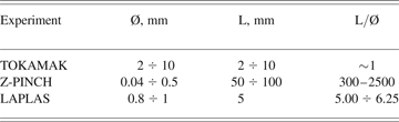
Notations: Ø is the sample diameter, L is the sample length
As it follows from Viniar et al. (2000), the solid H2 extrusion rate under temperatures of 10–11 K and extruder plunger load of ~10 MPa is about ~1 cm/s. Thus, the process of cylindrical solid-H2 core formation of 5-mm length takes less than 1 s. That means that the extrusion method allows working not only in the required regime of LAPLAS cylindrical target fabrication (one target per hour) but also in the regime with a high repetition rate (≥1 Hz), i.e., there it is a perspective for use in the inertial fusion energy reactors.
Another known technique to form solid H2 cylindrical pellets is the in-situ method. In the injection systems of TOKAMAKs with in-situ formation, H2 is filled directly into the locally cooled barrel of the injector, where the particle is formed. This kind of injector is commonly used in many laboratories at present. For example, the injector based on the in-situ method was designed in 1981 by Prut and Shibaev (Reference Prut and Shibaev1990), and was successfully used for the T-10 facility of the Russian Scientific Center–Kurchatov Institute of Atomic Energy (Moscow, Russia) from 1982 until 1992. The time required for the preparation of one pellet by this method is of about 15 min (in the optimum case). In the SCS design, the in-situ method can be used for gradual freezing of the solid-H2 (D2) core on the inner walls of the cylindrical lead shell.
Table 2 shows comparative parameters of the solid-H2 cylinders (used in different experiments on controlled fusion) made both by in-situ method and by extrusion. The transparence of the cylindrical solid H2 and D2 samples obtained in different experiments indicates a high homogeneity of the samples.
As follows from Table 2, the parameter combination of the target fuel core intended for our planned experiments was never realized before, neither by the in-situ method nor by extrusion. That means that during the SCS development, we need to optimize the experimental parameters. The quality of the obtained solid-H2 cylinders strongly depends on the correlation between the sample geometry, material purity, temperature regime of the processes of cryogenic core fabrication, and target delivery, and etc.
Particularly, the mechanical properties of solid H2 are extremely sensitive to the content of certain additives in the samples. For example, the presence of a neon additive of only ~0.01–0.001 atm.% in the n-H2 crystal considerably increases its plasticity (Alekseeva et al., Reference Alekseeva, Strjemechnyi and Chtcherbakov1995, Reference Alekseeva, Strjemechnyi and Butenko1997). The presence of even small isotopic additives (HD or D2) in H2 may cause sample embitterment and destruction (Alekseeva et al., Reference Alekseeva, Syrkin and Vashenko2003; Krupskiy et al., Reference Krupskiy, Leontieva, Indan and Evdokimova1976, Reference Krupskiy, Leontieva, Indan and Evdokimova1977). All kinds of additives, especially nitrogen, make D2 more brittle and extrusion appears to be impossible (Combs, Reference Combs1993). Besides, the additives freeze inside the extruder nozzle and block it up. From the above, we can make two conclusions: (1) the initial material (H2 or D2) must have a high material grade—not lower than 99.99%, (2) The SCS inner volume must be of high vacuum—not lower than 10−3–10−6 Torr.
Closing this section, we note, first of all, that both methods—in-situ and extrusion—can be considered as promising candidates for the solid-H2 core formation in the SCS. In addition, special features must be realized under the SCS operation, namely: H2 and D2 must be of a high material grade; the SCS inner volume must be of high vacuum.
2.3. Design of the Fabrication and Assembly Module
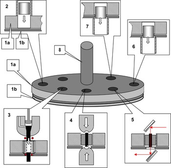
In this section, we give a description of a conceptual design of the fabrication and assembly module (FAM) for cryogenic targets' preparation based on the extrusion method. A principle scheme of FAM elements' mutual arrangement is shown in Figure 3.
(Color online) A principle scheme of FAM elements mutual arrangement. (1a and 1b) movable and stationary disks of the rotary assembly unit, correspondingly; (2) load unit of the lead shells; (3) module of the cylindrical solid hydrogen core formation and its assembly with the lead shell; (4) unit of cryogenic core faces formation; (5) quality control system of the cryogenic target core; (6) input unit of the finished cryogenic target to the delivery module; (7) rejected targets collector; (8) heat conductor.

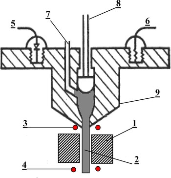
The FAM consists of two discs—movable (position 1a in Fig. 3) and stationary (position 1b) ones. Along the circle of the upper movable disc there are special holes (target sockets) where seven cylindrical targets can be placed. The upper disc revolves in the horizontal plane. The lower disc is fixed, and it also has functional holes designed for an ease of target operation. Rotation of the upper disc allows bringing the target socket from one unit to another in order to perform sequentially all the operations: lead shells loading, solid H2 core formation (position 3), target quality control (position 5), and etc. The fact that the upper disc's rotation axis is vertical allows one to fulfill a gravitation input of the lead shells into the FAM (position 2), the finished cryogenic target from the FAM into the delivery module (position 6), or the rejected target into the collector (position 7). Both discs are made of copper and sustained at 10–11 K. The disc cooling is realized through the cold conductor (position 8). The FAM is surrounded by a temperature shield that is sustained at low temperature due to the helium heat exchanger. Operating order of the FAM: (1) Cylindrical lead shell's loading under gravity (position 1, Fig. 3). (2) Through the disc rotation one of the shells is brought to the extrusion head (position 3, Fig. 3). The main elements of the extrusion head and the shell placing relative to the head are shown in more detail in Figure 4. (1) Then the D2 (or H2) cylinder extrusion is performed. To do that, the temperature of the extrusion head is raised up to T ≥10–11 K by a special heater (position 6, Fig. 3). At such temperature, solid D2 and H2 become flowable materials and their extrusion is possible. (2) Then the motor is turned on and, through the screw gear, sets in motion the plunger extruded D2 through the nozzle (position 8, Fig. 4). (3) From the nozzle the extruded solid H2 cylinder appears inside the hollow lead shell (position 1, Fig. 4). The operator runs the motor and controls the process of extrusion and filling the shell with D2 by means of a charge-coupled device-camera, which fixes the moment when the D2 (H2) cylinder appears from the lower part of the lead shell (is not shown in Fig. 4). (4) Then the upper (above the lead shell) and the lower (under the lead shell) parts of extruded D2-cylinder are cut-off. For this purpose, two pairs of thin tungsten wires should be used (positions 3 and 4, Fig. 4). (5) Due to the movable disc rotation, the targets move to the unit of cryogenic core faces' formation (position 4, Fig. 4), where a special device squeezes the ends of the D2 cylinder toward the target center. (6) Due to the disc rotation, the prepared target is moved to the characterization unit (position 5, Fig. 4). The core characterization will be done by an optical method (Born & Wolf, Reference Born and Wolf1999). (7) Due to the disc rotation, the target is moved to the input unit of the delivery module (position 6, Fig. 4) and loaded gravitationally to the delivery module. In case of poor quality, the target is moved to the input unit of the rejected targets collector (position 7, Fig. 4).
(Color online) Schematic of extrusion head: (1) lead shell, (2) solid D2 (or H2) cylinder, (3 and 4) two pairs of hot cutting wires, (5) temperature sensor, (6) resistive heater, (7) D2 (H2) inlet channel, (8) plunger, (9) copper extruding head.

3. STUDY ON TARGET MANIPULATION
3.1. Target Delivery
In the delivery module, the free-standing cylindrical cryogenic target must be transported (gravitationally or electromagnetically) along the guiding tubes to the chamber center.
As lead is a very soft material, the shell must be inside a special protective capsule during the delivery stage. Our experiments have shown (see Section 3.2) that a thin stainless steel tube (gravitational delivery) or a special driving capsule from the magneto-active material (electromagnetic delivery) can be successfully used for target surface protection. In this section, we consider both variants of cryogenic target delivery.
3.1.1. Electromagnetic Delivery
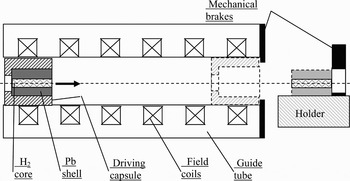
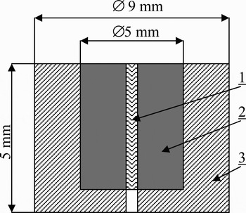
Figure 5 shows a schematic of the electro-magnetic delivery system for the cylindrical target enclosed inside a special driving capsule (Fig. 6).
A schematic of the electromagnetic delivery system (LAPLAS cryogenic target inside a ferromagnetic driving capsule).

LAPLAS cylindrical cryogenic target inside a driving capsule from magneto-active material: (1) cryogenic core, (2) lead shell, (3) driving capsule.

The driving capsule is accelerated in the electro-magnetic field of the delivery-system coils. At the guide tube outlet, the capsule is decelerated (mechanically or electromagnetically), and the target moves further inertially to get to the holder mounted in the center of the experimental chamber.
The operation of the electro-magnetic delivery system requires the application of a driving capsule fabricated from magneto-active material. A suitable material for the capsule is, for instance, a magnetically soft ferromagnetic (initial magnetic permittivity ≥250, density ~8 g/cm3). The weight of such a capsule is ~1 g for the geometry shown in Figure 6.
The delivery of the capsule with the target should occur at temperatures of 10–11 K—optimal temperature for cryogenic core fabrication. There is no information in the literature for ferro-magnetics retaining their properties at cryogenic temperatures. The possibility of accelerating a cylindrical ferromagnetic capsule in field coils at temperatures of 4.2–77 K was first studied (Koresheva et al., Reference Koresheva, Merkuliev, Nikitenko, Osipov and Tolokonnikov1988). The experiments showed that the initial magnetic permittivity of a cylindrical capsule fabricated from ARMCO (magnetically soft iron) at 10 K is µ~100, i.e., 2.5 times lower than the magnetic permittivity of this material at 300 K (µ = 250). However, this is quite enough to provide an efficient operation of the delivery system. Therefore, based on the studies conducted, we can recommend magnetically soft iron as a material suitable for target handling at 10–11 K.
To minimize energy consumption for target transport, the weight of the capsule should be made minimal at given dimensions. In this view, an optimal capsule material is a magneto-insulator consisting of the polymer matrix and magneto-active additives (Koresheva et al., Reference Koresheva, Aleksandrova, Osipov, Bazdenkov, Chtcherbakov, Koshelev, Nikitenko, Tolokonnikov, Yaguzinskiy, Baranov, Safronov, Timofeev, Kuteev and Kapralov2003, Reference Koresheva, Osipov, Tolokonnikov, Petrovskiy, Rezgol and Baranov2004). The use of a magneto-insulator instead of solid ferro-magnetics makes it possible to reduce the weight of the capsule about three to four times, with the magnetic activity of the capsule and its size preserved.
If a set of individual coils is provided to deliver the cylindrical target enclosed inside a driving capsule having a certain magnetic moment (see Fig. 5), the coils must be successively supplied by a suitable electric circuit with currents in synchronism with the movement of the capsule. Each field coil is operated by a rectangular current pulse that is always triggered when the front of the driving capsule is at a distance of the coil radius in front of the field coil for the next respective acceleration step.
The acceleration force F acting on the driving capsule is equal to the following expression (Koresheva et al., Reference Koresheva, Aleksandrova, Osipov, Bazdenkov, Chtcherbakov, Koshelev, Nikitenko, Tolokonnikov, Yaguzinskiy, Baranov, Safronov, Timofeev, Kuteev and Kapralov2003):

with,
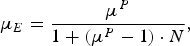
where P is the volume fraction of magneto-active additives in the polymer matrix, µ is the magnetic permittivity of the additives, the factor N depends on the driving capsule shape, µ0 is the absolute magnetic permittivity of the vacuum, I is the current amplitude, ω is the number of turns in the coil, the function Φ depends on the coil and capsule geometry and their relative position, l and l s are the length of coil and driving capsule, correspondingly, r is the coil inner radius, z is the coordinate of the driving capsule position inside the coil.
Eq. (2) is true for ferro-magnetic material with P = 1 and for magneto-insulators with 0.2 ≤ P ≤ 0.8, when the magnetic permittivity µm of the magneto-insulator can be given by the equation (Lichtenecker, Reference Lichtenecker1926): µm = µP.
Eq. (2) enables the optimization of the electro-magnetic delivery of a cylindrical target to the center of the experimental chamber.
To date, many elements of the electro-magnetic delivery system have been fine-adjusted as applied to the spherical cryogenic targets enclosed inside the cylindrical driving capsule made from ferromagnetic material (Koresheva et al., Reference Koresheva, Merkuliev, Nikitenko, Osipov and Tolokonnikov1988, Reference Koresheva, Aleksandrova, Osipov, Bazdenkov, Chtcherbakov, Koshelev, Nikitenko, Tolokonnikov, Yaguzinskiy, Baranov, Safronov, Timofeev, Kuteev and Kapralov2003, Reference Koresheva, Osipov, Tolokonnikov, Petrovskiy, Rezgol and Baranov2004, Reference Koresheva, Osipov and Aleksandrova2005).
3.1.2. Gravitational Delivery
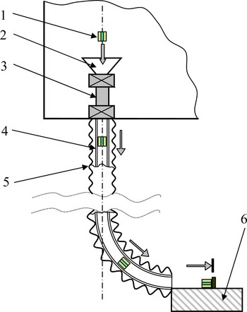
In this case, the target moves along the guides under gravity. Two types of motion—sliding and rolling—are possible. Figure 7 shows a variant of target sliding along the guide tube of the round cross-section. The tube (4) is fabricated from Teflon to reduce friction. On the outside, it is protected with a standard stainless-steel bellow tube (5).
(Color online) Scheme of target gravitational delivery using a guide tube. (1) target; (2) feeding funnel of the sluice; (3) vacuum sluice; (4) internal teflon tube; (5) protecting tube; (6) target holder.

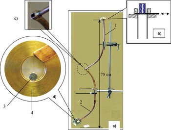
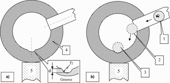
To clarify the specifics of gravitational delivery technique, we carried out a set of experiments using the designed and manufactured prototype model. A general prototype view is shown in Figure 8a. The prototype includes the following elements: unit for the cylindrical lead shell gravitational loading inside the copper tube of the round cross section, copper tube of round cross-section and inner diameter of 6 mm, copper tube of square cross-section 6 × 6 mm, holder with a special groove for target fixing (shown schematically in Fig. 9a). The scheme of inserting the cylindrical shell into the round cross-section tube is shown in Figure 8b. The round cross-section tube (1 in Fig. 8) was bent such that its upper end had the vertical axis of symmetry, and the lower end had the axis at an angle of ~45° to the horizon. The lower end of the round tube was jointed with the square-section tube as it shown in Figure 8c. A final delivery moment is fixing of a free-standing cryogenic target onto the groove of the holder (see Fig. 8d). In the side wall of the holder, there is a hole for feeding a shell from the square-section guide tube. A scheme of the target delivery to the holder is shown in Figure 9b.
(Color online) Prototype model of the delivery module: (a) general view, (b) unit for cylindrical shell gravitational loading into a guide tube with round cross section, (c) target axis turning unit (region of jointing the tubes of round and square cross-sections), (d) cylindrical lead shell in the holder made from brass; (1) copper tube of round cross-section and inner diameter of 6 mm; (2) copper tube of square cross-section 6 × 6 mm; (3) cylindrical lead shell, (4) target holder.

Cylindrical groove for fixing the target inside the holder. (a) A scheme of the holder with a groove of length h and radius r 2 (r 2 is equal to the external target radius, h is equal to the target length, and the groove depth is equal to d ≤ r 2); (b) A scheme of the target delivery to the holder; (1) cylindrical target rolling along the guiding tube of squared cross section, (2) moment of target injection inside the holder, (3) target is fixed in the groove, (4) holder, (5) cryocooler.

In all processes studied, the main force driving the cylindrical shell was the gravitational force. Tests were conducted under normal conditions (300 K, 1 atm.).
Several lead cylindrical shells were fabricated with the outer diameter of 5 mm, inner diameter of 1 mm, and length of 5 mm. The shells were placed inside a thin-walled stainless-steel tube (inner diameter, 5 mm; length, 6 mm; thickness, 0.2 mm) the way it is shown in Figure 2a. The stainless-steel tube plays a role of the element, which protects the outer surface of the shell from mechanical damage. The shell general view is shown in Figures 2b and 2c.
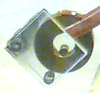
The following processes were studied: (1) Movement of the target along the guide tube: (a) sliding inside the round cross-section tube, (b) rolling inside the square cross-section tube. The experimental results have shown that both shell transportation techniques are suitable provided in case that the surface of the lead shell is protected from mechanical damage (see also Section 3.2). (2) Turn of the axis of the cylindrical shell by 90° (from the initial vertical position to the horizontal position).The experimental results have shown that target axis turning unit of our prototype (Fig. 8c) enables achieving a required turn of the axis of the cylindrical shell. (3) Target feeding into the holder of the positioning device. The experimental results have shown that the following operation must be done for a shell to be securely fed to and fixed in the cylindrical groove of the holder: (a) the shell must be braked at the outlet from the guide tube, (b) the contact area between the lead shell and the groove should be not less than 19% (this corresponds to the following groove parameters: groove radius is equal to the shell outer radius, groove deepness is ≥1 mm), and (c) a limiting shield should be used, which is removed before the target irradiation. The aim of the shield is (a) to protect the target from slipping off from the holder at the moment of feeding and (b) to protect the faces of the cryogenic core from evaporating throughout the target stay time in the chamber up to the moment of irradiation. Figure 10 shows a photograph of the holder assembled with the limiting shield made from acrylic plastic.
(Color online) Limiting shield from acrylic plastic mounted on the holder.

3.2. Target Surface Protection from the Mechanical Destruction during Delivery
The core material is solid H2. It is weak and fragile but it is protected from the direct mechanical damages by the outer lead shell. The most dangerous place of the cryogenic core is its faces. Therefore, it is necessary to apply special protective measures, for example, to place a target into the protective tube to avoid any mechanical damage of the core faces.
During target transport, it interacts with the inner surface of the delivery system elements, owing to there many cryogenic core displacements along the lead shell axis. To avoid the target quality degrading the inner diameter of the lead shell must be slightly increased on the ends due to a special face grooving, and it being known that the cryogenic core is formed so that it is tight against the shell groove.
The material of the outer cylindrical shell (lead) possesses such mechanical properties (it is soft and can be easily damaged, especially on the sharp ends of the cylinder) that results in the prompt degradation of the sample surface. The lead yield point is σT = 0.49–0.98 N/m2 [Wikipedia], which is one and a half or even two orders of magnitude less than for conventional construction materials (steel, aluminum alloys, brass, copper, and others). Therefore, the main problem during transport of the free-standing cylindrical target between the SCS modules is connected with the mechanical quality degrading of the lead shell surface.
Note that, generally, the problem of target surface mechanical-damage is mostly connected with the gravitational delivery application. In the system of the electro-magnetic delivery, we suppose to use a special driving capsule, which contains the target. Capsule application provides not only the target transport but also its protection from the mechanical damage and overheating.
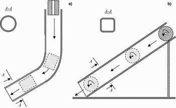
In order to study the peculiarities of the lead shell mechanical-damage during the process of gravitation delivery, there have been made several lead shells with the outer dimension of 5 mm, the inter dimension of 1 mm and 5-mm length. There were performed the following experiments: (1) Sliding friction realization. The sample slides down the copper tube of a circular section with the inter dimension of 6 mm and the length of 50 cm. The tube was curved in such a way that its upper end has a vertical symmetry axis, and the axis of the lower end makes an angle of 45° to the horizon (Fig. 11a). (2) Rolling friction realization. The sample rolls down the copper tube of a square section with a side of 6 mm and the length of 50 cm. This tube was at an angle of 45° to the horizon (Fig. 11b).
Schematic of the experiments on the lead shell pass under gravity through the different tubes. (a) shell sliding inside the tube of a circular section, (b) target rolling inside the tube of a square section.

The samples were examined under the microscope before and after the movement inside the tubes. The researches have shown that during the lead shell transport the lateral surface, its sharp ends, and faces are damaged on coming in contact with the surface of the guide tube: there appear rough edges, marks, grooves, and depressions on the shell.
Note that in the nonferrous metals (such as lead) during the temperature decreasing almost any mechanical characteristics are enhanced (Malkov et al., Reference Malkov, Danilov, Zeldovich and Fradkov1973, 219). Specifically, the limits of strength, elasticity, and hardness of the lead and also its plasticity and impact strength are increased. The working temperatures at which the target manipulation takes place are in the range of 10–11 K. Therefore, it may be expected that the problem of mechanical damage of the lead shell surface investigated at room temperature will be less acute at cryogenic temperatures. Experimentation at cryogenic temperatures is our near-term goal.
Besides, our investigations have shown that a simple and effective protective measure is a thin-walled tube of stainless steel that containes cylindrical lead shell. Figures 2a–c shows the layout of the lead shell inside the protective tube, and also a photograph of this assembly, which is made and tested in the scope of this work. In such geometry, the lateral surface of the lead shell, its faces and also the faces of the cryogenic core are protected from the mechanical destruction because the length of the protective tube is 1 mm longer than the target one. Note that the same stainless steel tube can be used also at the stage of the lead shell fabrication. In this case it is used as a forming element (matrix).
The experiments performed at room (300 K) and cryogenic (77 K) temperatures have shown that even under strong mechanical effects (vibrations, impacts); the assembly of the lead shell with a stainless steel tube reserves its configuration.
Note that coating the inner surface of the guide tubes and/or the target with Teflon can serve as an additional protective measure. Since Teflon has the least friction coefficient among the solid materials, then the application of such coating allows not only to protect the target surface from the mechanical damage but also to minimize the heat released due to moving target friction on the guide tube wall.
3.3. Holder of the Cryogenic Target Positioning System
Up to the time of irradiation, the axis of the target should be exactly adjusted relative to the axis of the irradiation beam. For this purpose, the target is positioned in the cylindrical groove of the cryogenic holder (Fig. 9b). This ensures the fixation of the target in the holder and a good heat exchange between the target and the holder. In turn, the holder is in thermal contact with the cryocooler's heel. Its cooling can be done, for instance, using DE204SL or SRDK-408D models (manufactured by Sumitomo Heavy Industries, Ltd., Tokyo, Japan), which are based on the modified two-stage Clifford-McMahon refrigeration cycle.
It is assumed that in the LAPLAS experiments, the energy deposited on-target by heavy-ion beam is several tens of kJ. Herewith, the target and the adjacent structural elements would be transformed into plasma and vapors. It is desirable, therefore, that the destructible part of the target holder is simple, inexpensive, and easily replaceable. This should be taken into account when designing the holder. Besides, the target holder should be designed such as to rule out the breakdown of the cryocooler components from the shock wave emerging at the shot.
A serious problem is that after the ion beam shot, the vapors of lead and other substances would be deposited on the walls of the experimental chamber, and elements inside it. If the experimental chamber is assumed to be a sphere of 3 m in diameter, it is easy to calculate that after each shot, a layer of lead of about 3 nm thick would be deposited on the surface of the chamber (at the weight of a target of about 1 g). A layer of 0.3 µm would be deposited after 100 shots. This “coating” would inevitably disturb the operation of unprotected optical, mechanical, and electronic units inside the chamber. The closer these elements to the target, the greater the impact would be.
In this respect, the target delivery system and elements of the target holder, and the cryocooler are the most critical components, as they are in the immediate vicinity of the target. Protection of these components is absolutely necessary. It can be realized, for instance, by mounting protecting shields, as well as moving the critical elements to a required distance away from the target before the shot, etc.
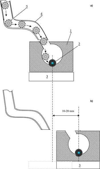
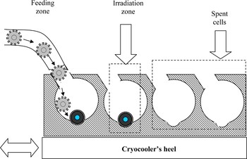
Figure 12 shows one of the possible layouts of handling the target in the experimental chamber. To protect elements of the delivery system from destruction, the holder, after the target is loaded into it (Fig. 12a), is moved away to a safe distance (Fig. 12b), and only after that the fine adjustment of the position of the target and its illumination are done. Figure 13 shows a schematic diagram of the holder for the case of continuous supply of targets to the irradiation zone.
(Color online) Possible scheme of handling the target in the experimental chamber: (a) holder in position to receive the target from the delivery system, (b) holder in position for target positioning and irradiation. (1) holder, (2) target; (3) heel of the cryocooler; (4) guide tube of the delivery system, (5) positions of the target in the process of delivery (the rolling variant).

(Color online) Schematic diagram of the holder for the case of continuous supply of targets to the irradiation zone.

The stage of target positioning is characterized by degrading effect of radiation heat transfer from the hot chamber wall (T = 300 K) to the cylindrical cryogenic target (T = 10–11 K) as well as of contact heat-exchange between the target and the holder. The optimal choice of the experimental conditions at which the target does not loose its quality is one of the most important tasks while creating the SCS. Thus, we must solve not only the problems of target fabrication and manipulation, but also the problems of target quality survival during target delivery and positioning. A thorough analysis of this problem will be given below.
4. TARGET SURVIVAL STUDY
Radiation heat transfer from the hot wall to the target can result in the cryogenic core heating above the triple point of the fuel matter, which in turn, results in fuel melting and flowing out from the inner cavity of the cylindrical target shell. We start the study of this process from the following moment. The cylindrical cryogenic target (optimal temperature 10–11 K) is placed in the groove (Fig. 9b) of the holder, and the holder temperature should be determined. The holder with the target is placed at the center of a vacuum chamber with hot walls, and the walls temperature is 300 K.
An initial estimation of the characteristic time of thermal processes can be obtained from a study based on using the Fourier number as a simulation criterion of the nonstationary thermal processes. The Fourier number (F) characterizes the correlation between the rate of thermal conditions change in the environment and the rate of temperature field transformation inside the analyzed system (it is a cryogenic target in our case). The Fourier number depends on the characteristic system dimension and the thermal diffusivity coefficient:

where l is the characteristic linear dimension of the system, τ is the characteristic time of external conditions change, a = λ/(Cρ) is the thermal diffusivity coefficient, λ is the thermal conductivity coefficient, ρ is the density, C is the specific thermal capacity.
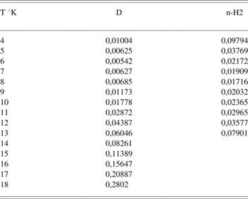
The parameter τ = l 2/a may be considered as a quite characteristic time for the thermal processes analyzed in our study Siegel & Howell (Reference Siegel and Howell1972). There were made calculations of the characteristic times τ for the cryogenic target with the following linear dimensions: 2.1 mm—wall thickness of the metal shell, and 0.4 mm—solid-H2 core radius. The thermal physic properties of the materials used in the calculations are taken from Beliaev & Riadno (Reference Beliaev and Riadno1993), and the results of calculations are shown in Tables 2 and 3.
Characteristic times of thermal processes for hydrogen isotopes, sec

It is obvious that thermal processes in gold are the most rapid ones. The thermal processes in the H2 isotopes are slower than in metals (Au, Pb). This means that the time estimations obtained for the metal shell are of «lower estimate», i.e., the process of fuel heating is not quicker than the process of shell heating.

Taking into account the above, let us estimate the rate of cylindrical shell heating. In general, the thermal conductivity equation without any internal sources is:
Volume—integrated Eq. (4) has the form

Then, using the Gauss-Ostrogradskij theorem (or divergence theorem), we obtain

According to the Fourier formula we have the relation for the heat flux Q

and, as a consequence, equation
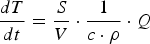
where S is the cylinder surface area, V is the cylinder volume, c and ρ are the thermal capacity and density of the shell material. If heat input to the target is caused by only thermal radiation from the hot chamber wall then Eq. (8) is of the form

where α is the absorption coefficient, β is the emissivity factor, σ is the Stefan-Boltzmann constant, T c is the chamber wall temperature. Since in our case, the target temperature is considerably lower than the chamber wall temperature, Eq. (9) can be written in the form:
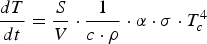
Let us suppose now that some part of the cylindrical shell with a relative square S t has the temperature T 0. This means that while the target is heated due to the thermal radiation, there is generated an additional heat flux, which for the cylindrical target has the following form (Beliaev & Riadno, Reference Beliaev and Riadno1993):

In this case, Eq. (10) takes the form:

where γ is the coefficient taking into account a degree of the heat contact imperfection (at ideal heat contact γ = 1), h is the cylinder length, r 1 is the internal cylinder radius, r 2 is the external cylinder radius.
Let us note that the coefficient γ characterizes the value of the contact thermal resistance and depends on many factors such as the surface finish class of contacting bodies, the presence of oxide or adsorbed film on them, the initial temperature difference of the contacting bodies, and other experimental conditions. Since the exact value of coefficient γ can be found only experimentally, in the calculations made below, the value γ is varied in a wide range of values (from 1 to 0.01).
There was created software to calculate the process of cylindrical target heating (Eqs. (10)–(12)). The calculation can be made for different geometrical parameters of the shells made of lead or gold. Thermal physic properties of these materials are given in Malkov et al. (Reference Malkov, Danilov, Zeldovich and Fradkov1973).
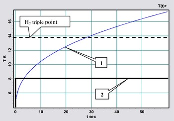
Using custom made software; calculations were made for heating the lead and gold cylindrical shells with the following parameters: external radius 2.5 mm, length 5 mm, internal radius 0.4 mm. The initial shell temperature T i = 4.2 K, which corresponds to the minimally possible target temperature. The results of the calculations have shown that in the case of radiation heating only (Eq. (7), T C = 300 K) the lead shell is heated from 4.2 K to 14 K (recall that at T = 13.96 K H2 begins to melt) for ≈ 30 s, and the gold shell—for ≈12 s. This is pressed for time to realize the process of target manipulation in the delivery and positioning stages.
Note also that the LAPLAS experiment require the target, which is placed onto a special holder of the positioning device. This means that besides the heat exchange caused by radiation (between the cold target and the hot chamber wall), there appears an additional (contact) heat exchange between the target and the holder. Let us also take into account the fact that from the moment of target arrival at the holder and until the moment of its irradiation by intense heavy ion beams, one need not only to perform an exact target positioning relative to the radiation axis, but also to control the quality of the cryogenic core and the target faces (final control). Of course, all the manipulations with targets must be within a certain margin of hours. If the holder is at room temperature, then the time interval is less than 1 s (Eq. (12)). This means that it is necessary to reduce the thermal target loads at the expense of developing the special protective measures. Application of a cryogenic holder is a way to meet the goal.
As mentioned above, a reliable target fixing, which provides stability of the target position and the maximal contact between the target and the holder, is a cylindrical groove with a length equal to the target one (h) and with a radius r equal to the external target radius (r = r 2). By changing the groove depth d (see Fig. 9a), we can change the contact area from St = 50% (d = r 2) and lower. The performed tests have shown that the target is stably fixed in the cylindrical groove with a minimal depth d = 1 mm (S t = 19%; see Section 3.2).
Figure 14 shows the calculation results of the lead shell heating caused by thermal radiation of the chamber wall (T c = 300 K) in the absence and in the presence of the shell contact with a cold substrate (cryogenic holder). As seen from the calculations, the lead shell (initial target temperature 4.2 K) reaches the holder temperature (8 K) for the time less than 50 ms, and whereupon, the shell temperature does not change.
(Color online) Calculation results of the lead shell heating due to the chamber wall radiation in the absence (1) and in the presence of the cryogenic holder (2). The calculation parameters: chamber wall temperature is T C =300 K, holder temperature is T 0 = 8 K, initial temperature of target is T i = 4.2 K.

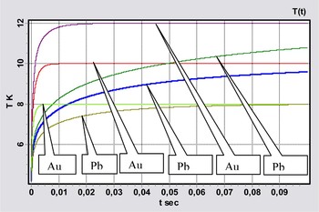
Figure 15 shows the lead and gold shell temperatures versus time at different holder temperatures. The shell is inside the vacuum chamber with a wall temperature of T c = 300 K. The holder temperature varies from 8 K to 12 K. The initial target temperature is equal to 4.2 K. All calculated curves have a similar form—for a relatively short-time the target temperature reaches the “saturation” temperature T H, which insignificantly exceeds the holder temperature T 0 and practically does not rise later. It is rather easy to estimate the value of this temperature using Eq. (12), in which we will set the time derivative equal to zero (i.e., the left side of equation):

(Color online) Heating of the cylindrical shell placed inside the chamber onto the cryogenic holder. The calculation parameters: Pb or Au cylindrical shell, diameter is 5 mm, length is 5 mm, thickness is 2.1 mm; T C = 300 K, α = 10%; T 0= 8 K, 9 K, 10 K, 11 K, 12 K; γ = 50%, S t = 10%, T i = 4.2 K

Table 4 shows typical times of the temperature balance settling between the lead shell (initial temperature (T i = 4.2 K) and holder for the conditions indicated in the caption for Figure 15. Here t H is the time of reaching T H. In the above calculation, the initial temperature of the lead shell T i was equal to the minimally possible target temperature T i = 4.2 K. This means that there must be added in scenario of the target fabrication and delivery one additional stage related to the shell cooling. Besides, the outer surface of the elements of the target delivery system (delivery from the fabrication module to the cryogenic holder) must be also cooled to the temperature of 4.2 K, and this will require a considerable consumption of the liquid helium—one of the most expensive components.
Shell temperature stabilization (TI = 4.2K) at different values of holder temperature (T0)

As an alternative, we consider the case when the value T i is close to the temperature at which the target was prepared in the fabrication module. Both for the extrusion and in situ methods, the optimal temperature is 10–11 K. Therefore, in the next series of calculations, we will take the initial temperature of the lead shell equal to T i = 11 K. Let us note also that the target is stably placed on the holder if the value of the relative contact area is in the range of S t = 20–50% (it has been found experimentally). Let us take the minimum value S t = 20%. According to the technical requirements, the target temperature T CT at the moment of its irradiation must not exceed the triple point temperature T tp for the corresponding fuel isotope. Its minimum value is ~4.2 K. Then, in the case of cryogenic H2 core, we have the following temperature range: T tp = 13.96 K > T CT ≥ 4.2 K, and in the case of D2 core: T tp = 18.65 K > T CT ≥ 4.2 K. Taking into account all stated above, we determine the cryogenic holder temperature as being equal to T 0 = 5, 8, 10, 13, 18 K. The coefficient ≥γ is equal to 50%
The obtained results testify that even at T i = 11 K the lead shell temperature reaches the saturation temperature T H (it is close to the holder temperature T 0) for a short moment of time tH, which does not exceed 1 s.
Thus, using a cryogenic holder, we can protect the target from the thermal radiation of the chamber wall and fix the target temperature in the ranges stated by the technical requirements.
There remains to find out the role of coefficient γ, which describes a degree of the heat contact imperfection. We have stated earlier that its exact value can be determined only experimentally. Therefore, in the current stage of researches, we can only vary γ in a wide range of values. Since at γ = 50% the value of t H (which is the time of reaching the saturation temperature) does not exceed 1 s, then in our calculations, we take only smaller values of γ: γ = 30, 10, 5%. The obtained results are shown in Table 5. It is obvious that even in the case of γ = 5%, a thermal equilibrium between the shell and the substrate (at minimum value of S t = 20%.) is reached rather quickly—for the time less than 20 s, and the saturation temperature is close enough to the holder temperature, i.e., T H ≈ T 0 = 18 K (see Table 5). In these calculations, the initial lead shell temperature is 11 K. Thus, our study has shown the following: (1) During target positioning at the center of the experimental chamber, the target must be on the cryogenic holder. The holder temperature T 0 is 4.2 K ≤ T0 < 13 K for H2 and 4.2 K ≤ T0 < 18 K for deuterium. This allows providing the required target temperature during its irradiation in a full compliance with the technical requirements. The initial target temperature T i must be close to the temperature at which the target was prepared in the fabrication module, i.e., T i = 10–11 K (optimum temperature for the extrusion and in-situ methods). (2) The efficiency of heat exchange between the holder and the target depends on (a) relative contact area S t and (b) coefficient γ. The calculations have shown that (1) the efficient heat exchange between the target surface and the holder is provided even at a very small value γ = 5% and small relative contact area S t = 20%, and (2) the exact value of coefficient γ must be found out experimentally, i.e., it is necessary to make further investigations in this area. Note that the higher the surface treatment and their cleanness, the higher the coefficient γ.
Shell temperature stabilization at different values of parameter γ

5. SCS CONCEPTUAL DESIGN
A peculiarity of the technical approach under the SCS designing is concerned with the requirement of target delivery at the chamber center in a repetition-rate mode. To meet this goal, the SCS design is based on the FST approach, which makes it possible to deliver the targets into the chamber center with the necessary rate (≥1 target per hour).
A general layout of the design options for the SCS is shown in Figure 16. The distinctive features of the design are: (1) Gravitational delivery of a target to the chamber center. (2) At all production stages (fabrication, assembly, delivery, positioning), the target is in a protective stainless-steel tube (see Fig. 2).
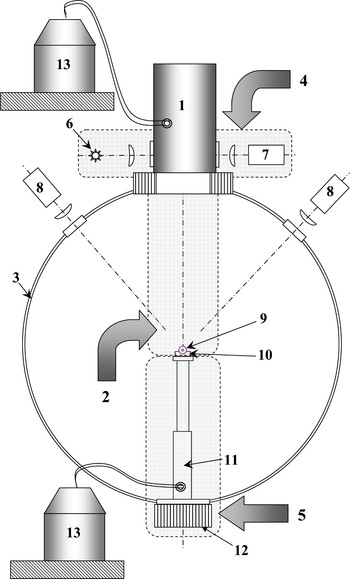
(Color online) SCS design option based on gravitational delivery of the cylindrical cryogenic targets. (1) FAM - module for cryogenic-core fabrication and its assembly with outer lead shell; (2) Cryogenic-target delivery and positioning module; (3) experimental vacuum chamber; (4) Cryogenic-target quality control system; (5) Cryogenic-target positioning system; (6) light source; (7,8) CCD cameras of quality control system; (9) cryogenic target; (10) cryogenic target holder; (11) cryocooler; 12 –hexapod, (13) refrigeration system.

First, all elements of the SCS are to be assembled into one device attached to the experimental vacuum chamber. A series (seven pieces) of cylindrical shells are loaded into the FAM (Fig. 3(1)), which is followed by evacuation of the internal volumes of the SCS and their cooling to the working temperature. After its fabrication in the FAM, a cryogenic target is to pass the preliminary optical control (Fig. 3(5)). The required optical elements (objective lenses, condensers, etc.), a source of probe radiation (Fig. 16(6)) and a charge-coupled device camera (Fig. 16(7)) make the cryogenic target quality control system (Fig. 16(4)).
If the test is successfully passed, the target is fed to the delivery module (Fig. 16(2)). The figure does not show this module in detail and only singles out the area where this system is located.
By means of the delivery module, the target (Fig. 16(9)) gets to the cryogenic holder (10) fixed on cryocooler heel (11), the temperature of which does not exceed 10–11 K. The holder orients the axis of the target in a given direction (in parallel with the axis of the beam). The temperature of the target is maintained to be not higher than 10–11 K by means of a cryocooler (12), and cooled radiation shields (not shown in Fig. 16).
Preliminary adjustment of the delivery module and the holder, as well as regulation of the linear position of the target by the XYZ axes and its final adjustment are done by means of the positioning subsystem, which is placed outside the vacuum chamber. It includes the hexapod-like adjustment unit (13) and two charge-coupled device cameras (8) equipped with required optics and also placed outside the vacuum chamber under an angle of ~90° in the plane perpendicular to the beam. The charge-coupled device cameras are intended to control the position of the target and also to perform its final characterization.
Let us recall that the SCS system must work in a repetition rate mode of cryogenic targets supply to the irradiation zone. Figure 13 presents a schematic diagram of the holder for that case.
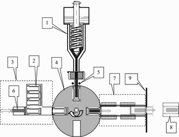
Figure 17 shows another possible SCS design (Koresheva et al., Reference Koresheva, Osipov and Aleksandrova2005). The distinctive features of this design are as follows: (1) cryogenic core formation using extrusion method, (2) electromagnetic delivery of a target to the chamber centre, (3) the target is inside a driving capsule from magneto-active material at all production steps. The system operates according to the following scenario: (1) Loading the driving capsules with cylindrical lead shells into the rotational disk. (2) Transport (by turning the rotational disk) of one capsule with the shell to the site of assembly with the cryogenic core. (3) Formation of the cryogenic core by means of extrusion, gravitational loading of the cryogenic core into the shell and cutting the upper end of the core using the wire loop. Preliminary characterization of the cryogenic target. (4) Transport of the capsule with the target to the inlet of the delivery system. (5) Electromagnetic delivery of the capsule with the target to the centre of the chamber. (6) Brakeage of the capsule at the outlet from the delivery system and inertial delivery of the target to the cryogenic holder placed in the chamber center. (7) Positioning and final characterization of the cryogenic target.
SCS design option for the repetition-rate fabrication and electromagnetic delivery of the free-standing cylindrical cryogenic targets to the center of experimental chamber. (1) Module for cryogenic core fabrication using extrusion method, (2) assembly element consisting of Pb shell and a driving capsule; (3) module for lead shell and driving capsule rep-rate loading into the rotational disk (4); (5) wire loop; (6) pusher; (7) module for finished cryogenic target electromagnetic delivery to the target positioning device disposed in the experimental chamber center; (8) target on the top of positioning device; (9) capsule bracker.

The final choice of the SCS design will be done after the geometry and overall dimensions of the experimental chamber for the LAPLAS experiments will be defined.
6. SUMMARY
For the first time, a thorough analysis is performed of the problem on repetition rate fueling of the LAPLAS experiments with free-standing cylindrical cryogenic targets.
Possible approaches to fabrication of the target elements—cylindrical cryogenic core and cylindrical lead shell—have been studied. Our analysis has shown that both the in-situ and the extrusion methods can be used for cryogenic core formation. A design of corresponding module for repetition-rate cryogenic core formation and assembly with cylindrical shells was proposed.
It has been shown experimentally that the mold pressing is a perspective method for fabrication of the cylindrical lead shell. Using this method, a set of the lead shells has been manufactured, which were then used in the test experiments.
Cylindrical cryogenic target transportation along the guide tubes of different cross-sections (round and squared) has been proposed as the basic technical approach for creation of the target delivery module (gravitational or electromagnetic). Realization of this approach was confirmed in a set of the test experiments carried out on the prototype created in Lebedev Physical Institute. The prototype consists of the following main elements: unit for target gravitational loading, round and square cross-section guiding tubes, holder with a special groove for target fixing. Experimentally it has been demonstrated the following: (1) target gravitation loading into the round cross-section tube, (2) target delivery along the guiding tubes at the distance of 0.75 and 1.5 m (supposed radius of the chamber), (3) target axis rotation on 90° at the area of coupling of round and square cross-section tubes, (4) target injection from the square cross-section guiding tube into the holder, (5) target fixing in the groove when the contact area between the target and the groove is not less than 19%.
These experiments have also shown that the lead shell surface and faces must be protected from the mechanical destruction during target delivery along the guiding tubes. It has been proven experimentally that a thin-walled stainless steel tube is a simple and effective protective measure.
Problem of cryogenic target survival inside a vacuum chamber with the hot wall has been studied theoretically. It is shown that target must be placed in the cryogenic holder (at optimal temperature 10–11 K) in order to guarantee cryogenic core survival during the positioning stage.
Two conceptual designs of the SCS are proposed basing on the FST principle. Both designs serve for cylindrical cryogenic targets repetition-rate fabrication, delivery and positioning in the center of experimental chamber.
As a result of our activity, a scientific-technology base is created, which will allow building up a SCS for repetition-rate supply of the LAPLAS experiments with free-standing cylindrical cryogenic targets.
ACKNOWLEDGEMENT
This work has been supported by GSI in the frame of a Research and Development Contract “Design and feasibility study on fabrication and manipulation of HEDgeHOB cryogenic targets.”