1. Introduction
Periodic maintenance and safety evaluation of tall structures is very much essential to minimize the impact of the disaster, which often results in loss of life and property. The safety evaluation of structures is carried out through periodic visual inspection, maintenance, and dynamic analysis. Visual inspection, painting/ cleaning are done manually, even in a very risky structural situation. Due to the complex structural plan, it is often found very difficult and expensive for human operators to access remote locations. The extraction of dynamic data for structural analysis is mainly done by installing a vast number of sensors on the civil structure, which requires huge instrumentation, and also, it is a very costly affair and time-consuming. Much research is found in the literature on wall-climbing robots for their applications in the cleaning, inspection, and maintenance of various structures. One of the essential uses of wall-climbing robots is autonomous inspection and monitoring of steel structures. The inspection speed and cost reduction can be significantly improved by employing instrumented wall-climbing robotic system. Research on wall-climbing robots will be beneficial, especially for automatic precise (surface and subsurface) inspection of complex steel structures.
Wall-climbing robots with unique locomotion techniques can provide effective autonomous mobility for structural health monitoring and inspection of civil infrastructures [Reference Zhu, Yi, Wang, Lee and Guo1, Reference Nguyen and La2, Reference Abdulkader, Veerajagadheswar, Lin, Kumaran, Vishaal and Mohan3]. Many research works are focused on developing wall-climbing robots using various locomotion and adhesion [Reference Chu, Jung, Han and Hong4, Reference Schmidt and Berns5] techniques. The adhesion mechanism for wall-climbing robots is essential for holding the robot and the locomotion mechanism for robot mobility along the vertical/inclined wall surface. Wall-climbing mechanisms developed based on the concept of vortex suction [Reference Koo, Trong, Moon, Koo, Park and Choi6] and universal vacuum gripper [Reference Fujita, Ikeda, Fujimoto, Shimizu, Ikemoto and Miyamoto7] do not require perfect sealing at the interface of the robot and wall surface as required in the case of active vacuum suction cup technique [Reference He, Xu, Zhou and Wang8]. However, wall-climbing robot locomotion to overcome irregularities due to large slots, large gaps/cracks, and large obstacles on the wall surfaces has not been studied so far. The interruption in power supply in the active pneumatic suction modules may also lead to the robot falling from the vertical surfaces.
Wall-climbing mechanisms developed based on bio-inspired adhesive [Reference Liu and Seo9] and electro-adhesive [Reference Sabermand, Ghorbanirezaei and Hojjat10] are very useful options irrespective of the building wall materials used. Research is still going on to overcome their limitations for wall climbing, such as payload capacity, net adhesion force for climbing, and smooth attachment and detachment issues in the long run. A wall-climbing robot, named ‘W-Climbot’ [Reference Guan, Zhu, Wu, Zhou, Jiang, Cai, Zhang and Zhang11], was built with a modular design approach that shows superior maneuverability and it is extremely good in grasping and manipulating objects. The biped design with multi degrees of freedom (DOF) motions of the wall-climbing robots may be well suited for narrow and cluttered steel structures like trusses, poles, or bridges, especially wall transitions and obstacle avoidance [Reference Guan, Zhu, Wu, Zhou, Jiang, Cai, Zhang and Zhang11, Reference Tummala, Mukherjee, Xi, Aslam, Dulimarta, Xiao, Minor and Dang12, Reference Mazumdar and Asada13]. Still, it may not be more efficient for large continuous steel structure inspection and maintenance scenarios compared to robots with continuous type locomotion. The wall-climbing mechanism was developed based on three multi-modules linked with rotational compliant joints [Reference Nam, Oh, Lee, Kim and Seo14, Reference Lee, Wu, Kim and Seo15]. The absence of steering ability may restrict its application in multi-steps, tight-corners, and other protruded wall surfaces. Compliant multi-body caterpillar track-type climbing robots [Reference Lee, Kim, Seo, Kim, Sitti and Seo16] are extremely good for wall transitioning ability. Unlike the multi-legged [Reference He, Xu, Zhou and Wang8] or biped climbing robot [Reference Tummala, Mukherjee, Xi, Aslam, Dulimarta, Xiao, Minor and Dang12, Reference Fan, Xu, Fang, Zhao and Zhu17, Reference Balaguer, Giménez, Pastor, Padron and Abderrahim18], these design configurations have advantages in achieving continuous motion during navigation [Reference Lee, Wu, Kim and Seo15, Reference Lee, Kim, Seo, Kim, Sitti and Seo16].
Hybrid omnidirectional magnetic wheels-based wall climbing strategies were adopted in [Reference Tavakoli, Lourenço, Viegas, Neto and de Almeida19]. The omni-climbing wheels and an arm in the robot design provide a better and easier way to maneuver from one wall to another. Although adding a four-bar arm configuration with omni-climbing wheels improves maneuverability, but it restricts its ability to convey obstacles on its path in the steel structures. A wall-climbing robot with permanent magnetic wheels that can move on the vertical surface of the steel bridge was developed in [Reference Wang and Kawamura20]. A wall-climbing robot [Reference La, Dinh, Pham, Ha and Pham21] comprises four motorized permanent magnetic wheels for creating the net adhesion force required to hold the robot on the vertical wall surface without consuming any power. The robot is capable of engagement and disengagement of the magnetic wheels using lifting mechanisms. This design configuration improves its maneuverability during one wall to another wall transitions. A wall-sticking drone [Reference Myeong and Myung22] is another way to reach the remote location of the structure rapidly. Still, payload capability of the robot and precise landing/perching and collision avoidance navigation systems with the vertical wall surface need further investigations.
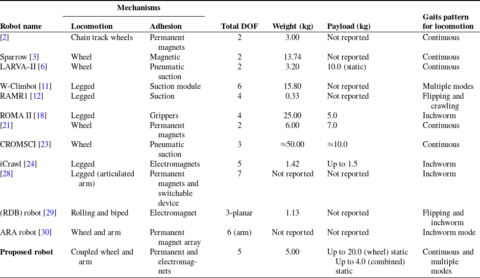
The literature [Reference Chu, Jung, Han and Hong4, Reference Schmidt and Berns5] revealed that the permanent magnetic adhesion-based mechanism is mostly implemented in the wall-climbing robot design for ferrous structures. It is a reliable mechanism compared to other conventional mechanisms such as pneumatic suction [Reference Hillenbrand, Schmidt and Berns23], electromagnets [Reference Khan, Chuthong, Do, Thor, Billeschou, Larsen and Manoonpong24], electrostatic [Reference Sabermand, Ghorbanirezaei and Hojjat10], and bio-inspired [Reference Liu and Seo9] based adhesion mechanisms. The robot design solely based on single locomotion such as wheel-driven [Reference Bisht, Pathak and Panigrahi25, Reference Bisht, Pathak and Panigrahi26], track-wheel [Reference Huang, Li, Xue, Chen, Liu, Leng and Wei27], multi-legged [Reference Pagano and Liu28], etc. may restrict its application for efficient coverage in complex wall situations. Although enormous work has been done in the area of wall-climbing robots, the combined locomotion concept is gaining momentum, with features such as wall-to-wall transitions, obstacle avoidance, and high-payload capacity in an efficient manner [Reference Phipps, Shores and Minor29, Reference Nguyen, Pham, Motley and La30, Reference Bisht, Pathak and Panigrahi31]. The prior art also suggests that the existing wall-climbing robots possess limitations for efficient maneuverability and better wall-adaptability while carrying additional payload. Mostly, the existing robots use single locomotion, lacking stability in a complex working environment. For complex wall scenarios, multi-modules and multi-legged wall-climbing robots are also being explored, but more DOF in the system design leads to inefficient and complex locomotion and adhesion force control. Therefore, there is a definite need to develop a simplified and reliable wall-climbing robot with sufficient payload carrying capacity along with simplified control strategies for industrial applications. The proposed robot performance has been further compared with the notable wall-climbing robots exhibiting the various locomotion gait patterns for structural inspection purposes. The performance comparisons with existing wall-climbing robots are presented in Table I.
Performance comparisons with the existing wall-climbing robots.

As evidence from Table I, the existing wall-climbing robot system design based on solely wheel locomotion achieves high-speed locomotion and steering, but has certain drawbacks viz., (i) unable to avoid obstacles in its path, (ii) unable to perform the wall transitions (in case of 3- dimensional structures), and (iii) lack of maneuverability for a curved and uneven surface. However, the arm locomotion-based existing wall-climbing robots overcome these drawbacks, but suffer from low-speed locomotion and complex control for simultaneous locomotion and adhesion. So, multi DOF of arm locomotion along with the wheel locomotion mode in robot design overcomes previously mentioned drawbacks. A comparative study of the proposed concept with the literature revealed that there are few solutions exist for a combination of wheel and arm locomotion used in wall-climbing robots [Reference Nguyen, Pham, Motley and La30, Reference Bisht, Pathak and Panigrahi31]. It is also found from the literature that the dynamic modelling of coupled wheel and arm locomotion and its motion planning in various wall-climbing situations have not been explored.
This article describes the development of a wall-climbing robot based on coupled wheel and arm locomotion concept which overcomes the individual drawbacks of single locomotion mechanisms. Integrating two identical mobile modules with a 3-DOF robot arm mechanism improves the overall mobility and maneuverability of the robot in comparison to existing robotic systems. Incorporating a switching mechanism in each mobile module brings easiness in the interchanging of coupled locomotion mode (wheel to arm or vice versa) by smooth attaching and detaching magnetic wheels. The robot uses its optimal DOF in motion according to the wall climbing situations. The wheel-locomotion can be preferred for plane wall surface climbing. The coupled wheel and arm-locomotion can be preferred for wall-to-wall transitions, obstacle avoidance, and uneven surface climbing in complex wall scenarios. The arm actuation of the proposed wall-climbing robot is inspired by inchworm motion. The developed mathematical models have been used for various trajectory simulations, and these are experimentally verified for the case of robot motion during vertical wall climbing and obstacle avoidance. The coupled wheel and arm locomotion simulations have been performed numerically by developing algorithms in MATLAB with a closed-loop PSO-PID feedback controller. Finally, the experimental locomotion trials of the developed robot have been successfully conducted, and both the simulations and experimental findings show a close correlation.
The rest of the paper is organized as follows. The wall-climbing robot design and working principle of the mechanisms are discussed in Section 2. Section 3 describes the mathematical modelling of coupled wheel and arm locomotion of the proposed robot for obtaining the kinematic, dynamic and state-space derivations. The controller design, motion planning and simulation strategies using developed algorithms in MATLAB are presented in Section 4. Section 5 discusses the robot prototype, electronic hardware and its control algorithms for motion trials of the robot. Results of simulations and experimental validation of the developed robot for the three cases of robot motions are presented in Section 6. In Section 7, conclusions are drawn from the work.
2. Robot design and mechanisms
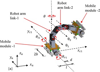
Figure 1 shows the schematic diagram of the proposed wall-climbing robot. It comprises three major components: mobile-module 1 (MM-1), robot arms (links 1 and 2) and mobile-module 2 (MM-2). The robot arm with three DOF is used to connect the two mobile modules. These mobile modules have two driving wheels and a group of inner and outer castor wheels.
Schematic diagram of the proposed wall-climbing robot.

The robot assembly consists of three mechanisms: wheel locomotion, arm, and switching. The wheel locomotion uses four-individual direct current (DC) motor drives. The arm locomotion uses three smart DC-servomotors, which are individually connected to the three revolute joints of the two-link robot arm. The proposed combined-locomotion mechanism works in two modes that is, wheel and arm. The first mode uses four magnetic wheel mechanisms for vertical surface climbing, and the second mode uses the coupled wheel and arm mechanism for wall-to-wall transition, obstacle avoidance, and uneven surface climbing. Both the wheel and arm motion may also be controlled/operated simultaneously during a transition from a plane surface with an obstacle or wall-to-wall transitions. The adhesion force of the robot for holding it on the vertical/inclined surface is achieved by the developed multi-layer magnetic wheel mechanism and an additional pair of electromagnets. The detailed design parameters, simulations, and experiments on various types of magnetic wheel mechanisms were presented in the authors’ previous work [Reference Bisht, Pathak and Panigrahi25, Reference Bisht, Pathak and Panigrahi26]. The wheel adhesion and friction force analysis, coefficient of friction (static and kinetic), have also been evaluated in a more detailed way.
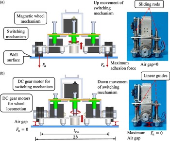
The switching mechanism has a significant role in changing the locomotion modes, that is, wheel to arm or vice versa, and also to reduce the overall turning load on arm joints by completely nullifying the magnetic wheel adhesion force by creating and controlling an air gap (
 $\delta _{a}$
). In Fig. 2, the up and down movement of the switching mechanism is performed with the help of a DC geared motor to actuate the lead screw pair relative to linear motion guides. However, three pairs of sliding rods along with linear guides linked with the base plate of the mobile module are used to constrain the axial (up and down) movement (
 $\delta _{d}$
) of the lead screw pair. There are four outer castor wheels spaced such that
 $l_{cw}\approx 2b$
along the length in the switching mechanism (Fig. 2(a) and (b)). Four inner castor wheels are also provided to give additional stability when the wall-climbing robot stands on only one mobile module, mainly when it uses the robot arm to move or position the other mobile module. Two electromagnets (optional) are used in the switching mechanism to take care of insufficient and variable adhesion force to avoid slipping, turning, or toppling the robot. Figures 2 (a) and (b) describe the principle of controlling the wheel adhesion force by creating an air gap using the switching mechanism. Before switching the locomotion modes (wheel to arm or vice versa), the axial movement of the lead screw pair should be greater than the magnetic wheel air gap (
 $\delta _{d}\gt \delta _{a}$
). Experimental studies [Reference Bisht, Pathak and Panigrahi25] indicate that the magnetic force completely disappears when the air gap (
 $\delta _{a}$
) becomes more than 10 mm, and accordingly, the parameter (
 $\delta _{d}$
) has been considered. A DC geared motor used in the switching mechanism with minimum stall torque of 3.5 nm has been considered from the design analysis to attach/detach the magnetic wheels.
Working principle of switching mechanism for magnetic wheel adhesion force control: (a) Wheels are in contact with the surface. (b) Wheels are detached from the surface.

3. Mathematical model
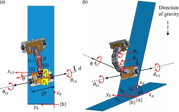
In this section, the mathematical model for coupled wheel and arm locomotion analysis of the wall-climbing robot is derived. The proposed design of the wall-climbing robot uses a combined (wheel and arm) locomotion mechanism depending on the type of complex wall terrain. The wheel locomotion mode of the wall-climbing robot is preferred for even/corrugated surface locomotion, and the arm locomotion mode of the wall-climbing robot is preferred for wall-to-wall transition, obstacle avoidance, and curved/uneven complex surface locomotion. A schematic for a generalized mathematical model of the coupled dynamics of the wall-climbing robot is shown in Fig. 3. The locomotion of two-mobile modules and robot arm can be interchangeable according to the wall-climbing situation.
Representation of DOF of wall-climbing robot, (a) planar view, (b) isometric view.

The wheel locomotion mode of the wall-climbing robot shows excellent maneuverability on a large plane of vertical, horizontal, and ceiling-type surfaces. Detailed maneuverability trials on a vertical wall of an autonomous wall-climbing robot for wheel locomotion mode can also be found in the authors’ previous work [Reference Bisht, Pathak and Panigrahi26]. However, here, combined multi DOF of arm locomotion and wheel locomotion mode is utilized in the proposed model. The robot arm mechanism is inspired by the inchworm actuation mechanism for wall-to-wall transition, obstacle avoidance, and uneven surface locomotion.
The motion of the robot using Mobile module-1 (MM-1) and the robot arm can be represented by two set of generalized coordinates such as
 $X_{m1}$
and
 $X_{a}$
, where
 $X_{m1}=[{x_{c1}}\ \ {y_{c1}}\ \ \theta\ \ {\theta _{r1}}\ \ {\theta _{l1}}]^{T}$
describes the generalized coordinates of the MM-1 and
 $X_{a}=\left[\theta _{1}\ \ \theta _{2}\ \ \theta _{3}\right]^{T}$
describes the generalized coordinates of the 3-DOF robot arm. Here,
 $x_{c1}\text{and} y_{c1}$
are the C.G. location of MM-1,
 $\theta, \theta _{r1}, \theta _{l1}$
denote the heading, right-wheel and left-wheel angular motion of MM-1, and
 $\theta _{1}, \theta _{2}, \theta _{3}$
denote the joint angles of the robot arm. For coupled wheel and arm configuration can be described in terms of a generalized coordinate vector
 $X=[{X_{m1}}\ \ {X_{a}}]^{T}$
,
 \begin{equation}X=\left[{x_{c1}}\ \ {y_{c1}}\ \ \theta\ \ {\theta _{r1}}\ \ {\theta _{l1}}\ \ {\theta _{1}}\ \ {\theta _{2}}\ \ {\theta _{3}}\right]^{T}.\end{equation}
According to the motion coordinates in configuration space (
 $X\in \mathbb{R}^{n}$
), the kinematic model can be obtained by comprising of motion and constraint equations of the robot. Kinematic modelling of the coupled wheel and arm locomotion of the wall-climbing robot is described in the next sub-section.
3.1. Kinematic model
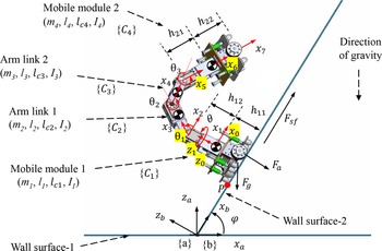
The schematic of a coupled wheel and arm locomotion mode of the robot is given in Fig. 4, where, {a} denotes an inertial frame attached to the ground surface, {b} is attached with the inclined/vertical wall, and {0} denotes the base frame of the mobile module-1. The frame {1} is placed at the center of gravity (CG) of the mobile module-1 (MM-1). Frame {2} defines the height of the MM-1. Frames {3}, {4}, and {5} are located at the first, second, and third joints of the robot arm, respectively, and frame {6} is located at the CG of the mobile module-2 (MM-2). Frame {7} defines the tip of the MM-2. The derivation of kinematic relations is obtained when the MM-1 is climbing using its magnetic wheels on the inclined wall surface while the MM-2 follow the desired trajectory using joint angles (
 $\theta _{1}, \theta _{2}, \theta _{3}$
) of the robot arm and motions of MM-1 (
 $x_{c1}, y_{c1}, z_{c1}$
,
 $\theta$
). The coordinate
 $z_{c1}$
is dependent on the
 $x_{c1}$
and
 $y_{c1}$
coordinates of the MM-1.
Frame assignment for the kinematic formulation of coupled wheel and arm locomotion.

Since either of the robot mobile modules which is in contact with the wall surface is subjected to the non-holonomic motion constraints which are expressed in the matrix form for coordinates
 $X$
as:
 \begin{equation}B(X)\dot{X}=0,\end{equation}
where,
 \begin{equation*}B(X)=\left[\begin{array}{c@{\quad}c@{\quad}c@{\quad}c@{\quad}c@{\quad}c} -\text{s} \theta & \text{c} \theta & -d & 0 & 0 & \vdots \\[4pt] -\text{c} \theta & -\text{s} \theta & -b & r & 0 & \mathbb{O}_{3\times 3}\\[1pt] -\text{c} \theta & -\text{s} \theta & b & 0 & r & \vdots \end{array}\right]\end{equation*}
Where,
 $\text{s}\ \theta =\sin \theta$
and
 $\text{c}\ \theta =\cos \theta$
. Also, from Fig. 3(a),
 $d$
is the distance from
 $P_{0}$
to
 $P_{c}$
,
 $b$
is the distance between the MM-1 axis of symmetry and the left and right drive wheels,
 $r$
is the radius of each magnetic wheel. Although the wall-climbing robot platform is non-holonomic, there is one motion constraint that is named as holonomic, and it is obtained by subtracting two pure-rolling constraints relations from Eq. (2), viz.,
 \begin{equation}2b\dot{\theta }=r\left(\dot{\theta }_{r1}-\dot{\theta }_{l1}\right)\!.\end{equation}
From Eq. (3), the obtained velocity constraint integrated into position constraint led to a relation,
 \begin{equation}\theta =\unicode{x03C8} \left(\theta _{r1}-\theta _{l1}\right)\!.\end{equation}
Eq. (4) clearly defines as a holonomic constraint equation, where
 $\unicode{x03C8}$
is defined as
 $\left(\tfrac{r}{2b}\right)$
.
Further, to define a matrix
 $S(X)$
which is a null space of the constraint matrix
 $B(X)$
, related such that
 $B(X)S(X)=0$
. The kinematic model of the proposed combined wheel and arm locomotion mode of the wall-climbing robot is given by:
 \begin{equation}\dot{X}=S(X)\zeta.\end{equation}
Where newly introduced variables,
 $\zeta (t)=\left[\begin{array}{c@{\quad}c@{\quad}c@{\quad}c@{\quad}c} \dot{\theta }_{r1} & \dot{\theta }_{l1} & \dot{\theta }_{1} & \dot{\theta }_{2} & \dot{\theta }_{3} \end{array}\right]^{T}$
and
 \begin{equation}SS(X)=\left[\begin{array}{c@{\quad}c@{\quad}c} \unicode{x03C8} (b\text{c} \theta -d\text{s} \theta ) & \unicode{x03C8} (b\text{c} \theta +d\text{s} \theta ) & \vdots \\[4pt] \unicode{x03C8} (d\text{c} \theta +b\text{s} \theta ) & \unicode{x03C8} (b\text{s} \theta -d\text{c} \theta ) & \mathbb{O}_{3\times 3}\\[4pt] \unicode{x03C8} & -\unicode{x03C8} & \\ \ldots & \quad\mathbb{I}_{5\times 5}\quad\ldots & \vdots \end{array}\right].\end{equation}
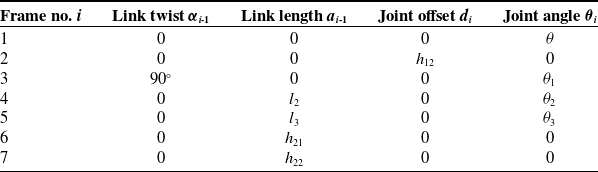
Table II shows the link-joint parameters for robot arm locomotion using Denavit–Hartenberg (D-H) convention. The D-H parameters in Table II are evaluated from robot schematic in Fig. 4.
D-H parameters of the wall-climbing robot working under arm locomotion mode.

The overall transformation matrix with respect to {a} in Eq. (7) is obtained by multiplying the individual transformation matrices for the forward kinematic model. This transformation matrix is given as,
 \begin{equation}{_{7}^{a}}{T}{}={_{ b}^{a}}{T}{}{_{0}^{b}}{T}{}\left({_{1}^{0}}{T}{}{_{2}^{1}}{T}{}{_{3}^{2}}{T}{}{_{4}^{3}}{T}{}{_{5}^{4}}{T}{}{_{6}^{5}}{T}{}{_{7}^{6}}{T}{}\right)={_{b}^{a}}{T}{}{_{0}^{b}}{T}{}{_{7}^{0}}{T}{}.\end{equation}
Overall transformation with respect to {0} is given by,
 \begin{equation}{_{7}^{0}}{T}{}=\left[\begin{array}{c@{\quad}c@{\quad}c@{\quad}c} \text{c} \theta \text{c}_{123} & -\text{c} \theta \text{s}_{123} & \text{s} \theta & {_{7}^{0}}{x}{}\\[4pt] \text{s} \theta \text{c}_{123} & -\text{s} \theta \text{s}_{123} & -\text{c} \theta & {_{7}^{0}}{y}{}\\[4pt] \text{s}_{123} & \text{c}_{123} & 0 & {_{7}^{0}}{z}{}\\[4pt] 0 & 0 & 0 & 1 \end{array}\right],\end{equation}
where,
 $ {_{7}^{0}}{x}{}=l_{2}\text{c} \theta \text{c}_{1}+l_{3}\text{c} \theta \text{c}_{12}+(h_{21}+h_{22})\text{c} \theta \text{c}_{123} $
,
 $ {_{7}^{0}}{y}{}=l_{2}\text{s} \theta \text{c}_{1}+l_{3}\text{s} \theta \text{c}_{12}+(h_{21}+h_{22})\text{s} \theta \text{c}_{123} $
,
 $ {_{7}^{0}}{z}{}=h_{12}+l_{2}\text{s}_{1}+l_{3}\text{s}_{12}+(h_{21}+h_{22})\text{s}_{123} $
.
Overall transformation with respect to {a} is expressed as,
 \begin{equation}{_{7}^{a}}{T}{}={_{b}^{a}}{T}{}{_{0}^{b}}{T}{}{_{7}^{0}}{T}{},\end{equation}
 \begin{equation}{_{7}^{a}}{T}{}=\left[\begin{array}{c@{\quad}c@{\quad}c@{\quad}c} \left(\text{c} \varphi \text{c} \theta \text{c}_{123}-\text{s} \varphi \text{s}_{123}\right) & \left({-}\text{c} \varphi \text{c} \theta \text{s}_{123}-\text{s} \varphi \text{c}_{123}\right) & \text{c} \varphi \text{s} \theta & x_{7}\\[4pt] \text{s} \theta \text{c}_{123} & -\text{s} \theta \text{s}_{123} & -\text{c} \theta & y_{7}\\[4pt] \left(\text{c} \varphi \text{s}_{123}+\text{s} \varphi \text{c} \theta \text{c}_{123}\right) & \left(\text{c} \varphi \text{c}_{123}-\text{s} \varphi \text{c} \theta \text{s}_{123}\right) & \text{s} \varphi \text{s} \theta & z_{7}\\[4pt] 0 & 0 & 0 & 1 \end{array}\right].\end{equation}
Where,
 $x_{7}=\text{c} \varphi \!\left(x_{c1}+l_{2}\text{c} \theta \text{c}_{1}+l_{3}\text{c} \theta \text{c}_{12}+\!\left(h_{21}+h_{22}\right)\!\text{c} \theta \text{c}_{123}\right)-\text{s} \varphi \!\left(h_{11}+h_{12}+l_{2}\text{s}_{1}+l_{3}\text{s}_{12}+\!\left(h_{21}+h_{22}\right)\!\text{s}_{123}\right)$
,
 $y_{7}=y_{c1}+l_{2}\text{s} \theta \text{c}_{1}+l_{3}\text{s} \theta \text{c}_{12}+(h_{21}+h_{22})\text{s} \theta \text{c}_{123}$
,
 $z_{7}=\text{c} \varphi \!\left(h_{11}+h_{12}+l_{2}\text{s}_{1}+l_{3}\text{s}_{12}+\!\left(h_{21}+h_{22}\right)\!\text{s}_{123}\right)+\text{s} \varphi \!\left(x_{c1}+l_{2}\text{c} \theta \text{c}_{1}+l_{3}\text{c} \theta \text{c}_{12}+\!\left(h_{21}+h_{22}\right)\!\text{c} \theta \text{c}_{123}\right)\!.$
The derived forward kinematic relations in Eq. (10) show the tip position (
 $x_{7},y_{7}, z_{7}$
) and orientation of mobile module-2 when the mobile module-1 and robot arm are in motion. The forward kinematic expression according to the D-H convention in Table II for the position and velocity of the robot components (MM-1, arm link-1, arm link-2 and MM-2) is also used for the derivation of net kinetic and potential energies. These energy terms are further used in the robot dynamic modelling and are described in the next sub-section. The abbreviations used in the above mathematical derivations are shown in Appendix A.
3.2. Dynamic model
In this section, the Lagrangian formulation is employed to derive the dynamic equations of the wall-climbing robot for combined wheel and arm locomotion. The Lagrange formulation for the kinematic constraint system is expressed as:
 \begin{equation} \frac{d}{dt}\left(\frac{\partial L\!\left(X,\dot{X}\right)}{\partial \dot{X}_{i}}\right)-\frac{\partial L\!\left(X,\dot{X}\right)}{\partial X_{i}}=F_{{G_{i}}}-{\sum }_{j=1}^{m}\lambda _{j}{b}_{i}^{j},\quad \text{where}\quad i=1\ldots ..n.\end{equation}
In the above equation,
 $j=m$
is the number of constraints,
 $i=n$
is the number of generalized coordinates, and
 ${b}_{i}^{j}$
are elements of the kinematic constraint matrix. Further, the dynamic system can be written in the following simplified form,
 \begin{equation}\frac{d}{dt}\left(\frac{\partial L\!\left(X,\dot{X}\right)}{\partial \dot{X}_{i}}\right)-\frac{\partial L\!\left(X,\dot{X}\right)}{\partial X_{i}}=F_{{G_{i}}}-\lambda B^{T}(X),\end{equation}
where,
 $L\!\left(X,\dot{X}\right)=K\!\left(X,\dot{X}\right)-U(X)$
,
 $K\!\left(X,\dot{X}\right)$
,
 $U(X)$
,
 $F_{{G_{i}}}$
, and
 $\lambda$
denote net kinetic energy, net potential energy, the generalized forces, and a vector of Lagrange multipliers, respectively.
The kinetic energy of the whole robot under wheel and arm locomotion is derived using velocity expressions of the robot components,
 \begin{equation}K\!\left(X,\dot{X}\right)={\sum }_{i=1}^{4}\frac{1}{2}\left(m_{i}{{_{ }^{i}}{V}{}}_{C_{i}}^{T}{_{ }^{i}}{V}{}_{{C_{i}}}+{{_{ }^{i}}{\omega }{}}_{i}^{T}{_{ }^{Ci}}{I_{i}}{}{_{ }^{i}}{\omega }{}_{i}\right),\end{equation}
where,
 $(i=1\text{ to }4)$
is the total number of links of the robot.
The potential energy is due to the non-planar robot motion under gravitational acceleration. The potential energy of the whole robot under combined locomotion is derived using position expressions of the robot components,
 \begin{equation}U(X)={\sum }_{i=1}^{4}\left(m_{i}g^{T}X_{ci}\right).\end{equation}
Details of these energy terms used in the dynamic formulation are given in Appendix-A. The governing dynamic equations for trajectory response simulations are obtained by using the Lagrangian method as given in Eq. (12) by substituting net kinetic energy and potential energy,
 \begin{equation}M(X)\ddot{X}+C\!\left(X,\dot{X}\right)\dot{X}+G(X)+F_{sf}A(X)=E(X)\tau -\lambda B^{T}(X).\end{equation}
Where,
 $X\in \mathbb{R}^{n}$
are the generalized coordinates for robot wheel and arm locomotion,
 $M(X)\in \mathbb{R}^{n\times n}$
is symmetric and positive definite inertia matrix,
 $C\!\left(X,\dot{X}\right)\in \mathbb{R}^{n\times n}$
is the Coriolis and centripetal force matrix,
 $G(X)\in \mathbb{R}^{n}$
is the gravitational force vector,
 $B(X)\in \mathbb{R}^{n\times m}$
is constraint matrix,
 $E(X)\in \mathbb{R}^{n\times (n-m)}$
and
 $A(X)\in \mathbb{R}^{n}$
are the input transformation matrices,
 $\tau \in \mathbb{R}^{n-m}$
is the input torque vector. Detailed expressions of these matrices and other used abbreviations are expressed in Appendix B.
From the quasi-static relations using the robot schematic in Fig. 4, the required minimum adhesion force
 $(F_{a})$
is expressed in Eq (16) to avoid the wheel locomotion failures such as sliding and toppling from the inclined/vertical wall surface,
 \begin{equation}F_{a}=\begin{cases} \max \left\{F_{as1},F_{at1}\right\}, & 0^{\circ}\lt \varphi \lt 180^{\circ}\\[4pt] \max \left\{F_{as2},F_{at2}\right\}, & 180^{\circ}\lt \varphi \lt 360^{\circ} \end{cases},\end{equation}
where,
 $F_{as1}$
and
 $F_{as2}$
are the net adhesion force in each mobile module to avoid slip mode of locomotion failure,
 $F_{at1}$
and
 $F_{at2}$
are the adhesion force in each mobile module to avoid toppling failure about the point
 $P$
in Fig. 4. The optimized adhesion force analysis from Eq. (16) suggests the minimum adhesion force is
 $\approx$
300 N in each mobile module is required for the stable locomotion of the proposed wall-climbing robot. In Eq. (15), the traction force
 $\left(F_{sf}=f\left(F_{a}, F_{g}, \varphi, \mu, sign\left(\dot{\theta }_{r1}, \dot{\theta }_{l1}\right)\right)\right)$
required for robot locomotion is a function of adhesion force, robot weight, wall inclination, surface friction, and direction of robot locomotion. An average value of the coefficient of friction
 $\mu =0.4$
has been considered in the trajectory tracking and path planning simulation [Reference Bisht, Pathak and Panigrahi25].
There are different cases of the robot motions for performing the desired climbing actions such as: vertical climbing and obstacle avoidance strategies. In Case-1, the robot arm motions are restricted/locked and both the mobile modules (MM-1 & 2) use wheel locomotion mode for the robot movement. In Case-2, MM-2 is detached from the wall surface and uses coupled motions of the MM-1 and robot arm for the robot movement. However, in Case-3, the robot MM-1 is detached from the wall surface and uses the coupled motions of the MM-2 and robot arm. These robot motions can be effectively used depending upon the wall climbing scenarios.
3.2.1. Case-1
The Lagrange formulation in Eq. (12) can be used to describe the robot locomotion for Case-1. The dynamic equations are expressed in Eq. (17) when both the first and second mobile modules are moving under wheel locomotion while arm joints are locked. When arm joints are locked, the MM-1 & 2 will have a common CG (
 $x_{12}\ y_{12}\ z_{12}$
) and heading angle (
 $\theta$
) and the joint parameters (
 $\theta _{1}\ \theta _{2}\ \theta _{3}$
) even now can be set as a rigid singular configuration of the arm. The dynamic equation of the system can be expressed as,
 \begin{equation}\left[\begin{array}{c@{\quad}c} M_{11} & M_{22}\\[4pt] M_{13} & M_{24} \end{array}\right]\left(\ddot{X}_{m12}\right)+\left[\begin{array}{c@{\quad}c} C_{11} & C_{22}\\[4pt] C_{13} & C_{24} \end{array}\right]\left(\dot{X}_{m12}\right)+\left(\begin{array}{c} G_{11}\\[4pt] G_{22} \end{array}\right)+F_{sf}\!\left(A_{m12}(X_{m12}\right)=\left(E_{m12}\tau _{m12}\right)-\left({\lambda B}_{m12}^{T}\left(X_{m12}\right)\right).\end{equation}
Where,
 $X_{m12}=[{x_{12}}\ {y_{12}}\ \theta\ {\theta _{r2}}\ {\theta _{l2}}\ {\theta _{r1}}\ {\theta _{l1}}]^{T}$
describes the generalized coordinates to represent the combined motion of MM 1 & 2, wheel driving torque of MM-1 & 2 is
 $\tau =\left[\tau _{r1}\ \tau _{l1}\ \tau _{r2}\ \tau _{l2}\right]^{T}$
,
 $B_{m12}\subseteq B_{m1}\cup B_{m2}$
,
 $E_{m12}\subseteq E_{m1}\cup E_{m2}$
, and
 $A_{m12}\subseteq A_{m1}\cup A_{m2}$
.
3.2.2. Case-2
The dynamic model in Eq. (15) is used to describe the robot locomotion for Case-2. The dynamic equations are further expressed in Eq. (18) to see the coupled behavior of wheel and arm locomotion,
 \begin{align} & \left[\begin{array}{c@{\quad}c} M_{11} & M_{12}\\[4pt] M_{13} & M_{14} \end{array}\right]\left(\begin{array}{c} \ddot{X}_{m1}\\[4pt] \ddot{X}_{a} \end{array}\right)+\left[\begin{array}{c@{\quad}c} C_{11} & C_{12}\\[4pt] C_{13} & C_{14} \end{array}\right]\left(\begin{array}{c} \dot{X}_{m1}\\[4pt] \dot{X}_{a} \end{array}\right)+\left(\begin{array}{c} G_{11}\\[4pt] G_{12} \end{array}\right)+F_{sf}\!\left(\begin{array}{c} A_{m1}(X_{m1})\\[4pt] \mathbb{O} \end{array}\right)\nonumber\\[5pt]& =\left(\begin{array}{c} E_{m1}\tau _{m1}\\[4pt] \tau _{a1} \end{array}\right)-\left(\begin{array}{c} {\lambda B}_{m1}^{T}\left(X_{m1}\right)\\[4pt] \mathbb{O} \end{array}\right),\end{align}
where,
 $X_{m1}=[{x_{c1}}\ \ {y_{c1}}\ \ \theta\ \ {\theta _{r1}}\ \ {\theta _{l1}}]^{T}$
describes the generalized coordinates of the first mobile module and
 $X_{a1}=\left[\theta _{1}\ \theta _{2}\ \theta _{3}\right]^{T}$
describes the generalized coordinates of the 3-DOF robot arm, wheel driving torque of MM-1 is
 $\tau _{m1}=\left[\tau _{r1}\ \tau _{l1}\right] ^{T}$
, robot arm driving torque is
 $\tau _{a1}=\left[\tau _{1}\ \tau _{2}\ \tau _{3}\right]^{T}$
,
 $B_{m1}\subseteq B$
,
 $E_{m1}\subseteq E$
and
 $A_{m1}\subseteq A$
.
The terms (
 $M_{12}$
and
 $C_{12}$
) in Eq. (18) denotes the dynamic interaction of the first mobile module with the robot arm of the wall-climbing robot. The terms (
 $M_{13}$
and
 $C_{13}$
) in Eq. (18) denotes the dynamic interaction of the robot arm with the first mobile module of the wall-climbing robot.
3.2.3. Case-3
The Lagrange formulation in Eq. (12) can be used to describe the robot locomotion for Case-3. It can also be easily obtained by rearranging the equations of motions in Eq. (18). The coupled dynamic equations for Case-3 are further expressed in Eq. (19),
 \begin{align}& \left[\begin{array}{c@{\quad}c} M_{21} & M_{22}\\[4pt] M_{23} & M_{24} \end{array}\right]\left(\begin{array}{c} \ddot{X}_{a}\\[4pt] \ddot{X}_{m2} \end{array}\right)+\left[\begin{array}{c@{\quad}c} C_{21} & C_{22}\\[4pt] C_{23} & C_{24} \end{array}\right]\left(\begin{array}{c} \dot{X}_{a}\\[4pt] \dot{X}_{m2} \end{array}\right)+\left(\begin{array}{c} G_{21}\\[4pt] G_{22} \end{array}\right)+F_{sf}\left(\begin{array}{c} \mathbb{O}\\[4pt] A_{m2}(X_{m2}) \end{array}\right)\nonumber\\[6pt]& \quad =\left(\begin{array}{c} \tau _{a}\\[4pt] E_{m2}\tau _{m2} \end{array}\right)-\left(\begin{array}{c} \mathbb{O}\\[4pt] {\lambda B}_{m2}^{T}\left(X_{m2}\right) \end{array}\right),\end{align}
where,
 $X_{m2}=[{x_{c2}}\ {y_{c2}}\ \theta\ {\theta _{r2}}\ {\theta _{l2}}]^{T}$
describes the generalized coordinates of the second mobile module and
 $X_{a2}=\left[\theta _{3}\ \theta _{2}\ \theta _{1}\right]^{T}$
describes the generalized coordinates of the 3-DOF robot arm, wheel driving torque of MM-2 is
 $\tau _{m2}=\left[\tau _{r2}\ \tau _{l2}\right] ^{T}$
, robot arm driving torque is
 $\tau _{a2}=\left[\tau _{3}\ \tau _{2}\ \tau _{1}\right]^{T}$
,
 $B_{m2}\subseteq B$
,
 $E_{m2}\subseteq E$
and
 $A_{m1}\subseteq A$
.
The terms (
 $M_{21}$
and
 $C_{21}$
) in Eq. (19) denotes the dynamic interaction of the second mobile module with the robot arm of the wall-climbing robot. The terms (
 $M_{23}$
and
 $C_{23}$
) in Eq. (19) denotes the dynamic interaction of the robot arm with the second mobile module of the wall-climbing robot.
The system equations are then transformed into the state-space model for obtaining numerical solutions.
3.3. State-space model
The reduced dynamic model in actuation space (
 $\zeta \in \mathbb{R}^{n-m}$
) of the wall-climbing robot is obtained from Eq. (15) by pre-multiplying with
 $S^{T}$
and using kinematic relation given in Eq. (5) and expressed as:
 \begin{equation}\dot{\zeta }=-\left(S^{T}MS\right)^{-1}\left(S^{T}\!\left(M\dot{S}+CS\right)\zeta +S^{T}G\right)+\left(S^{T}MS\right)^{-1}\left(S^{T}\!\left(E\tau -AF_{sf}\right)\right).\end{equation}
Further, Eq. (20) is simplified by:
 \begin{equation}\dot{\zeta }=-\overline{M}^{-1}\left(\overline{C}\zeta +\overline{G}\right)+\overline{M}^{-1}\left(\overline{E}\tau -\overline{A}F_{sf}\right),\end{equation}
where,
 $\overline{M}=\left(S^{T}MS\right)$
,
 $\overline{C}=S^{T}\!\left(M\dot{S}+CS\right)$
,
 $\overline{G}=S^{T}G$
,
 $\overline{E}=S^{T}E$
,
 $\overline{A}=S^{T}A$
.
For task space locomotion trajectory tracking, the output of robot modules CG location is measured by:
 \begin{equation}Y=h(X) = \left[x_{c1}\ y_{c1}\ z_{c1}\ x_{c2}\ y_{c2}\ z_{c2}\right]^{T}.\end{equation}
Where, the output task space vector
 $Y$
represents the CG location of the MM1 and MM2. The mobile module moving on the vertical wall along with the robot arm motion follows the look-ahead control method to track the desired trajectory [Reference Sarkar, Yun and Kumar32, Reference Yamamoto and Yun33].
Differentiating Eq. (22) with respect to time and using relation in Eq. (5) gives,
 \begin{equation}\dot{Y}=J(X)\dot{X}=J(X)S(X)\zeta =\unicode{x03C6} (X)\zeta.\end{equation}
From Eq. (23), the inverse kinematic calculations are also being furnished to the dynamic model by the following relations:
 \begin{equation}\dot{X}=J^{+}(X)\dot{Y},\end{equation}
where,
 $\unicode{x03C6} (X)=J(X)S(X)$
and
 $J(X)=\dfrac{\partial h(X)}{\partial X}$
.
Element-wise details of the Jacobian
 $J(X)$
and extended Jacobian
 $\unicode{x03C6} (X)$
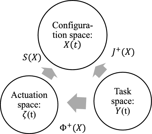
matrices can be found in Appendix C. Using mapping relationship shown in Fig. 5 among the configuration space (
 $X$
), actuation space (
 $\zeta$
) and task space (
 $Y$
), the following state-space forms are derived:
Mapping relations for the actuation space, the configuration space and the task space.

 $\dot{X}=S\zeta$
,
 $\dot{\zeta }=-\overline{M}^{-1}\!\left(\overline{C}\zeta +\overline{G}\right)+\overline{M}^{-1}\!\left(\overline{E}\tau -\overline{A}F_{sf}\right)$
,
 $\dot{Y}=\unicode{x03C6} \zeta$
.
Let us introduce a new system state variables
 $Z=\left[X^{T},\zeta ^{T}, Y^{T}\right]$
and now the state-space form can be obtained as follows:
 \begin{equation}\dot{Z} = \left[\begin{array}{c} \dot{X}\\[4pt] \dot{\zeta}\\[4pt] \dot{Y} \end{array}\right] = \left[\begin{array}{c} S\zeta \\[4pt] V\\[4pt] \unicode{x03C6} \zeta \end{array}\right]+\left[\begin{array}{c} 0\\[4pt] \overline{M}^{-1}\overline{E}\\[4pt] 0 \end{array}\right]\!\tau,\end{equation}
where,
 $V=-\overline{M}^{-1}\!\left(\overline{C}\zeta +\overline{G}\right)-\overline{M}^{-1}\overline{A}F_{sf}$
is a nonlinear function.
4. Controller design
Further, the above derived state-space mathematical form in Eq. (25) can be simplified by applying the following nonlinear feedback approach [Reference Yamamoto and Yun33, Reference Fierro and Lewis34, Reference Yun and Yamamoto35],
 \begin{equation}\tau =\left(\overline{M}^{-1}\overline{E}\right)^{+}(\beta -V),\end{equation}
where, + symbol indicates generalized matrix inverse.
The state-space vector is further expressed by substituting Eq. (26) in Eq. (25). Thus, the simplified state-space form for trajectory simulation is described as:
 \begin{equation}\dot{Z} = \left[\begin{array}{c} S\\[3pt] 0\\[3pt] \unicode{x03C6} \end{array}\right]\zeta +\left[\begin{array}{c} 0\\[3pt] I\\[3pt] 0 \end{array}\right]\beta.\end{equation}
The input/output relation can be found by taking the second derivative of the output variable Y shown in Eq. (23), where the variable
 $\beta$
is chosen as a control input to the nonlinear feedback system. The
 $\beta$
value used in the model-based control law (Eq. 26) has been determined from the PID control law (Eqs. (28) and (29)),
 \begin{equation}\beta =\unicode{x03C6} ^{+}(X)\left(\ddot{Y}-\dot{\unicode{x03C6} }(X)\zeta \right),\end{equation}
where,
 $\ddot{Y}=\ddot{Y}_{d}+K_{p}E(t)+K_{d}\dot{E}(t)+K_{i}\int E(t)dt$
and error equation becomes:
 \begin{equation}\ddot{E}(t)+K_{p}E(t)+K_{d}\dot{E}(t)+K_{i}{\int }_{0}^{t}E(t)dt=0.\end{equation}
Where, diagonal matrices
 $K_{p}$
,
 $K_{d}$
, and
 $K_{i}$
are the proportional, derivatives and integral gains,
 $E(t)=(Y_{d}-Y$
),
 $\dot{E}(t)$
,
 $\ddot{E}(t)$
are trajectory errors in position, velocity, and acceleration, respectively.
 $Y$
is the actual trajectory obtained from the motion simulation while, the desired trajectory
 $Y_{d}$
is obtained from the robot motion planning. Particle swarm optimization (PSO) algorithm has been used to auto-tuned the PID controller gain parameters and discussed in the next sub-section.
4.1. Motion planning and PSO algorithms
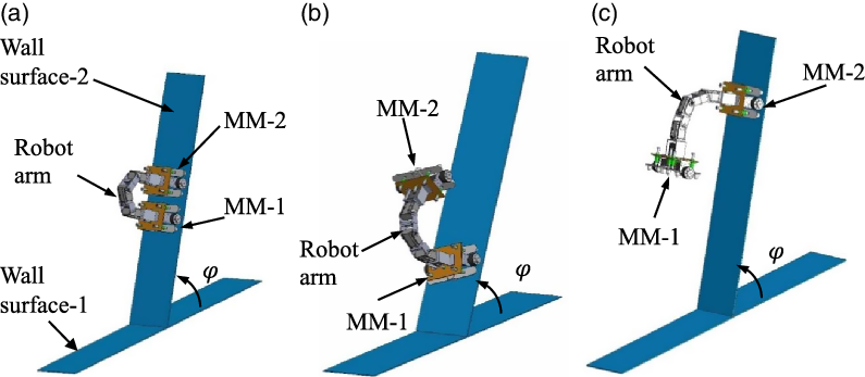
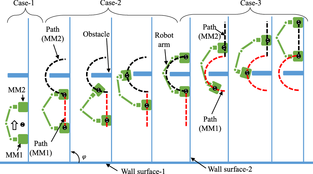
In Fig. 6, the wheel actuation of two mobile modules is done by independent control of motorized magnetic wheel mechanisms. The robot can have different gait actuation such as inchworm, flipping over and swinging around for path planning. However, the inchworm gait actuation of the robot is considered because of its simple body structure, and it uses a simple gait pattern to move on a complex surface. The direction control of the motorized switching mechanism is used to attach and detach the magnetic wheels of the modules (MM 1 & 2) while using arm locomotion, like lift and drop of head and tail of the inchworm (Fig. 6(b–c)) on the vertical wall surface.
Steps for motion gait pattern planning of the robot using wheel and arm locomotion (a) robot uses combined wheel mode of MM 1 & 2, (b) robot uses wheel mode of MM 1 and arm mode, (c) robot uses arm mode and wheel mode of MM 2.

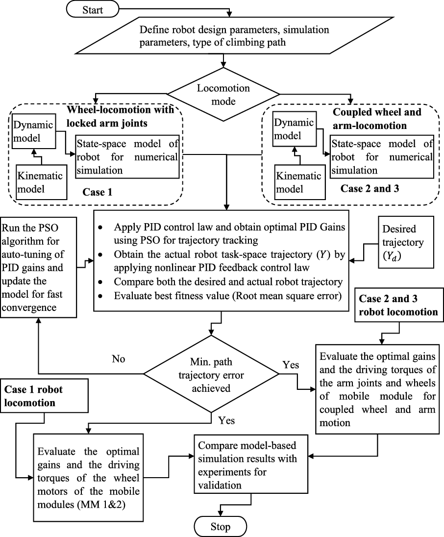
A typical environment made of the two-wall surfaces shown in Fig. 6 has been considered for the combined locomotion simulation of the proposed robot. The first Case described in Fig. 6(a) of robot will generally be preferred for climbing on a plain vertical wall by using combined wheel locomotion mode of MM1&2 while locking all joint motions of the robot arm. The Case-2 locomotion mode shown in Fig. 6(b) uses wheel mode of MM1 and robot arm locomotion mode for effective positioning the MM2, where the Case-3 locomotion mode shown in Fig. 6(c) uses wheel mode of MM2 and robot arm locomotion mode for effective positioning the MM1. These motions can be effectively used while obstacle avoidance and wall transitions. The developed algorithms in MATLAB for wheel and arm locomotion mode of the robot using model-based PID control strategies are shown in the flow diagram (Fig. 7). The
 $\beta$
value used in the model-based control law (Eq. (28)) has been determined from the PID control law. The auto-tuning of the control parameters is performed by the meta-heuristic particle swarm optimization (PSO) technique implemented with the robot motion control algorithm [Reference Kennedy and Eberhart36]. The literature suggests PSO algorithm for motion planning and controller design, and it outperforms compared to other swarm based and evolutionary algorithms [Reference Fister, Fister, Fister and Šafarič37]. The aim of the PSO technique is to obtain optimal control parameters by minimizing the fitness function which is described as root mean squared error (RMSE) of the robot trajectory [Reference Bisht, Pathak and Panigrahi38]. A detailed description of PSO and its variants for autotuning the control parameters can be found elsewhere [Reference Bisht, Pathak and Panigrahi38, Reference Samanta and Nataraj39].
Flow diagram of the developed algorithms for wheel and arm locomotion mode of the robot using model-based PID-PSO control strategies.

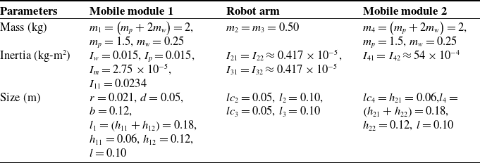
The robot parameters used in the wheel and arm motion trajectory simulations are shown in Table III and evaluated using the robot CAD model by choosing appropriate materials. Further, the robot design parameters in Table III are elaborated in Appendix A.
Design parameters of the wall-climbing robot for wheel and arm motion simulation.

From Eq. (27),
 $Y$
is the actual trajectory obtained from the simulation while
 $Y_{d}$
is the desired trajectory obtained from the robot motion planning for wall-climbing during obstacle avoidance. The desired trajectory for Case-1 robot motion is very straightforward. However, the desired trajectory for the obstacle avoidance for Case-2 robot motion in Fig. 8 for time interval
 $t=[0\ \ 10]$
sec can be represented in Eq. (30), where the CG of MM-1 (
 $x_{c1}y_{c1}z_{c1}$
) follows the straight-line path while the CG of MM-2 (
 $x_{c2}y_{c2}z_{c2}$
) follows the semi-elliptical path defined as:
 \begin{equation}Y_{d}=\left[\begin{array}{c} x_{c1}\\[3pt] y_{c1}\\[3pt] z_{c1}\\[3pt] x_{c2}\\[3pt] y_{c2}\\[3pt] z_{c1}\end{array}\right]=\left[\begin{array}{c} \cos \varphi \!\left(0.016t\right)-\sin \varphi \!\left(h_{11}\right)\\[3pt] 0\\[3pt] \sin \varphi \!\left(0.016t\right)+\cos \varphi \!\left(h_{11}\right)\\[3pt] \cos \varphi \!\left(0.24-0.08\text{cos} \!\left(\dfrac{\pi }{10}t\right)\right)-\sin \varphi \!\left(h_{11}+0.1\text{sin} \!\left(\dfrac{\pi }{10}t\right)\right)\\[7pt] 0\\[3pt] \sin \varphi \!\left(0.24-0.08\text{cos} \!\left(\dfrac{\pi }{10}t\right)\right)-\cos \varphi \!\left(h_{11}+0.1\text{sin} \!\left(\dfrac{\pi }{10}t\right)\right) \end{array}\right].\end{equation}
Robot motion planning for wall-climbing while an obstacle avoidance using wheel and arm locomotion (
 $\varphi = \text{90}^{\circ}$
).

The desired trajectory for the obstacle avoidance for Case-3 robot motion in Fig. 8 for time interval
 $t=[10\ \ 20]$
sec can be represented in Eq. (31), where the CG of MM-1 follows the semi-elliptical path while the CG of MM-2 follows straight-line path defined as:
 \begin{equation}Y_{d}=\left[\begin{array}{c} x_{c1}\\[3pt] y_{c1}\\[3pt] z_{c1}\\[3pt] x_{c2}\\[3pt] y_{c2}\\[3pt] z_{c1} \end{array}\right]=\left[\begin{array}{c} \cos \varphi \left(0.24-0.08\text{cos} \left(\dfrac{\pi }{10}\left(t-10\right)\right)\right)-\sin \varphi \left(h_{11}+0.1\text{sin} \left(\dfrac{\pi }{10}\left(t-10\right)\right)\right)\\[6pt] 0\\[5pt] \sin \varphi \left(0.24-0.08\text{cos} \left(\dfrac{\pi }{10}\left(t-10\right)\right)\right)-\cos \varphi \left(h_{11}+0.1\text{sin} \left(\dfrac{\pi }{10}\left(t-10\right)\right)\right)\\[6pt] \cos \varphi \left(0.16+0.016t\right)-\sin \varphi \left(h_{11}\right)\\[3pt] 0\\[3pt] \sin \varphi \left(0.16+0.016t\right)+\cos \varphi \left(h_{11}\right) \end{array}\right].\end{equation}
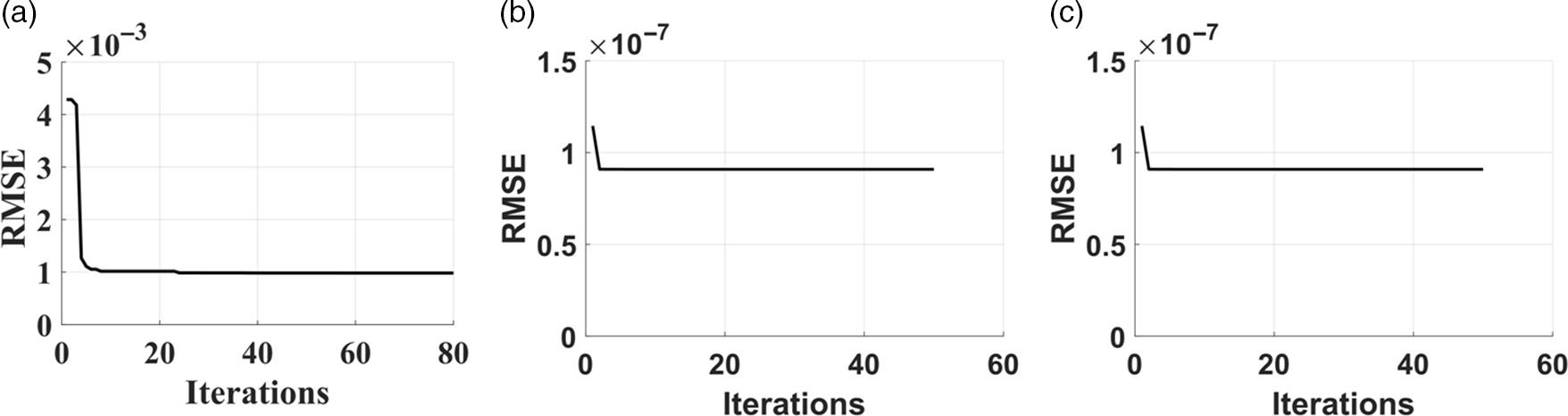
The PSO convergence characteristics have been evaluated before the evaluation of the robot actual trajectory tracking. The above described three cases of robot trajectory have been considered for evaluating the optimal PID gains using PSO. For these three cases, the obtained convergence characteristics (Fig. 9) measured by RMSE show good convergence characteristics. The PSO algorithm for coupled wheel and arm locomotion (Case-2 & 3) requires a higher search range of PID gains for auto-tuning (Table IV) compared to the wheel locomotion of the robot in Case-1.
Convergence characteristics of the developed PID-PSO algorithm used for robot trajectory tracking, (a) Case-1, (b) Case-2, (c) Case-3.

Auto-tuned PID controller parameters using PSO for trajectory tracking.

4.2. Robot arm workspace analysis
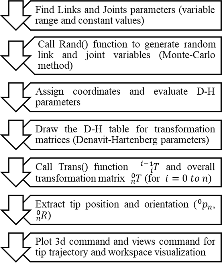
The workspace of the wall-climbing robot is the key to its ability to accomplish the expected task by the robot arm during obstacle avoidance and wall-to-wall transitions. Based on the forward kinematics analysis described in Section 3.1, the Monte-Carlo method is used to analyze the robot arm motion space by generating random numbers of joint variables.
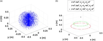
MATLAB algorithm shown in Fig. 10 is developed to simulate the robot arm tip trajectory and workspace of the proposed wall-climbing robot. The robot arm tip-trajectory is performed using the derived kinematic model for the known joint angle configurations of the robot arm. The non-planar workspace is shown in Fig 11 and it uses the design parameters of the robot (Table III). Figure 11(a) shows the workspace and Fig. 11(b) shows the tip-trajectory analysis for the arm reachability. The results indicate that the robot arm tip can reach the maximum height of 0.58 m with a turning diameter of 0.8 m (Fig. 11(b)) when it uses heading angle (
 $\theta =0^{\circ}-360^{\circ}$
) and three known arm joint configurations (
 $\theta _{1},\theta _{2}, \theta _{3}$
). These parameters can be useful for the coupled wheel and arm motion planning, particularly obstacle avoidance and wall-to-wall transitions.
Developed algorithm for workspace analysis of the robot arm.

(a) workspace and (b) tip-trajectory analysis for the arm reachability.

5. Development of combined locomotion based wall-climbing robot
5.1. Prototype of the wall-climbing robot
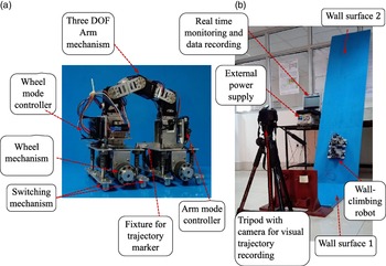
The developed prototype robot (Fig. 12(a)) has been used for the validation of model-based simulation results. The experimental set-up in Fig. 12(b) has been developed for conducting the wheel and arm locomotion trials and experimental measurements of the robot motion along a vertical wall and under obstacle avoidance scenarios. In the robot hardware, DC brushed motors with speed ratings (0-70 rpm) are used for the wheel motion control. However, servo motors with speed ratings (0–229 rpm) are used for the arm motion control. In the control algorithm, the speed of the locomotion (arm and wheel) modes has been programmed, where the speed of arm motors is set to be at 2 rpm, and the wheel motors speed is set to be up to 70 rpm for experimental trials. During the wheel locomotion mode of the robot at 70 rpm of the motor speed, the observed maximum speed of the robot is approximately 9 m/min. The combined wheel and arm locomotion mode has been used during obstacle avoidance and wall transitions only, and the locomotion time depends on the type and size of obstacles.
Combined wheel and arm locomotion trials: (a) Developed autonomous wall-climbing robot. (b) Laboratory set-up for coupled (wheel and arm) locomotion trials.

5.2. Control and communication hardware design and implementation
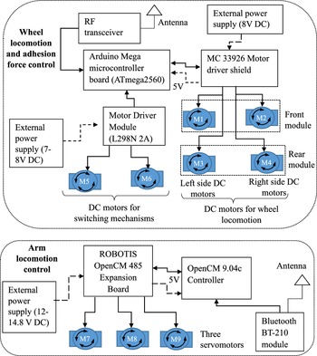
The electronic hardware for wheel locomotion and switching mechanisms are developed using Arduino mega microcontroller board and separate motor drivers. RF transceiver is used for remote communication. Four brushed DC motors (denoted by M1, M2, M3, and M4) are connected to each magnetic wheel to drive the robot on wheel locomotion mode. The DC motors M1 and M2 are connected with the front mobile module, and M3 and M4 are connected with the rear mobile module of the robot (Fig. 13). Two other DC motors M5 and M6 are equipped to actuate the switching mechanism of respective mobile modules (front and rear) to control the magnetic wheel adhesion force. Wireless communication is achieved by interfacing RF (2.4 GHz) transceiver with the respective Arduino boards of the robot and the remote-control station.
Electronics Architecture for wheel locomotion control, wheel adhesion force control and arm locomotion control.

The electronic hardware has been developed using OpenCM9.04c controller with ROBOTIS OpenCM 485 expansion board, Bluetooth module, servo motor connectors for the arm locomotion control. This hardware can be interfaced with the RoboPlus task virtual remote control. The arm-locomotion control command comes from the Bluetooth module (BT-210) via the ROBOTIS mobile software control interface. There are three servomotors (denoted by M7, M8, and M9) that are used with the robot arm locomotion mechanism (Fig 13). These servo motors are attached with arm joint 1, joint 2, and joint 3, respectively and connected serially with the ROBOTIS OpenCM 485 Expansion board. The electronics architecture of the robot for both the wheel and arm locomotion is shown in Fig. 13. Arduino IDE software is used for the development of control algorithm and this algorithm has been implemented with the described electronic hardware for various control strategies.
6. Results and discussion
The dynamic model, simulation strategies, and physical prototype of the wall-climbing robot are coupled with each other for precise validation. The mathematical models of the wall-climbing robot are utilized to analyze and predict its dynamic behavior and sizing of the DC actuators of the robot. Here robot wheel and arm locomotion simulation and experimental investigations have been done and compared with the simulations.
6.1. Robot locomotion trajectory response using simulations and experiments (Case 1)
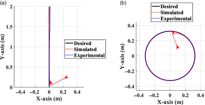
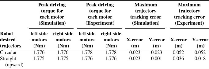
A plain vertical wall climbing can be performed by combing the wheel locomotion of both the mobile modules and restricting the arm joint rotations for greater trajectory tracking accuracy. It is found from the quasi-static force analysis [Reference Bisht, Pathak and Panigrahi26] that the almost vertical wall is most critical for wall-climbing robot, hence, vertical wall trajectory response and corresponding required driving torques have been evaluated for two cases (straight line and circular) and its’ trajectory simulation is shown in Fig. 14 and Table V, respectively.
Trajectory response of wheel locomotion mode of operation of wall-climbing robot on a vertical wall: (a) straight-line motion (b) circular motion, where the arrow indicates initial position and direction of the robot movement.

Driving torque of wall-climbing robot working under wheel locomotion mode on a vertical wall climbing.

Experiments on the wall-climbing robot for Case-1 on a vertical surface have also been performed for straight-line (upward) and circular motion. Where gain parameters (
 $K_{p}\approx 500$
,
 $K_{d}\approx 20$
, and
 $K_{i}\approx 2$
) tuned automatically using PID-PSO have been taken for obtaining the desired level of accuracy in the trajectory response simulation. Based on the driving torque simulation results, four lightweight DC brushed motors (motor stall torque =3.5 nm) for wheel actuation are selected for manufacturing trials of the robot. Further, to compare simulated trajectory, experimental trajectory recorded using video-tracking MATLAB algorithm from the traced video images. These experimental trajectories that is, robot position, velocity, and acceleration, are further substituted in Eq. 15, as derived in Section 3 to get the wheel locomotion driving torques. Torque obtained from the experimental trajectory shows a close comparison with the obtained simulation results (Table V).
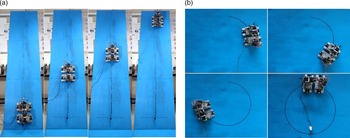
The detailed experimental results of the robot for Case-1 are shown in Fig. 15(a) and (b) for various motion cases on a vertical wall using a laboratory set-up. For working, only on wheel mode of the robot, all the three joints of the arm mechanism are to be locked (
 ${\theta _{1}}=0^{^{\circ}}$
,
 ${\theta _{2}}=0^{^{\circ}}$
and
 ${\theta _{3}}=90^{^{\circ}}$
) to restrict the unnecessary arm movements for greater accuracy in wheel locomotion trajectory tracking. The output of the given input desired trajectory to the robot controller for straight-line and circular motion is shown in Fig. 15(a) and (b), respectively. The robot is perfectly crawling without any mode of failure, that is, sliding, turning, or toppling, and these experimental motions are very close to the simulated trajectory. Hence, it is revealed from the response trajectory and torque (Table V) results that both the simulation and experimental findings show good comparisons and validate the model-based design of the wall-climbing robot working under wheel locomotion mode.
Wheel locomotion experimental trials of the wall-climbing robot: (a) straight-line motion, (b) circular motion on a vertical wall
 $(\varphi \thickapprox 90^{\circ})$
.

6.2. Robot wheel and arm locomotion trajectory response using simulation and experiments (Combined Case 2 & 3)
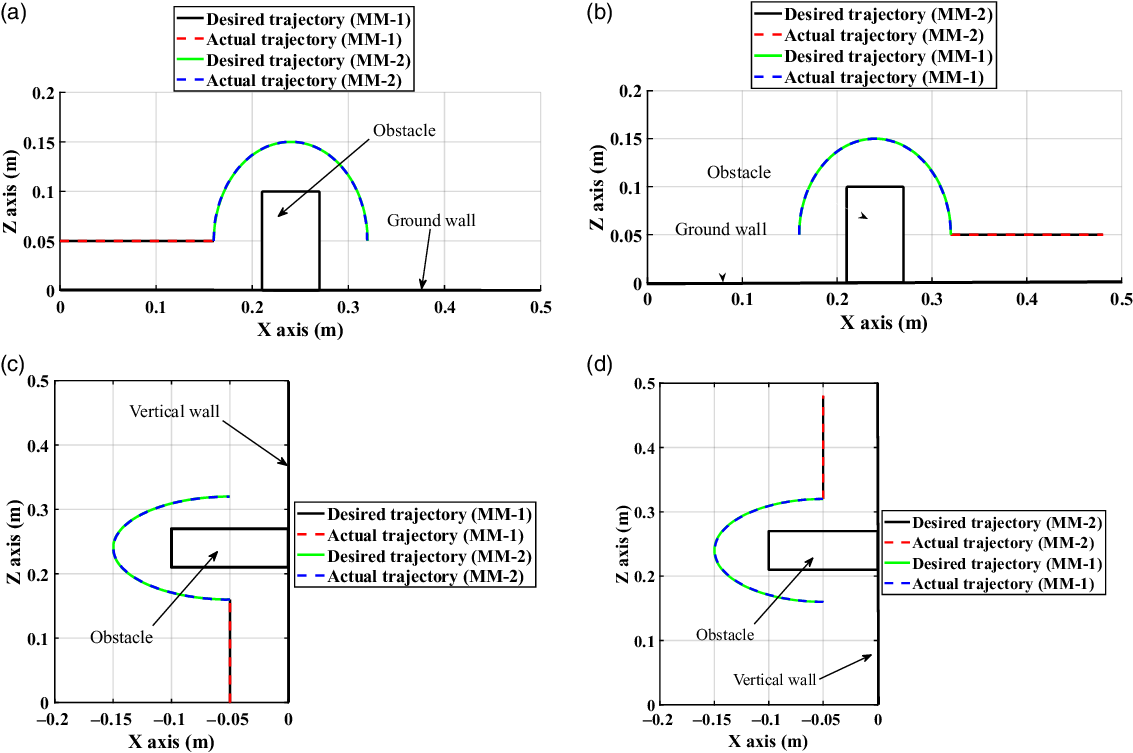
The developed MATLAB algorithms are used to simulate the robot motion on ground/vertical wall to cross over an obstacle. The trajectory tracking simulation results are shown in Fig. 16, where the trajectory paths show the CG location of the MM 1 & 2. In Case 2, an obstacle with height H = 0.10 m and width W = 0.06 m is placed before the wall-climbing robot. In the Case-2 of motion on ground/vertical wall, Fig. 16(a & d) shows the MM-1 of climbing robot is using wheel locomotion on the ground/vertical wall follows straight path and the MM-2 approaches the obstacle by tracking an elliptical path of major (0.10 m) and minor (0.08 m) radius. Considering the height (0.05m) of MM-1 CG from the surface, the maximum reachable height of MM-2 from surface becomes 0.15 m which is sufficient to cross the obstacle of 0.1 m height. After completing the Case2 locomotion, the obstacle comes in between the two mobile modules.
Coupled wheel and arm locomotion trajectory tracking simulation for (a) Case-2 motion on ground wall, (b) Case-3 motion on ground wall, (c) Case-2 motion on vertical wall, (d) Case-3 motion on vertical wall while an obstacle avoidance.

Likewise, in Case-3 of motion simulation shown in Fig. 16(b & d), the MM-2 of the climbing robot moves on a straight path using wheel locomotion while the MM-1 tracks the elliptical path to cross over the obstacle. This shows the complete obstacle avoidance process of a wall-climbing robot using a combined wheel and arm locomotion.
For obstacle avoidance
 $,$
the initial values of robot arm joint variables should be non-singular configuration and these variables are chosen as:
 $\theta _{1}=55^{^{\circ}}$
,
 $\theta _{2}=85^{^{\circ}}$
, and
 $\theta _{3}=50^{^{\circ}}$
for Case-2 robot arm locomotion, and
 $\theta _{1}=10^{^{\circ}}$
,
 $\theta _{2}=15^{^{\circ}}$
, and
 $\theta _{3}=80^{^{\circ}}$
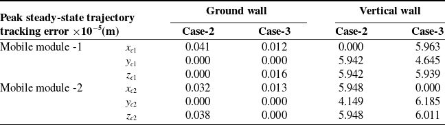
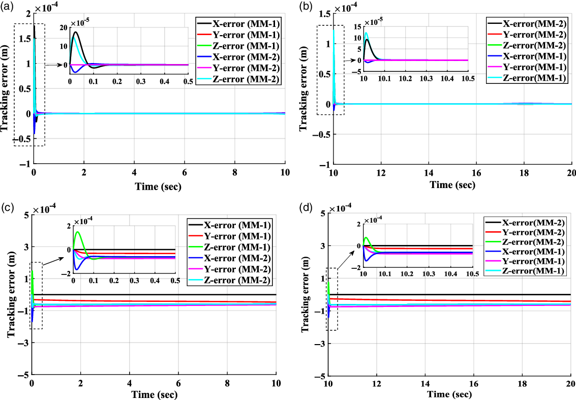
for Case-3 robot arm locomotion, respectively. With the help of path planning shown in Section 4.1, the actual task space simulated CG trajectories of MM-1&2 are closely approaching the desired trajectories, and so, the desired level of accuracy in the trajectory response simulation has been achieved (Fig. 16). The trajectory tracking error has been verified before evaluating the simulated driving torques for robot coupled wheel and arm locomotion. It can be seen from Table VI and Fig. 17 that the trajectory tracking errors are in the order of
 $10^{-5}$
(m) for ground motion and trajectory tracking errors are in the order of
 $10^{-4}$
(m) for vertical wall motion. In Fig. 17, the insets of trajectory error show a clear transient period.
Trajectory tracking errors for Case-2 & 3 robot motions while an obstacle avoidance on ground and vertical wall surface.

Trajectory tracking errors for (a) Case-2 motion on ground wall, (b) Case-3 motion on ground wall, (c) Case-2 motion on vertical wall, (d) Case-3 motion on vertical wall while an obstacle avoidance.

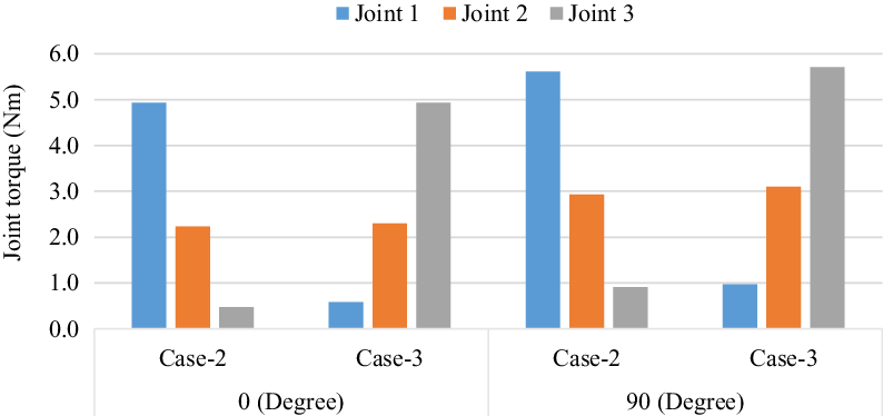
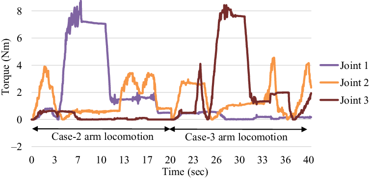
The robot tracking errors on the ground surface are slightly less than those on a vertical wall (Table VI). The driving torque of DC motors required for the wheel and arm locomotion are evaluated using the Case-2&3 robot motion. The motor torques for various cases and different surface inclinations are shown in Fig. 18. The results show the driving torques require more for the vertical wall compared to the ground wall motion. It was found from the simulation that arm joint 1 has maximum torque and arm joint 3 has minimum torque during the Case-2 of robot motion since the mobile module 1 is moving on the wall surface while mobile module 2 is freely turning. In contrast, Joint 3 has maximum torque and joint 1 has minimum torque during the Case-3 of robot motion. The peak torque required at each joint is effectively predicted by performing both the Case-2&3 arm motion simulations of the robot. Otherwise, the required driving torque information only from one-Case may mislead for suitable selection of DC motors.
Simulation results of robot arm joint torque vs wall angle for Case-2&3 locomotion for climbing on ground and vertical wall.

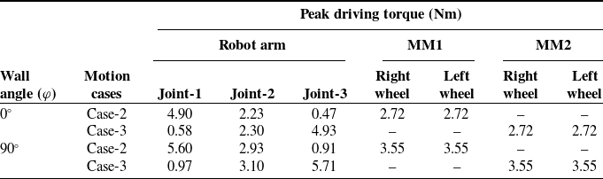
From the simulation, the peak values of driving torque required at each joint of the robot arm for the given specifications of the climbing robot are 4.90, 2.30, and 4.93 nm, when wall angle (
 $\varphi =0^{\circ}$
) and 5.60, 3.10, and 5.71 nm when wall angle (
 $\varphi =90^{\circ}$
) (Table VII). The driving torque for left and right wheel of the mobile modules are 2.72 and 3.55 nm, respectively for the ground and vertical wall climbing respectively (Table VII).
Maximum joint torques for wall climbing while obstacle avoidance using Case-2 and Case-3 for coupled wheel and arm locomotion.

Based on the above simulation results for robot arm, three smart servo motors (Model: Dynamixel MX-106T, stall torque = 10 nm) are selected for laboratory trials of the proposed robot. However, due to compact size and lightweight, DC motors with stall torque 3.5 nm are used in the prototype under wheel locomotion mode. As the wheel motor torque is insufficient for vertical wall with obstacle avoidance against gravity direction, only trials are conducted on an inclined wall surface (45
 $^{\circ}$
).
From the motion simulation strategies of the wall-climbing robot, it is further compared with experimental trials of the developed wall-climbing robot in similar situations using the experimental set-up shown in Fig. 19, where wall angle
 $\varphi =45^{\circ}$
. The experimental joint torques (
 $\tau _{1}, \tau _{2}$
and
 $\tau _{3}$
), as shown in Fig. 20 are obtained by relating the motor torque (
 $K_{t}$
=
 $K_{e}=\frac{V_{peak}}{\omega _{no-load}}$
) constant to the measured motor currents for the three servo joints of the arm mechanism. The values of parameters
 $\omega _{no-load}$
,
 $V_{peak}$
are obtained from the MX-106T (2.0) ROBOTIS e-Manual, and the output data of the Dynamixel motors are recorded using Arduino open-source programming software (IDE) as per the description given in a control table of ROBOTIS e-Manual (Protocol 2.0).
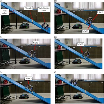
Various steps of climbing strategies using arm mechanism for obstacle avoidance: (a) Combined MM1&2 for wheel locomotion of Case-1, (b) Case-2 arm locomotion (start), (c) Case-2 arm locomotion (finish), (d) Case-3 arm locomotion (start), (e) Case-3 arm locomotion (finish), (f) Combined MM1&2 for wheel locomotion of Case-1 (
 $\phi = 45^{\circ}$
).

Detailed views and steps of robot locomotion strategies can be seen from the video snapshots given in Fig. 19a-f for obstacle avoidance while climbing. It shows the successful deployment of the wall-climbing robot motion using hybrid locomotion, that is, a combination of wheel and arm locomotion modes. In Fig. 19a, the wall-climbing robot shows wheel locomotion mode before reaching near the obstacle. In order to switch from wheel to arm locomotion for obstacle avoidance (Fig. 19b), the front mobile module detaches its magnetic wheels from the inclined wall surface with the help of a switching mechanism and uses couple wheel and arm motion of Case-2. Placing the front robot module on to the inclined wall surface (Fig. 19c) and after the obstacle by robot arm ends the Case-2 scenario. In the next case of robot motion, wheel detachment of the rear robot module using the switching mechanism takes place (Fig. 19d). Next, the robot arm places the rear mobile module on the inclined wall surface just after the obstacle to end the Case-3 (Fig. 19e). Finally, after a successful obstacle avoidance, the wall-climbing robot uses its wheel locomotion mode with locked arm configuration for wall climbing (Fig. 19f).
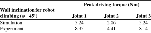
The peak motor driving torque required to the corresponding joints has been evaluated numerically using Eqs. 18 and 19. Simulation results are used to compare the experimental findings given in Fig. 20, and both are compared in Table VIII.
Experimental torque (absolute) of the three servo joints of the arm locomotion mechanism during obstacle avoidance while climbing.

Simulation and experimental comparisons of peak joint torques of servo motors of robot arm during obstacle avoidance while climbing.

It is revealed from Table VIII that both the simulation and experimental findings are in relatively good agreement and validate the model-based design of the wall-climbing robot. The slight high variation in simulation and experimental results is due to the lumped mass model of the robot arm in the dynamic modelling and simulation.
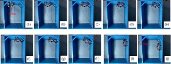
Apart from the above motion trials of the robot for validation of simulations, the proposed wall-climbing robot motion on the ceiling surface and wall transitions has also been performed. The robot motion trials are given in Fig. 21 show ceiling climbing and transitions from the ceiling to the vertical wall surface. The motion trials show that the robot uses wheel locomotion on ceiling surface climbing (Fig. 21a-d). However, combined wheel and arm locomotion are used for ceiling to vertical transitions (Fig. 21e-h). Further, on a vertical surface in the downward direction, it again uses its wheel locomotion (Fig. 21i-j). Simulation and experimental trials suggest that climbing on the ceiling and vertical downward direction requires less driving torque than the vertical upward climbing motion. As evidence from the trials, the robot effectively uses the combination of wheel and arm locomotion according to the wall climbing situations.
Wall-climbing robot motion trials in ceiling and ceiling to vertical wall climbing using laboratory set-up.

The disturbances viz., change in wall thickness, wall surface conditions (friction and roughness), external forces (gravity and wheel adhesion) are among the few parameters which can certainly alter or degrade the performance of the wall-climbing robot maneuvering without considering any disturbances in the present study [Reference Espinoza, de Oliveira, de Arruda and Junior40]. Further, disturbance in wheel adhesion force and friction between wheel and wall surface has been studied using simulation for the desired trajectory tracking. For three cases of change in wheel adhesion force are assumed to be ±5%, ±10% and ±15% and a corresponding change in wheel driving torques are ±3.54%, ±7.09% and ±10.64%, respectively. Similarly, for three cases of change in the coefficient of friction, the change in wheel driving torques are ±3.83%, ±7.65% and ±11.48%, respectively. The study suggests that disturbance due to surface condition influences the dynamic behavior more than the change in wheel adhesion force. The disturbance less than
 $\pm$
5% for both the parameters results in negligible influence on the performance of the designed robot. Similarly, the influence of surface friction and wheel adhesion disturbances have been observed during experiments.
7. Conclusion
This paper presents the dynamics and control strategies of a wheel and arm locomotion-based wall-climbing robot. Generalized mathematical models have been formulated for coupled wheel and arm locomotion, and algorithms have been developed for further numerical simulations using MATLAB. The robot motion trajectories are performed by model-based PID control along with autotuning of gain parameters using the PSO algorithm. The simulation studies for various coupled wheel and arm locomotion confirm that the actual trajectories are closely approaching the desired trajectories for a given robot position on the wall. The robot trajectory tracking errors on the ground surface is in the order of
 $10^{-5}$
m. which is less than the robot tracking errors on a vertical wall which is in the order of
 $10^{-4}$
m. From simulation studies, it is observed that wheel locomotion mode (Case-1) requires peak motor torque at each drive wheel that is, about
 $1.77$
Nm. The required peak motor torque at each drive wheel is about
 $3.55$
Nm for Case 2&3 of coupled wheel and arm locomotion which is about twice the wheel locomotion mode. Similarly, the maximum torque required for robot arm motion is about 6.0, 4.0, and 6.0 nm at three servo joints viz. joints
 $1$
,
 $2,$
and
 $3$
, respectively. Experimental trials of the wall-climbing robot on a vertical wall, ceiling, wall transitions, and during obstacle avoidance have been performed successfully. Both the simulation and experimental predictions show good comparisons and validate the model-based design of the wall-climbing robot working under the coupled wheel and arm locomotion modes. In the current study, the arm actuation is performed by inchworm type gait planning. However, there is a need to investigate energy efficiency in various modes of gait planning of the robot arm, such as inchworm, swinging around, and flipping over locomotion modes.
Disclosure Statements
Acknowledgments
The authors would like to thank Director, CSIR-Central Building Research Institute, Roorkee for guidance, support, and encouragement.
Financial support
The research work is financially supported by R&D project: OLP-0423 of CSIR-Central Building Research Institute, Roorkee, India.
Competing interests declaration
The authors declare no competing interests regarding the publication of this paper.
Availability of data and materials
The authors confirm that the data supporting the findings of this study are available within the article. The MATLAB codings and control algorithms that support the findings of this study are available to the authors.
Authors contributions
R. S. Bisht: Mathematical modelling, Algorithms, Simulations, Experiments, Writing-original draft of the manuscript.
P. M. Pathak: Conceptualization, Methodology, Reviewing and Editing, Supervision.
S. K. Panigrahi: Conceptualization, Experiments, Reviewing and Editing, Supervision.
Appendix A
A1.1. Abbreviations
The following abbreviations are used for expressing mathematical derivations in simplified form.
 $\text{s} \varphi =\sin \varphi$
,
 $\text{s} \theta =\sin \theta$
,
 $\text{s}_{1}=\sin \theta _{1}$
,
 $\text{s}_{2}=\sin \theta _{2}$
,
 $\text{s}_{3}=\sin \theta _{3}$
,
 $\text{s}_{11}=\sin \left(2\theta _{1}\right)$
,
 $\text{s}_{12}=\sin \left(\theta _{1}+\theta _{2}\right)$
,
 $\text{s}_{23}=\sin \left(\theta _{2}+\theta _{3}\right)$
,
 $\text{s}_{123}=\sin \left(\theta _{1}+\theta _{2}+\theta _{3}\right)$
,
 $\text{s}_{112}=\sin \left(2\theta _{1}+\theta _{2}\right)$
,
 $\text{s}_{1122}=\sin \left(2\theta _{1}+2\theta _{2}\right)$
,
 $\text{s}_{1123}=\sin \left(2\theta _{1}+\theta _{2}+\theta _{3}\right)$
,
 $\text{s}_{11223}=\sin \left(2\theta _{1}+2\theta _{2}+\theta _{3}\right)$
,
 $\text{s}_{112233}=\sin \left(2\theta _{1}+2\theta _{2}+2\theta _{3}\right)$
,
 $\text{s}_{\theta 1}=\sin \left(\theta +\theta _{1}\right)$
,
 $\text{s}_{1\theta }=\sin \left(\theta -\theta _{1}\right)$
,
 $\text{s}_{\theta 12}=\sin \left(\theta +\theta _{1}+\theta _{2}\right)$
,
 $\text{s}_{12\theta }=\sin \left(\theta -\theta _{1}-\theta _{2}\right)$
,
 $\text{s}_{\theta 123}=\sin \left(\theta +\theta _{1}+\theta _{2}+\theta _{3}\right)$
,
 $\text{s}_{123\theta }=\sin \left(\theta -\theta _{1}-\theta _{2}-\theta _{3}\right)$
.
 $\text{c} \varphi =\cos \varphi$
,
 $\text{c} \theta =\cos \theta$
,
 $\text{c}_{1}=\cos \theta _{1}$
,
 $\text{c}_{2}=\cos \theta _{2}$
,
 $\text{c}_{3}=\cos \theta _{3}$
,
 $\text{c}_{11}=\cos \left(2\theta _{1}\right)$
,
 $\text{c}_{12}=\cos \left(\theta _{1}+\theta _{2}\right)$
,
 $\text{c}_{23}=\cos \left(\theta _{2}+\theta _{3}\right)$
,
 $\text{c}_{123}=\cos \left(\theta _{1}+\theta _{2}+\theta _{3}\right)$
,
 $\text{c}_{112}=\cos \left(2\theta _{1}+\theta _{2}\right)$
,
 $\text{c}_{1122}=\cos \left(2\theta _{1}+2\theta _{2}\right)$
,
 $\text{c}_{1123}=\cos \left(2\theta _{1}+\theta _{2}+\theta _{3}\right)$
,
 $\text{c}_{11223}=\cos \left(2\theta _{1}+2\theta _{2}+\theta _{3}\right)$
,
 $\text{c}_{112233}=\cos \left(2\theta _{1}+2\theta _{2}+2\theta _{3}\right)$
,
 $c_{\theta 1}=\cos \left(\theta +\theta _{1}\right)$
,
 $\text{c}_{1\theta }=\cos \left(\theta -\theta _{1}\right)$
,
 $\text{c}_{\theta 12}=\cos \left(\theta +\theta _{1}+\theta _{2}\right)$
,
 $\text{c}_{12\theta }=\cos \left(\theta -\theta _{1}-\theta _{2}\right)$
,
 $\text{c}_{\theta 123}=\cos \left(\theta +\theta _{1}+\theta _{2}+\theta _{3}\right)$
,
 $\text{c}_{123\theta }=\cos \left(\theta -\theta _{1}-\theta _{2}-\theta _{3}\right)$
.
A1.2. Expression of kinetic energy:
The net kinetic energy is given for the Case-2 of robot motion described in Section 3.2.
 \begin{align*} K\big(X,\dot{X}\big) = & 0.5m_{1}\big({\dot{x}}_{c}^{2} +{\dot{y}}_{c}^{2}\big)+m_{2}\big(0.5\big({\dot{x}}_{c}^{2}+{\dot{y}}_{c}^{2}\big)-\text{c} \theta \text{s}_{1}\dot{x}_{c}\dot{\theta _{1}}l_{c2}-\text{c}_{1}\text{s} \theta \dot{\theta }\dot{x}_{c}l_{c2} +\text{c} \theta \text{c}_{1}\dot{\theta }\dot{y}_{c}l_{c2}-\text{s}_{1}\text{s} \theta \dot{\theta _{1}}\dot{y}_{c}l_{c2}\\[4pt]& +0.5(\text{c}_{1})^{2}\dot{\theta ^{2}}{l}_{c2}^{2}+0.5\big(\dot{\theta _{1}}^{2}{l}_{c2}^{2}\big)\big)+m_{3}\big(0.5\big({\dot{x}}_{c}^{2}+{\dot{y}}_{c}^{2}\big)+\text{c}_{1}\text{c}_{12} \dot{\theta _{1}}^{2}l_{2}l_{c3}-\text{c} \theta \text{s}_{1}\dot{x}_{c}\dot{\theta _{1}}l_{2}-\text{c} \theta \text{s}_{12} \dot{x}_{c}\dot{\theta _{1}}l_{c3}\\[4pt]& -\text{c} \theta \text{s}_{12} \dot{x}_{c}\dot{\theta _{2}}l_{c3}-\text{c}_{1}\text{s} \theta \dot{x}_{c} \dot{\theta }l_{2}-\text{s} \theta \text{c}_{12} \dot{x}_{c} \dot{\theta }l_{c3}+\text{s}_{1}\text{s}_{12} \dot{\theta _{1}}^{2}l_{2}l_{c3}+\text{c}_{1}\text{c}_{12} \dot{\theta }^{2}l_{2}l_{c3}+\text{c} \theta \text{c}_{1} \dot{y}_{c} \dot{\theta }l_{2}\\[4pt]& +\text{c} \theta \text{c}_{12} \dot{y}_{c}\dot{\theta }l_{c3}-\text{s} \theta \text{s}_{1}\dot{y}_{c}\dot{\theta _{1}}l_{2}-\text{s} \theta \text{s}_{12} \dot{y}_{c}\dot{\theta _{1}}l_{c3}-\text{s} \theta \text{s}_{12} \dot{y}_{c}\dot{\theta _{2}}l_{c3}+\text{c}_{1} \text{c}_{12}\dot{\theta _{1}}l_{2}\dot{\theta _{2}}l_{c3}+\text{s}_{1} \text{s}_{12}\dot{\theta _{1}}l_{2}\dot{\theta _{2}}l_{c3}\\[4pt]& +0.5\Big(\dot{\theta _{1}}^{2}{l_{2}}^{2}\Big)+0.5\Big(\dot{\theta _{1}}^{2}{l}_{c3}^{2}\Big)+0.5\Big(\dot{\theta _{2}}^{2}{l}_{c3}^{2}\Big)+\dot{\theta _{1}}\dot{\theta _{2}}{l}_{c3}^{2}+0.5(\text{c}_{1})^{2}\dot{\theta ^{2}}{l}_{2}^{2}+0.5\big(\text{c}_{12}\big)^{2}\dot{\theta ^{2}}{l}_{c3}^{2}\Big)\\[4pt]& +0.5m_{4}\Big(\Big(\text{c} \varphi \dot{x}_{c}+\big(l_{2}\big({-}\text{c} \theta \text{s}_{1}\dot{\theta _{1}}-\text{c}_{1}\text{s} \theta \dot{\theta }\big)+l_{3}\big({-}\text{c} \theta \text{s}_{12} \big(\dot{\theta _{1}}+\dot{\theta _{2}}\big)-\text{c}_{12}\text{s} \theta \dot{\theta }\big)\\[4pt]& +l_{c4}\big({-}\text{c} \theta \text{s}_{123}\big(\dot{\theta _{1}}+\dot{\theta _{2}}+\dot{\theta _{3}}\big)-\text{s} \theta \text{c}_{123}\dot{\theta }\big)\big)\text{c} \varphi -\text{s} \varphi \big(\big(l_{2}\text{c}_{1}\dot{\theta _{1}}+l_{3}\text{c}_{12}\big(\dot{\theta _{1}}+\dot{\theta _{2}}\big)\\[4pt]& +\text{c}_{123}\big(\dot{\theta _{1}}+\dot{\theta _{2}}+\dot{\theta _{3}}\big)\big)\big)^{2}+\big(\dot{y}_{c}+l_{2}\big({-}\text{s} \theta \text{s}_{1}\dot{\theta _{1}}+\text{c} \theta \text{c}_{1}\dot{\theta }\big)+l_{3}\big({-}\text{s} \theta \text{s}_{12}\dot{\big(\theta _{1}}+\dot{\theta _{2}}\big)+\text{c} \theta \text{c}_{12}\dot{\theta }\big)\\[4pt]& +l_{c4}\big({-}\text{s} \theta \text{s}_{123}\big(\dot{\theta _{1}}+\dot{\theta _{2}}+\dot{\theta _{3}}\big)+\text{c} \theta \text{c}_{123}\dot{\theta }\big)\big)^{2}+\big(\text{s} \varphi \dot{x}_{c}\big(l_{2}\big({-}\text{c} \theta \text{s}_{1}\dot{\theta _{1}}-\text{s} \theta \text{c}_{1}\dot{\theta }\big)\\[4pt]& +l_{3}\big({-}\text{c} \theta \text{s}_{12}\big(\dot{\theta _{1}}+\dot{\theta _{2}}\big)-\text{s} \theta \text{c}_{12}\dot{\theta }\big)+l_{c4}\big({-}\text{c} \theta \text{s}_{123}\big(\dot{\theta _{1}}+\dot{\theta _{2}}+\dot{\theta _{3}}\big)-\text{s} \theta \text{c}_{123}\dot{\theta }\big)\big)s\varphi\\[4pt]& +\big(l_{2}\text{c}_{1}\dot{\theta _{1}}+l_{3}\text{c}_{12}\big(\dot{\theta _{1}}+\dot{\theta _{2}}\big)+l_{c4}\text{c}_{123}\big(\dot{\theta _{1}}+\dot{\theta _{2}}+\dot{\theta _{3}}\big)\big)c\varphi \big)^{2}\Big)+0.5\Big(I_{11}\theta ^{2}+I_{w}\Big(\dot{\theta _{l}}^{2}+\dot{\theta _{r}}^{2}\Big)+I_{21}\dot{\theta }^{2}\\[4pt]& +I_{22}\dot{\theta _{1}}^{2}+I_{31}\dot{\theta }^{2}+I_{32}\big(\dot{\theta }_{1}+\dot{\theta }_{2}\big)^{2}+I_{41}\dot{\theta }^{2}+I_{42}\big(\dot{\theta }_{1}+\dot{\theta }_{2}+\dot{\theta }_{3}\big)^{2}\Big)+2\text{s} \theta d \dot{\theta }\dot{x}_{c}m_{w}-2c \theta d \dot{\theta }\dot{y}_{c}m_{w} \end{align*}
A1.3. Expression of potential energy:
The net potential energy is given for the Case-2 of robot motion described in Section 3.2.
 \begin{align*} U(X) = & m_{1}g(x_{c}\text{s} \varphi +h_{11}\text{c} \varphi )+m_{2}g(x_{c}\text{s} \varphi +h_{11}\text{c} \varphi +l_{c2}\text{c}_{1}\text{c} \theta \text{s} \varphi +(l_{c2}\,\text{s}_{1}+h_{12})\text{c} \varphi )\\[5pt]& +m_{3}g(x_{c}\text{s} \varphi ++h_{11}\text{c} \varphi +(l_{2}\text{c}_{1}\text{c} \theta +l_{c3}\text{c}_{12}\text{c} \theta )\text{s} \varphi +(l_{2}\,\text{s}_{1}+l_{c3}\,\text{s}_{12}+h_{12})\text{c} \varphi )\\[5pt]& +m_{4}g\left(\begin{array}{c} x_{c}\text{s} \varphi +h_{11}\text{c} \varphi +\big(l_{2}\text{c}_{1}\text{c} \theta +l_{3}\text{c}_{12}\text{c} \theta +l_{c4}\text{c}_{123}\text{c} \theta \big)\text{s} \varphi \\[5pt] \big(h_{12}+l_{2}\,\text{s}_{1}+l_{3}\,\text{s}_{12}+l_{c4}\,\text{s}_{123}\big)\text{c} \varphi \end{array}\right)\\[2pt]& +m_{w}g({-}d\text{c} \theta +b\text{s} \theta )\text{s} \varphi -m_{w}g(d\text{c} \theta +b\text{s} \theta )\text{s} \varphi \end{align*}
Where used terms in kinetic energy and potential energy are expressed as follows. The physical properties are defined as:
 $m_{p}$
is mass of the mobile module platform without wheels,
 $m_{w}$
is mass of the magnetic wheel,
 $m_{1}=\left(m_{p}+2m_{w}\right)$
is mass of the mobile module 1,
 $m_{2}$
is mass of the robot arm link 1,
 $m_{3}$
is mass of the robot arm link 2,
 $m_{4}=\left(m_{p}+2m_{w}\right)$
is mass of the mobile module 2.
The inertia properties are defined as:
 $I_{m}$
is the moment of inertia of each magnetic-wheel and motor-rotor about the wheel diameter,
 $I_{w}$
is the moment of inertia of each magnetic-wheel and the motor-rotor about the driving wheel axis,
 $I_{p}$
is the moment of inertia of the platform (without magnetic wheels and DC motors) about a vertical axis passes through
 $P_{c}$
, moment of link inertia
 $I_{21}$
,
 $I_{31}$
,
 $I_{41}$
are due to the mobile module heading angle (
 $\theta$
) and moment of link inertia
 $I_{22}$
,
 $I_{32}$
,
 $I_{42}$
are due to the robot arm joint rotations (
 $\theta _{1}, \theta _{2}, \theta _{3}$
), and
 $I_{11}=I_{p}+2I_{m}+2m_{w}(d^{2}+b^{2})$
.
The geometric properties are defined as:
 $l_{1}=\left(h_{11}+h_{12}\right)$
,
 $l_{2}$
,
 $l_{3}$
and
 $l_{4}=\left(h_{21}+h_{22}\right)$
are the respective robot link length,
 $lc_{2}$
,
 $lc_{3}$
,
 $lc_{4}$
are CG distance of link 2, 3 and 4 from the respective robot arm joints (
 $\theta _{1}$
,
 $\theta _{2}$
and
 $\theta _{3}$
).
Appendix B
B1.1. Expression of inertia matrix:
The inertia matrix
 $M(X)\in \mathbb{R}^{n\times n}$
is derived as,
 \begin{equation*}M(X)=\left[\begin{array}{c@{\quad}c@{\quad}c} M_{11} & \cdots & M_{18}\\[4pt] \vdots & \ddots & \vdots \\[4pt] \text{ symmetric} & \cdots & M_{88} \end{array}\right],\end{equation*}
where,
 \begin{align*}M_{11} & = m_{1}+m_{2}+m_{3}+m_{4},\\M_{13}, M_{31} & =\frac{1}{2}m_{2}\big({-}l_{c2}s_{\theta 1}-l_{c2}s_{1\theta }\big)+\frac{1}{2}m_{3}\big({-}l_{2}s_{\theta 1}-l_{2}s_{1\theta }-l_{c3}s_{\theta 12}-l_{c3}s_{12\theta }\big)\\[3pt]& \quad +\frac{1}{2}m_{4}\big({-}l_{2}s_{\theta 1}-l_{2}s_{1\theta }-l_{3} s_{\theta 12}-l_{3}s_{12\theta } -l_{c4}s_{\theta 123}-l_{c4}s_{123\theta }\big)+2\text{s} \theta d m_{w},\\[3pt]M_{16}, M_{61} & =\frac{1}{2}m_{2}\big(l_{c2}s_{1\theta }-l_{c2}s_{\theta 1}\big)+\frac{1}{2}m_{3}\big(l_{2}s_{1\theta }-l_{2}s_{\theta 1}+l_{c3}s_{12\theta }-l_{c3}s_{\theta 12}\big)\\[3pt]& \quad +\frac{1}{2}m_{4}\big(l_{2}s_{1\theta }-l_{2}s_{\theta 1}+l_{3}s_{12\theta }-l_{3}s_{\theta 12}+l_{c4}s_{\theta 123}-l_{c4}s_{123\theta }\big),\\[3pt]M_{17}, M_{71} & =\frac{1}{2}m_{3}\big(l_{c3}s_{12\theta }-l_{c3}s_{\theta 12}\big)+\frac{1}{2}m_{4}\big(l_{3}s_{12\theta }-l_{3}s_{\theta 12}-l_{c4}\,s_{\theta 123}+l_{c4}\,s_{123\theta }\big),\\[3pt]M_{18}, M_{81} & =-\frac{1}{2}m_{4}\big(l_{c4}s_{\theta 123}-l_{c4}s_{123\theta }\big),\\[3pt]M_{22} & = m_{1}+m_{2}+m_{3}+m_{4},\\[3pt]M_{23}, M_{32} & =\frac{1}{2}m_{2}\big(l_{c2}c_{1\theta }+l_{c2}c_{\theta 1}\big)+\frac{1}{2}m_{3}\big(l_{2}c_{1\theta }+l_{2}c_{\theta 1}+l_{c3}c_{12\theta }+l_{c3}c_{\theta 12}\big)+\frac{1}{2}m_{4}\big(l_{2}c_{1\theta }\\[3pt]& \quad +l_{2}c_{\theta 1}+l_{3}c_{12\theta }+l_{3}c_{\theta 12}+l_{c4}c_{\theta 123}+l_{c4}c_{123\theta }\big)-2\text{c} \theta d m_{w},\\[3pt]M_{26}, M_{62} & =\frac{1}{2}m_{2}\big(l_{c2}c_{\theta 1}-l_{c2}c_{1\theta }\big)+\frac{1}{2}m_{3}\big(l_{2}c_{\theta 1} -l_{2}c_{1\theta }+l_{c3}c_{\theta 12}-l_{c3}c_{12\theta }\big)\\[3pt]& \quad +\frac{1}{2}m_{4}\big(l_{2}c_{\theta 1} -l_{2}c_{1\theta }+l_{3}c_{\theta 12}-l_{3}c_{12\theta }+l_{c4}c_{\theta 123}-l_{c4}c_{123\theta }\big),\\[3pt]M_{27}, M_{72} & =\frac{1}{2}m_{3}\big(l_{c3}c_{\theta 12}-l_{c3}c_{12\theta }\big)+\frac{1}{2}m_{4}\big({-}l_{3}c_{12\theta }+l_{3}c_{\theta 12}+l_{c4}c_{\theta 123}-l_{c4}c_{123\theta }\big),\\[3pt]M_{28}, M_{82} & =-\frac{1}{2}m_{4}\big(l_{c4}c_{\theta 123}-l_{c4}c_{123\theta }\big),\\[3pt]M_{33} & =\frac{1}{2}m_{2}{l}_{c2}^{2}\big(1+\text{c}_{11}\big)+\frac{1}{2}m_{3}\big({l}_{2}^{2}+{l}_{c3}^{2}+{l}_{2}^{2}\text{c}_{11}+{l}_{c3}^{2}\text{c}_{1122} +2l_{2}l_{c3}\text{c}_{2}+2l_{2}l_{c3}\text{c}_{112}\big)\\[3pt]& \quad +\frac{1}{2}m_{4}\big({l}_{2}^{2}+{l}_{3}^{2}+{l}_{c4}^{2}+{l}_{2}^{2}\text{c}_{11}+{l}_{3}^{2}\text{c}_{1122}+2l_{2}l_{3}\text{c}_{2}+2l_{3}l_{c4}c_{11223} +2l_{2}l_{3}\text{c}_{112} +2l_{2}l_{c4}c_{1123}+2l_{2}l_{c4}\text{c}_{23}\\& \quad +2l_{3}l_{c4}\text{c}_{3}\big)+\big({\text{I}_{11}}+{\text{I}_{21}}+{\text{I}_{31}}+\text{I}_{41}\big),\\[3pt]M_{66} & =m_{2}{l}_{c2}^{2}+m_{3}\big({l}_{2}^{2}+{l}_{c3}^{2}+2l_{2}l_{{c_{3}}}\text{c}_{2}\big)+m_{4}\big({l}_{2}^{2}+{l}_{3}^{2}+{l}_{c4}^{2}+2l_{2}l_{3}\text{c}_{2}+2l_{c4}l_{3}\text{c}_{3}+2l_{2}l_{c4}\text{c}_{23}\big)\\[3pt]& \quad +\big(I_{22}+I_{32}+I_{42}\big),\\[3pt]M_{67}, M_{76} & =m_{3}\big({l}_{c3}^{2}+l_{2}l_{c3}\text{c}_{2}\big)+m_{4}\big({l}_{3}^{2}+{l}_{c4}^{2}+l_{2}l_{3}\text{c}_{2}+l_{2}l_{c4}\text{c}_{23}+2l_{c4}l_{3}\text{c}_{3}\big)+\big(I_{32}+I_{42}\big),\end{align*}
 \begin{align*}M_{68}, M_{86} & =m_{4}\big({l}_{c4}^{2}+l_{2}l_{c4}\text{c}_{23}+l_{c4}l_{3}\text{c}_{3}\big)+I_{42},\\[3pt]M_{77} & =m_{3}{l}_{c3}^{2}+m_{4}\big({l}_{3}^{2}+{l}_{c4}^{2}+2l_{c4}l_{3}\text{c}_{3}\big)+\big(I_{32}+I_{42}\big),\\[3pt]M_{78}, M_{87} & =m_{4}{l}_{c4}^{2}+m_{4}l_{c4}l_{3}\text{c}_{3}+I_{42},\\[3pt]M_{88} & =m_{4}{l}_{c4}^{2}+I_{42},\\[3pt]M_{12} & =M_{21}=M_{14}=M_{41}=M_{15}=M_{51}=M_{24}=M_{42}=M_{25}=M_{52}=M_{34}=M_{43}=M_{35}=M_{53}\\[3pt]& =M_{36}=M_{63}=M_{37}=M_{73}=M_{38}=M_{83}=M_{44}=M_{45}=M_{54}=M_{46}=M_{64}=M_{47}=M_{74}\\[3pt]& =M_{48}=M_{84}=M_{55}=M_{56}=M_{65}=M_{57}=M_{75}=M_{58}=M_{85}=0.\end{align*}
B1.2. Expression of Coriolis and centripetal force matrix:
 $C\!\left(X,\dot{X}\right)\in \mathbb{R}^{n\times n}$
is the Coriolis and centripetal force matrix. The matrix elements are expressed as,
 \begin{align*}C\!\left(X,\dot{X}\right)=\left[\begin{array}{c@{\quad}c@{\quad}c} c_{11} & \cdots & c_{18}\\[4pt] \vdots & \ddots & \vdots \\[4pt] c_{81} & \cdots & c_{88} \end{array}\right],\end{align*}
where,
 \begin{align*}\text{C}_{11}, \text{C}_{12} & =0,\\[4pt]\text{C}_{13} & =\frac{1}{2}\text{m}_{2}\big(\big(l_{c2}\big({-}c_{\theta 1}-c_{1\theta }\big)\dot{\theta }+l_{c2}\big(c_{1\theta }- c_{\theta 1}\big)\dot{\theta }_{1}\big)\big)+\frac{1}{2}\text{m}_{3}\big(\big({-}l_{c3}c_{12\theta }-l_{2}c_{\theta 1}-l_{2}c_{1\theta } -l_{c3}c_{\theta 12}\big)\dot{\theta }\\[4pt]& \quad +\big(l_{c3}c_{12\theta }-l_{2}c_{\theta 1}+l_{2}c_{1\theta } -l_{c3}c_{\theta 12}\big)\dot{\theta }_{1}+\big({-}l_{c3}c_{\theta 12}+l_{c3}c_{12\theta }\big)\dot{\theta }_{2}\big)+\frac{1}{2}\text{m}_{4}\big({-}\big(l_{3}c_{\theta 12}+l_{3}c_{12\theta }\\[4pt]& \quad +l_{2}c_{\theta 1}+l_{2}c_{1\theta }+l_{c4}c_{\theta 123}+l_{c4}c_{123\theta }\big)\dot{\theta }+\big(l_{3}c_{12\theta } -l_{3}c_{\theta 12}+l_{2}c_{1\theta }-l_{2}c_{\theta 1} +l_{c4}c_{123\theta }-l_{c4}c_{\theta 123}\big)\dot{\theta }_{1}\\[4pt]& \quad +\big(l_{3}c_{12\theta } -l_{3}c_{\theta 12}+l_{c4}c_{123\theta }-l_{c4}c_{\theta 123}\big)\dot{\theta }_{2}+\big(l_{c4}c_{123\theta }-l_{c4}c_{\theta 123}\big)\dot{\theta }_{3}\big)+2\text{m}_{\text{w}} \dot{\theta }\text{d}\text{c} \theta,\\[4pt]\text{C}_{14}, \text{C}_{15} & =0,\\[4pt]\text{C}_{16} & =0.5\big(\big(l_{c2}\dot{\theta }\big({-} c_{\theta 1}+c_{1\theta }\big)-l_{c2}\dot{\theta }_{1}\big(c_{\theta 1}+c_{1\theta }\big)\big)\text{m}_{2}+\big(\big(l_{c3}c_{12\theta }-l_{2}c_{\theta 1}+l_{2}c_{1\theta } -l_{c3}c_{\theta 12}\big)\dot{\theta }\\[4pt]& \quad -\big(l_{c3}c_{12\theta }+l_{2}c_{\theta 1}+l_{2}c_{1\theta } +l_{c3}c_{\theta 12}\big)\dot{\theta }_{1}-\big(l_{c3}c_{\theta 12}+l_{c3}c_{12\theta }\big)\dot{\theta }_{2}\big)\text{m}_{3}+\text{m}_{4}\big(\big({-}l_{3}c_{\theta 12}+l_{3}c_{12\theta } -l_{2}c_{\theta 1}\\[4pt]&\quad +l_{2}c_{1\theta }-l_{c4}c_{\theta 123}+l_{c4}c_{123\theta }\big)\dot{\theta }+\big({-}l_{c3}c_{12\theta }-l_{2}c_{\theta 1}-l_{2}c_{1\theta } -l_{c3}c_{\theta 12}-l_{c4}c_{\theta 123}-l_{c4}c_{123\theta }\big)\dot{\theta }_{1}\\[4pt]& \quad +\big({-}l_{c3}c_{12\theta }-l_{c3}c_{\theta 12}-l_{c4}c_{\theta 123}-l_{c4}c_{123\theta }\big)\dot{\theta }_{2}-\big(l_{c4}c_{\theta 123}+l_{c4}c_{123\theta }\big)\dot{\theta }_{3}\big)\big),\\[4pt]\text{C}_{17} & =0.5[\big(\big(l_{c3} c_{12\theta }-l_{c3}c_{\theta 12}\big)\dot{\theta }+\big({-}l_{c3} c_{12\theta }-l_{c3}c_{\theta 12}\big)\dot{\theta }_{1}+\big({-}l_{c3} c_{12\theta }-l_{c3}c_{\theta 12}\big)\dot{\theta }_{2}\text{m}_{3}\\[4pt]& \quad +\big(\big(l_{3} c_{12\theta }-l_{3}c_{\theta 12} -l_{c4}c_{\theta 123}+l_{c4}c_{123\theta }\big)\dot{\theta }+\big({-}l_{3} c_{12\theta }-l_{3}c_{\theta 12} -l_{c4}c_{\theta 123}-l_{c4}c_{123\theta } \big)\dot{\theta }_{1}\\[4pt]& \quad +\big({-}l_{3} c_{12\theta }-l_{3}c_{\theta 12} -l_{c4}c_{\theta 123}-l_{c4}c_{123\theta }\big)\dot{\theta }_{2}+\big({-}l_{c4}c_{\theta 123}+l_{c4}c_{123\theta }\big)\dot{\theta }_{3}\big)\text{m}_{4}],\\[4pt]\text{C}_{18} & =0.5\big(\big({-}l_{c4}c_{\theta 123}+l_{c4}c_{123\theta }\big)\dot{\theta }+\big({-}l_{c4}c_{\theta 123}-l_{c4}c_{123\theta }\big)\dot{\theta }_{1}+\big({-}l_{c4}c_{\theta 123}-l_{c4}c_{123\theta }\big)\dot{\theta }_{2}\\[4pt]& \quad +\big({-}l_{c4}c_{\theta 123}-l_{c4}c_{123\theta }\big)\dot{\theta }_{3}\big)\text{m}_{4},\\[4pt]\text{C}_{21}, \text{C}_{22} & =0,\\[4pt]\text{C}_{23} & =0.5[\text{m}_{2}\big({-}l_{c2}\big(s_{\theta 1}+s_{1\theta }\big)\dot{\theta }+l_{c2}\big({-} s_{\theta 1}+s_{1\theta }\big)\dot{\theta }_{1}\big)+\text{m}_{3}\big(\big({-}l_{c3}s_{12\theta }-l_{2}s_{\theta 1}-l_{2}s_{1\theta } -l_{c3}\,s_{\theta 12}\big)\dot{\theta }\\[4pt]&\quad +\big(l_{c3}\,s_{12\theta }-l_{2}s_{\theta 1}+l_{2}s_{1\theta } -l_{c3}\,s_{\theta 12}\big)\dot{\theta }_{1}+\big({-}l_{c3}s_{\theta 12}+l_{c3}s_{12\theta }\big)\dot{\theta }_{2}\big)+\text{m}_{4}\big({-}l_{3}s_{\theta 12}-l_{3}s_{12\theta } -l_{2}s_{\theta 1}\end{align*}
 \begin{align*}& \quad -l_{2}s_{1\theta }-l_{c4}\,s_{\theta 123}-l_{c4}\,s_{123\theta }\big)\dot{\theta }+\big({-}l_{3}s_{\theta 12}+l_{3}s_{12\theta } -l_{2}s_{\theta 1}+l_{2}s_{1\theta }-l_{c4}\,s_{\theta 123}+l_{c4}\,s_{123\theta }\big)\dot{\theta }_{1}\\[4pt]& \quad +\big({-}l_{3}s_{\theta 12}+l_{3}s_{12\theta }-l_{c4}\,s_{\theta 123}+l_{c4}\,s_{123\theta }\big)\dot{\theta }_{2}+\big({-}l_{c4}\,s_{\theta 123}+l_{c4}\,s_{123\theta }\big)\dot{\theta }_{3}]+2\text{d}\text{m}_{\text{w}}\dot{\theta }\text{s} \theta,\\[4pt]\text{C}_{24}, \text{C}_{25} & =0,\\[4pt]\text{C}_{26} & =0.5[\text{m}_{2}\big({-}l_{c2}\big(s_{\theta 1}-s_{1\theta }\big)\dot{\theta }-l_{c2}\big(s_{\theta 1}+s_{1\theta }\big)\dot{\theta }_{1}\big)+\text{m}_{3}\big(\big(l_{c3}s_{12\theta }-l_{2}s_{\theta 1}+l_{2}s_{1\theta } -l_{c3}\,s_{\theta 12}\big)\dot{\theta }\\[4pt]& \quad +\big({-}l_{c3}\,s_{12\theta }-l_{2}s_{\theta 1}-l_{2}s_{1\theta } -l_{c3}\,s_{\theta 12}\big)\dot{\theta }_{1}+\big({-}l_{c3}s_{\theta 12}-l_{c3}s_{12\theta }\big)\dot{\theta }_{2}\big)\\[4pt]& \quad +\text{m}_{4}\big({-}l_{3}s_{\theta 12}+l_{3}s_{12\theta } -l_{2}s_{\theta 1}+l_{2}s_{1\theta }-l_{c4}\,s_{\theta 123}+l_{c4}\,s_{123\theta }\big)\dot{\theta }+\big({-}l_{3}s_{\theta 12}-l_{3}s_{12\theta } -l_{2}s_{\theta 1}-l_{2}s_{1\theta }\\[4pt]& \quad -l_{c4}\,s_{\theta 123}-l_{c4}s_{123\theta }\big)\dot{\theta }_{1}+\big({-}l_{3}s_{\theta 12}-l_{3}s_{12\theta }-l_{c4}s_{\theta 123}-l_{c4}\,s_{123\theta }\big)\dot{\theta }_{2}+\big({-}l_{c4}\,s_{\theta 123}-l_{c4}\,s_{123\theta }\big)\dot{\theta }_{3}],\\[4pt]\text{C}_{27} & =0.5[\text{m}_{3}\big(\big(l_{c3}s_{12\theta }-l_{c3}\,s_{\theta 12}\big)\dot{\theta }+\big({-}l_{c3}\,s_{12\theta }-l_{c3}\,s_{\theta 12}\big)\dot{\theta }_{1}+\big({-}l_{c3}s_{\theta 12}-l_{c3}s_{12\theta }\big)\dot{\theta }_{2}\big)\\[4pt]& \quad +\text{m}_{4}\big(\big(l_{3}s_{\theta 12}+l_{3}s_{12\theta }-l_{c4}\,s_{\theta 123}+l_{c4}\,s_{123\theta }\big)\dot{\theta }+\big({-}l_{3}s_{\theta 12}-l_{3}s_{12\theta }-l_{c4}\,s_{\theta 123}-l_{c4}\,s_{123\theta }\big)\dot{\theta }_{1}\\[4pt]& \quad +\big({-}l_{3}s_{\theta 12}-l_{3}s_{12\theta }-l_{c4}\,s_{\theta 123}-l_{c4}\,s_{123\theta }\big)\dot{\theta }_{2}+\big({-}l_{c4}\,s_{\theta 123}-l_{c4}\,s_{123\theta }\big)\dot{\theta }_{3}],\\[4pt]\text{C}_{28} & =0.5\text{m}_{4}\big(\big({-}l_{c4}\,s_{\theta 123}+l_{c4}\,s_{123\theta }\big)\dot{\theta }+\big({-}l_{c4}\,s_{\theta 123}-l_{c4}\,s_{123\theta }\big)\dot{\theta }_{1}+\big({-}l_{c4}\,s_{\theta 123}-l_{c4}\,s_{123\theta }\big)\dot{\theta }_{2}\\[4pt]& \quad +\big({-}l_{c4}\,s_{\theta 123}-l_{c4}\,s_{123\theta }\big)\dot{\theta }_{3}\big),\\[4pt]\text{C}_{31} & =\frac{1}{4}\text{m}_{3}\dot{\theta }_{2}\big(l_{c3}\big({-} \text{s}_{12}+\text{c}_{12\theta }-\text{c}_{\theta 12}+\text{s}_{\theta 12}\big)\big)+\frac{1}{4}\text{m}_{4}\dot{\theta }_{2}\big(l_{3}\big({-} \text{s}_{12}+\text{c}_{12\theta }-\text{c}_{\theta 12}+ \text{s}_{\theta 12}\big)\\[4pt]& \quad +l_{c4}\big({-} \text{s}_{123\theta }+\text{c}_{123\theta }-\text{c}_{\theta 123}+ \text{s}_{\theta 123}\big)\big),\\[4pt]\text{C}_{32} & =0.25\big(\text{m}_{3}\big({-}l_{c3}\text{s}_{\theta 12}+l_{c3}\text{s}_{12\theta }\big)\dot{\theta }_{2}+\big({-}l_{c4}\,\text{s}_{\theta 123}+l_{c4}\,\text{s}_{123\theta } -l_{3}\text{s}_{\theta 12}+l_{3}\text{s}_{12\theta }\big)\dot{\theta }_{3}\,\text{m}_{4}\big),\\[4pt]\text{C}_{33} & =-0.5\big(\text{m}_{2}\big({l}_{c2}^{2}\,\text{s}_{11}\big)\dot{\theta }_{1}\big)+\big(\big({-}l_{2}l_{c3}\,\text{s}_{112}-0.5{l}_{2}^{2}\text{s}_{11}-0.5{l}_{c3}^{2}\text{s}_{1122}\big)\dot{\theta }+\big({-}0.5l_{2}l_{c3}\text{s}_{2}-0.5l_{2}l_{c3}\,\text{s}_{112}\\[4pt]& \quad -0.5{l}_{c3}^{2}\text{s}_{1122}\big)\dot{\theta _{2}\big)}m_{3}+\big(\big({-}l_{2}l_{3}\,\text{s}_{112}-0.5{l}_{2}^{2}s11-0.5{l}_{3}^{2}\,\text{s}_{1122}-0.5{l}_{c4}^{2}\text{s}_{112233} -l_{3}l_{c4}\text{s}_{11223}\\[4pt]& \quad -l_{2}l_{c4}\text{s}_{1123}\big)\dot{\theta _{1}}+\big({-}0.5l_{2}l_{c4}\,\text{s}_{1123}-0.5l_{2}l_{3}\text{s}_{2}-0.5l_{2}l_{3}\,\text{s}_{112}-0.5{l}_{3}^{2}\,\text{s}_{1122} -0.5{l}_{c4}^{2}\text{s}_{112233}\\[4pt]& \quad -l_{3}l_{c4}\text{s}_{112233}-0.5l_{2}l_{c4}\text{s}_{1123}\big)\dot{\theta _{2}}+\big({-}0.5l_{2}l_{c4}\text{s}_{23}-0.5{l}_{c4}^{2}\text{s}_{112233}-0.5l_{3}l_{c4}\text{s}_{11223}-0.5l_{2}l_{c4}\text{s}_{1123}\\[4pt]& \quad -0.5l_{3}l_{c4}\text{s}_{3}\big)\dot{\theta _{3}}\big)m_{4},\\[4pt]\text{C}_{34}, \text{C}_{35} & =0,\\[4pt]\text{C}_{36} & =-0.5{l}_{c2}^{2}\,\text{s}_{11}\dot{\theta }m_{2}+\big({-}l_{2}l_{c3}\,\text{s}_{112}-0.5{l}_{2}^{2}\,\text{s}_{11}-0.5{l}_{c3}^{2}\text{s}_{1122}\big)\dot{\theta }m_{3}+\big({-}l_{2}l_{3}\,\text{s}_{112}-0.5{l}_{2}^{2}\,\text{s}_{11}\\[4pt]& \quad -0.5{l}_{3}^{2}\,\text{s}_{1122}-0.5{l}_{c4}^{2}\text{s}_{112233}-l_{3}l_{c4}\text{s}_{11223}-l_{2}l_{c4}\text{s}_{1123}\big)\dot{\theta }m_{4},\\[4pt]\text{C}_{37} & =\big({-}0.5l_{2}l_{c3}\text{s}_{2}-0.5l_{2}l_{c3}\,\text{s}_{112}-0.5{l}_{c3}^{2}\,\text{s}_{1122}\big)m_{3}\dot{\theta }+\big({-}0.5l_{2}l_{c4}\text{s}_{23}-0.5l_{2}l_{3}\text{s}_{2}-l_{2}l_{3}\,\text{s}_{112}\\[4pt]& \quad -0.5{l}_{3}^{2}\,\text{s}_{1122} -0.5{l}_{c4}^{2}\,\text{s}_{112233}-l_{3}l_{c4}\,\text{s}_{11223}-l_{2}l_{c4}\,\text{s}_{1123}\big)\dot{\theta }m_{4},\\[4pt]\text{C}_{38} & =m_{4}\dot{\theta }\big({-}0.5l_{2}l_{c4}\,\text{s}_{23}-0.5{l}_{c4}^{2}\,\text{s}_{112233}-0.5l_{3}l_{c4}\text{s}_{11223}-0.5l_{2}l_{c4}\text{s}_{1123}-0.5l_{3}l_{c4}\text{s}_{3}\big),\\[4pt]\end{align*}
 $\text{C}_{41} =\text{C}_{42}=\text{C}_{43}=\text{C}_{44}=\text{C}_{45}=\text{C}_{46}=\text{C}_{47}=\text{C}_{48}=\text{C}_{51}=\text{C}_{52}=\text{C}_{53}=\text{C}_{54}=\text{C}_{55}=\text{C}_{56}=\text{C}_{57} =\text{C}_{58}=0,$
 \begin{align*}\text{C}_{61} & =0.25\big(l_{c3}s_{\theta 12}+l_{c3}s_{12\theta }-l_{\text{c}3}c_{\theta 12}-l_{c3}c_{12\theta }\big)\dot{\theta }_{2}\,\text{m}_{3}+\text{m}_{4}\dot{\theta }_{3}0.25\big({-}l_{3}c_{\theta 12}-l_{3}c_{12\theta }+l_{c4}\,s_{\theta 123}+l_{c4}s_{123\theta }\\[4pt]& \quad -l_{c4}c_{\theta 123}-l_{c4}c_{123\theta }+l_{3}s_{\theta 12}+l_{3}s_{12\theta }\big),\\\text{C}_{62} & =0.25\big(\text{m}_{3}\big({-}l_{c3}s_{\theta 12}-l_{c3}s_{12\theta }\big)\dot{\theta }_{2}+\big({-}l_{c4}\,s_{\theta 123}-l_{c4}s_{123\theta } -l_{3}s_{\theta 12}-l_{3}s_{12\theta }\big)\dot{\theta }_{3}\,\text{m}_{4}\big),\end{align*}
 \begin{align*}\text{C}_{63} & =0.5{l}_{c2}^{2}\,\text{s}_{11}\dot{\theta }m_{2}+\big(l_{2}l_{c3}\,\text{s}_{112}+0.5{l}_{2}^{2}\text{s}_{11}+0.5{l}_{c3}^{2}\text{s}_{1122}\big)\dot{\theta }m_{3}+\big(l_{2}l_{3}\,\text{s}_{112}+0.5{l}_{2}^{2}\,\text{s}_{11}+0.5{l}_{3}^{2}\,\text{s}_{1122}\\[4pt]& \quad +0.5{l}_{c4}^{2}\text{s}_{112233}+l_{3}l_{c4}\text{s}_{11223}+l_{2}l_{c4}\text{s}_{1123}\big)\dot{\theta }m_{4},\\[4pt]\text{C}_{64}, \text{C}_{65} & =0,\\[4pt]\text{C}_{66} & =\text{m}_{3}\big({-}l_{2}l_{c3}\text{s}_{2} \big)\dot{\theta }_{2}+\text{m}_{4}\big(\big({-}l_{3}l_{2}\text{s}_{2}-l_{2}l_{c4}\text{s}_{23} \big)\dot{\theta }_{2}+\big({-}l_{3}l_{c4}\text{s}_{3}-l_{2}l_{c4}\text{s}_{23} \big)\dot{\theta }_{3}\big),\\[4pt]\text{C}_{67} & =\text{m}_{3}\big(\hbox{-}l_{2}l_{c3}\text{s}_{2}\dot{\theta }_{1}-l_{2}l_{c3}\text{s}_{2}\dot{\theta }_{2}\big)+\text{m}_{4}\big(\big(l_{2}l_{3} \text{s}_{2}-l_{2}l_{c4}\text{s}_{23} \big)\dot{\theta }_{1}+\big({-}l_{2}l_{3} \text{s}_{2}-l_{2}l_{c4}\text{s}_{23} \big)\dot{\theta }_{2}\big.\\[4pt]&\big. +\big({-}l_{3}l_{c4}\text{s}_{3}-l_{2}l_{c4}\text{s}_{23} \big)\dot{\theta }_{3}\big),\\[4pt]\text{C}_{68} & = \text{m}_{4}\big(\big({-}l_{3}l_{c4}\text{s}_{3}-l_{2}l_{c4}\text{s}_{23}\big)\dot{\theta }_{1}+\big({-}l_{3}l_{{\text{c}_{4}}}\text{s}_{3}-l_{2}l_{c4}\text{s}_{23} \big)\dot{\theta }_{2}+\big({-l_{3}l_{c4}\text{s}_{3}-l_{2}l_{c4}\text{s}_{23}}\big)\dot{\theta }_{3} \big),\\[4pt]& \quad \big({-}l_{3}l_{c4}\text{s}_{3}-l_{2}l_{c4}\text{s}_{23}\big)\dot{\theta }_{1} + \big({-}l_{3}l_{{\text{c}_{4}}}\text{s}_{3}-l_{2}l_{c4}\text{s} 23\big)\dot{\theta }_{2} + \big({-}l_{3}l_{c4}\text{s}_{3}-l_{2}l_{c4}\text{s}_{23} \big)\dot{\theta }_{3}\big),\\[4pt]\text{C}_{71} & =\big(0.25\dot{\theta }\big({-}l_{c3}s_{\theta 12}+l_{c3}s_{12\theta }+l_{c3}c_{\theta 12}-l_{c3}c_{12\theta }\big)+0.25\dot{\theta }_{1}\big({-}l_{c3}s_{\theta 12}-l_{c3}s_{12\theta }+l_{c3}c_{\theta 12}+l_{c3}c_{12\theta }\big)\big)\text{m}_{3}\\[4pt]& \quad +\big(0.25\dot{\theta }\big({-}l_{3}s_{\theta 12}+l_{3}s_{12\theta }-l_{c4}\,s_{\theta 123}+l_{c4}\,s_{123\theta }+l_{3}c_{\theta 12}-l_{3}c_{12\theta }+l_{c4}c_{\theta 123}-l_{c4}c_{123\theta } \big)\\[4pt]& \quad +0.25\dot{\theta }_{1}\big({-}l_{3}s_{\theta 12}-l_{3}s_{12\theta }-l_{c4}\,s_{\theta 123}-l_{c4}\,s_{123\theta }+l_{3}c_{\theta 12}+\text{l}_{3}c_{12\theta }+l_{c4}c_{\theta 123}+l_{c4}c_{123\theta } \big)\\[4pt]& \quad +0.25\dot{\theta }_{3}\big({-}l_{c4}\,s_{\theta 123}-l_{c4}\,s_{123\theta }+l_{c4}c_{\theta 123}+l_{c4}c_{123\theta }\big)\big)\text{m}_{4},\\[4pt]\text{C}_{72} & =0.5[\text{m}_{3}\big(\big({-}l_{c3}s_{12\theta }+l_{c3}\,s_{\theta 12}\big)\dot{\theta }+\big(l_{c3}\,s_{12\theta }+l_{c3}\,s_{\theta 12}\big)\dot{\theta }_{1}\big)+\text{m}_{4}\big(\big(l_{3}s_{\theta 12}-l_{3}s_{12\theta }+l_{c4}\,s_{\theta 123}\\[4pt]& \quad -l_{c4}\,s_{123\theta }\big)\dot{\theta }+\big(l_{3}s_{\theta 12}+l_{3}s_{12\theta }+l_{c4}\,s_{\theta 123}+l_{c4}\,s_{123\theta }\big)\dot{\theta }_{1}+\big(l_{c4}\,s_{\theta 123}+l_{c4}\,s_{123\theta }\big)\big)\dot{\theta }_{3}],\\[4pt]\text{C}_{73} & =\text{m}_{4}\big(\big({-}0.25l_{c3}\text{s}_{\theta 12}+0.25l_{c3}\text{s}_{12\theta }+0.25l_{c3}\text{c}_{\theta 12}-0.25l_{c3}\text{c}_{12\theta }\big)\dot{x}_{c}+\big(0.25l_{c3}\text{s}_{\theta 12}-0.25l_{{\text{c}_{3}}}\text{s}_{12\theta }\big)\dot{y}_{c}\\[4pt]&\quad +\big(0.5l_{2}l_{c3}\text{s}_{2}+0.5l_{2}l_{c3}\text{s}_{112}+0.5{l}_{c3}^{2}\,\text{s}_{1122}\big)\dot{\theta }\big)\text{m}_{3}+\big(\big({-}0.25l_{3}\text{s}_{\theta 12}+0.25l_{3}\text{s}_{12\theta }-0.25l_{c4}\,\text{s}_{\theta 123}\\[4pt]& \quad +0.25l_{c4}\text{s}_{123\theta }+0.25l_{3}\text{c}_{\theta 12}-0.25l_{3}\text{c}_{12\theta }+0.25l_{c4}\text{c}_{\theta 123}-0.25l_{c4}\text{c}_{123\theta } \big)\dot{x}_{c}+\big(0.25l_{3}\text{s}_{\theta 12}\\[4pt]& \quad -0.25l_{3}\text{s}_{12\theta } +0.25l_{c4}\text{s}_{\theta 123}-0.25l_{c4}\,\text{s}_{123\theta }\big)\dot{y}_{c}+\big(0.5l_{2}l_{c4}\,\text{s}_{23}+0.5l_{2}l_{3}\text{s}_{2}+0.5l_{2}l_{3}\text{s}_{112}+0.5{l}_{3}^{2}\text{s}_{1122}\\[4pt]&\quad +0.5{l}_{c4}^{2}\,\text{s}_{112233}+l_{3}l_{c4}\,\text{s}_{11223}+0.5l_{2}l_{c4}\,\text{s}_{1123}\big)\dot{\theta }\big),\\[4pt]C_{76} & =\text{m}_{3}\big(0.25\big(\big({-}l_{c3}\text{s}_{12\theta }-l_{c3}\,\text{s}_{\theta 12}+l_{c3}\text{c}_{12\theta }+l_{c3}\text{c}_{\theta 12}\big)\dot{x}_{c}+\big(l_{c3}\text{s}_{12\theta }+l_{c3}\,\text{s}_{\theta 12}\big)\dot{y}_{c}\big)+l_{2}l_{c3}\text{s}_{2}\dot{\theta }_{1}\big)\\[4pt]& \quad +m_{4}\big(0.25\big({-}l_{3}\text{s}_{\theta 12}-l_{3}\text{s}_{12\theta }-l_{c4}\text{s}_{\theta 123}-l_{c4}\text{s}_{123\theta } +l_{3}\text{c}_{\theta 12}+l_{3}\text{c}_{12\theta }+l_{c4}\text{c}_{\theta 123}+l_{c4}\text{c}_{123\theta }\big)\dot{x}_{c}\\[4pt]&\quad +\big(l_{3}s_{\theta 12}+l_{3}s_{12\theta }+l_{c4}s_{\theta 123}+l_{c4}s_{123\theta } \big)\dot{y}_{c}\big)+\big(l_{2}l_{3} \text{s}_{2}+l_{2}l_{c4}\text{s}_{23} \big)\dot{\theta }_{1}-l_{3}l_{c4}\text{s}_{3}\dot{\theta }_{3}\big),\\[4pt]& \quad =\text{m}_{3}\big(0.25\big(\big({-}l_{c3}\text{s}_{12\theta }-l_{c3}\,\text{s}_{\theta 12}+l_{c3}\text{c}_{12\theta }+l_{c3}\text{c}_{\theta 12}\big)\dot{x}_{c}+\big(l_{c3}\text{s}_{12\theta }+l_{c3}\,\text{s}_{\theta 12}\big)\dot{y}_{c}\big)+l_{2}l_{c3}\text{s}_{2}\dot{\theta }_{1}\big)\\[4pt]& \quad +m_{4}\big(0.25\big({-}l_{3}\text{s}_{\theta 12}-l_{3}\text{s}_{12\theta }-l_{c4}\text{s}_{\theta 123}-l_{c4}\text{s}_{123\theta } +l_{3}\text{c}_{\theta 12}+l_{3}\text{c}_{12\theta }+l_{c4}\text{c}_{\theta 123}+l_{c4}\text{c}_{123\theta }\big) \dot{x}_{c}\\[4pt]& \quad +\big(l_{3}s_{\theta 12}+l_{3}s_{12\theta }+l_{c4}s_{\theta 123}+l_{c4}s_{123\theta } \big)\dot{y}_{c}\big)+\big(l_{2}l_{3} \text{s}_{2}+l_{2}l_{c4}\text{s}_{23} \big)\dot{\theta }_{1}-l_{3}l_{c4}\text{s}_{3}\dot{\theta }_{3}\big),\\[4pt]\text{C}_{77} & =m_{3}\big(\big({-}0.25l_{c3}\text{s}_{12\theta }-0.25l_{c3}\text{s}_{\theta 12}+0.25l_{c3}\text{c}_{\theta 12}+0.25l_{c3}\text{c}_{12\theta }\big)\dot{x}_{c}+\big(0.25l_{c3}\text{s}_{12\theta }+0.25l_{c3}\text{s}_{\theta 12}\big)\dot{y}_{c}\big)\\[4pt]& \quad +m_{4}\big(\big({-}0.25l_{3}\text{s}_{12\theta }-0.25l_{3}\text{s}_{\theta 12}-0.25l_{c4}\,\text{s}_{123\theta }-0.25l_{c4}\text{s}_{\theta 123}+0.25l_{3}\text{c}_{\theta 12}\\[4pt]&\quad +0.25l_{3}\text{c}_{12\theta }+0.25l_{c4}\text{c}_{\theta 123}+0.25l_{c4}\text{c}_{123\theta }\big)\dot{x}_{c}+\big(0.25l_{3}\text{s}_{12\theta }+0.25l_{3}\text{s}_{\theta 12}+0.25l_{c4}s_{\theta 123}\big)\dot{y}_{c}\\[4pt]& \quad -l_{3}l_{c4}\text{s}_{3}\dot{\theta _{3}}\big),\\[4pt]\text{C}_{78} & =m_{4}\big(\big({-}0.25l_{c4}s_{123\theta }-0.25l_{c4}s_{\theta 123}+0.25l_{c4}c_{\theta 123}+0.25l_{c4}c_{123\theta }\big)\dot{x}_{c}+\big(0.25l_{c4}s_{123\theta }\\[4pt]& \quad +0.25l_{c4}s_{\theta 123}\big)\dot{y}_{c}-l_{3}l_{c4}\text{s}_{3}\dot{\theta _{1}}-l_{3}l_{c4}\text{s}_{3}\dot{\theta _{2}}-l_{3}l_{c4}\text{s}_{3}\dot{\theta _{3}}\big),\\[50pt]\end{align*}
 \begin{align*}\text{C}_{81} & =0.25\,\text{m}_{4}\big(\big({-}l_{c4}c_{\theta 123}-l_{c4}c_{123\theta } +l_{c4}s_{\theta 123}+l_{c4}s_{123\theta }\big)\big),\\[4pt]\text{C}_{82} & =0.25\,\text{m}_{4}\big(\big({-}l_{c4}s_{\theta 123}-l_{c4}s_{123\theta }\big)\dot{\theta }_{3}\big),\\[4pt]\text{C}_{83} & =\text{m}_{4}\dot{\theta }\big(\big(0.5l_{c2}l_{c4}\text{s}_{23}\big)+\big(0.5{l}_{c4}^{2}\,\text{s}_{112233}\big)+\big(0.5l_{3}l_{c4}\,\text{s}_{1123}\big)+\big(0.5l_{3}l_{c4}\text{s}_{3}\big)\big),\\[4pt]\text{C}_{84}, \text{C}_{85} & =0,\\[4pt]\text{C}_{86} & =\text{m}_{4}\big(\big(l_{3}l_{c4}\text{s}_{3}+l_{2}l_{c4}\text{s}_{23} \big)\dot{\theta }_{1}+l_{3}l_{c4}\text{s}_{3}\dot{\theta }_{2}\big),\\[4pt]\text{C}_{87} & =\text{m}_{4}\big(\big(l_{3}l_{c4}\text{s}_{3}\big)\dot{\theta }_{1}+\big(l_{3}l_{c4}\text{s}_{3} \big)\dot{\theta }_{2}\big),\\[4pt]\text{C}_{88} & =0.\end{align*}
B1.3. Expression of gravitational force vector:
The gravitational force vector is expressed as,
 \begin{align*}G(X)=\left[\begin{array}{c} G_{11}\\[4pt] G_{21}\\[4pt] G_{31}\\[4pt] G_{41}\\[4pt] G_{51}\\[4pt] G_{61}\\[4pt] G_{71}\\[4pt] G_{81} \end{array}\right],\end{align*}
where,
 \begin{align*}G_{11} & =\left(m_{1}+m_{2}+m_{3}+m_{4}\right)\!g\text{s} \varphi,\\G_{21} & =0,\\G_{31} & =-\left(m_{2}l_{c2}\text{c}_{1}+m_{3}\!\left(l_{2}\text{c}_{1}+l_{{C_{3}}}\text{c}_{12}\right)+m_{4}\!\left(l_{2}\text{c}_{1}+l_{3}\text{c}_{12}+l_{c4}\text{c}_{123}\right)-2dm_{w}\right)\!g\text{s} \theta \text{s} \varphi,\\G_{41}, G_{51} & =0,\\G_{61} & =m_{2}g\!\left({-}l_{c2}\text{s}_{1}\text{c} \theta \text{s} \varphi +l_{c2}\text{c}_{1}\text{c} \varphi \right)+m_{3}g\!\left({-}\left(l_{2}\text{c} \theta \text{s}_{1}+l_{c3}\text{c} \theta \text{s}_{12}\right)\text{s} \varphi +\left(l_{2}\text{c}_{1}+l_{c3}\text{c}_{12}\right)\text{c} \varphi \right)\\& \quad +m_{4}g\!\left[-\left(l_{2}\text{c} \theta \text{s}_{1}+l_{3}\text{c} \theta \text{s}_{12}+l_{c4}\text{c} \theta \text{s}_{123}\right)\text{s} \varphi +\left(l_{2}\text{c}_{1}+l_{3}\text{c}_{12}+l_{c4}\text{c}_{123}\right)\text{c} \varphi \right],\\G_{71} & =m_{3}g\!\left({-}\left(l_{c3}\text{c} \theta \text{s}_{12}\right)\text{s} \varphi +\left(l_{c3}\text{c}_{12}\right)\text{c} \varphi \right)+m_{4}g\!\left[-\left(l_{3}\text{c} \theta \text{s}_{12}+l_{c4}\text{c} \theta \text{s}_{123}\right)\text{s} \varphi +\left(l_{3}\text{c}_{12}+l_{c4}\text{c}_{123}\right)\text{c} \varphi \right],\\G_{81} & =m_{4}g\!\left[-\left(l_{c4}\text{c} \theta \text{s}_{123}\right)\text{s} \varphi +\left(l_{c4}\text{c}_{123}\right)\text{c} \varphi \right].\end{align*}
B1.4. Expression of transformation matrices:
The input transformation matrices are represented as:
 $A(X)=\left[\begin{array}{c@{\quad}c@{\quad}c} \text{c} \theta & \text{s} \theta & \mathbb{O}_{6\times 1} \end{array}\right]^{T}$
,
 $E(X)=\left[\begin{array}{c@{\quad}c} \mathbb{O}_{3\times 5} & \mathbb{I}_{5\times 5} \end{array}\right]^{T}$
,
where,
 $\mathbb{O}$
and
 $\mathbb{I}$
denote null and identity matrices.
Appendix C
C1.1. Jacobian matrix:
The following output variables are chosen in the trajectory tracking based on look-ahead control law:
 \begin{align*}Y=h(X) = \left[x_{c1}\ \ y_{c1}\ \ z_{c1}\ \ x_{c2}\ \ y_{c2}\ \ z_{c2}\right]^{T},\end{align*}
where,
 \begin{align*}x_{c1} & =\text{c} \varphi \left(x_{1}+d_{1}\text{c} \theta \right)-\text{s} \varphi h_{11},\\[3pt]y_{c1} & =\left(y_{1}+d_{1}\text{s} \theta \right),\\[3pt]z_{c1} & =\text{s} \varphi \left(x_{1}+d_{1}\text{c} \theta \right)+\text{c} \varphi h_{11},\\[3pt]x_{c2} & =\text{c} \varphi x_{1}+X2\text{c} \varphi -Z2\text{s} \varphi -h_{11}\text{s} \varphi,\\[3pt]y_{c2} & =y_{1}+Y2,\\[3pt]z_{c2} & =\text{s} \varphi x_{1}+X2\text{s} \varphi +Z2\text{c} \varphi +h_{11}\text{c} \varphi,\end{align*}
where,
 $d_{1}=\frac{l}{2}$
is look ahead distance,
 \begin{align*}X2 & =l_{2}\text{c} \theta \text{c}_{1}+l_{3}\text{c} \theta \text{c}_{12}+l_{c4}\text{c} \theta \text{c}_{123},\\[4pt]Y2 & =l_{2}\text{s} \theta \text{c}_{1}+l_{3}\text{s} \theta \text{c}_{12} +l_{c4}\text{s} \theta \text{c}_{123},\\[4pt]Z2 & =h_{12}+l_{2}\text{s}_{1}+l_{3}\text{s}_{12} +l_{c4}\,\text{s}_{123}.\\[4pt]J(X) & =\left[\begin{array}{c@{\quad}c@{\quad}c@{\quad}c@{\quad}c@{\quad}c@{\quad}c@{\quad}c} J_{11} & 0 & J_{13} & 0 & 0 & 0 & 0 & 0\\[4pt] 0 & 1 & J_{23} & 0 & 0 & 0 & 0 & 0\\[4pt] J_{31} & 0 & J_{33} & 0 & 0 & 0 & 0 & 0\\[4pt] J_{41} & 0 & J_{43} & 0 & 0 & J_{46} & J_{47} & J_{48}\\[4pt] 0 & 1 & J_{53} & 0 & 0 & J_{56} & J_{57} & J_{58}\\[4pt] J_{61} & 0 & J_{63} & 0 & 0 & J_{66} & J_{67} & J_{68} \end{array}\right],\\[4pt]J_{11} & =\text{c} \varphi,\\[4pt]J_{13} & =-\text{c} \varphi d_{1}\text{s} \theta,\\[4pt]J_{23} & =d_{1}\text{c} \theta,\\[4pt]J_{31} & =\text{s} \varphi,\\[4pt]J_{33} & =-\text{s} \varphi d_{1}\text{s} \theta,\\[4pt]J_{41} & =\text{c} \varphi,\\[4pt]J_{43} & =\text{c} \varphi ({-}l_{2}\text{s} \theta \text{c}_{1}-l_{3}\text{s} \theta \text{c}_{12}-l_{c4}\text{s} \theta \text{c}_{123}),\\J_{46} & =\text{c} \varphi \left({-}l_{2}\text{c} \theta \text{s}_{1}-l_{3}\text{c} \theta \text{s}_{12}-l_{c4}\text{c} \theta \text{s}_{123}\right)-\text{s} \varphi \left(l_{2}\text{c}_{1}+l_{3}\text{c}_{12}+l_{c4}\text{c}_{123}\right),\\[4pt]J_{47} & =\text{c} \varphi \left({-}l_{3}\text{c} \theta \text{s}_{12}-l_{c4}\text{c} \theta \text{s}_{123}\right)-\text{s} \varphi \left(l_{3}\text{c}_{12}+l_{c4}\text{c}_{123}\right),\\[4pt]J_{48} & =-\text{c} \varphi \left(l_{c4}\text{c} \theta \text{s}_{123}\right)-\text{s} \varphi \left(l_{c4}\text{c}_{123}\right),\\[4pt]J_{53} & =l_{2}\text{c} \theta \text{c}_{1}+l_{3}\text{c} \theta \text{c}_{12}+l_{c4}\text{c} \theta \text{c}_{123},\\[4pt]J_{56} & =-l_{2}\text{s} \theta \text{s}_{1}-l_{3}\text{s} \theta \text{s}_{12}-l_{c4}\text{s} \theta \text{s}_{123},\\[4pt]J_{57} & =-l_{3}\text{s} \theta \text{s}_{12}-l_{c4}\text{s} \theta \text{s}_{123},\\[4pt]J_{58} & =-l_{c4}\text{s} \theta \text{s}_{123},\\[4pt]J_{61} & =\text{s} \varphi,\\[4pt]J_{63} & =\text{s} \varphi ({-}l_{2}\text{s} \theta \text{c}_{1}-l_{3}\text{s} \theta \text{c}_{12}-l_{c4}\text{s} \theta \text{c}_{123}),\\[4pt]J_{66} & =\text{s} \varphi ({-}l_{2}\text{c} \theta \text{s}_{1}-l_{3}\text{c} \theta \text{s}_{12}-l_{c4}\text{c} \theta \text{s}_{123}),\end{align*}
 \begin{align*}J_{67} & =\text{s} \varphi \left({-}l_{3}\text{c} \theta \text{s}_{12}-l_{c4}\text{c} \theta \text{s}_{123}\right)+\text{c} \varphi \left(l_{3}\text{c}_{12}+l_{c4}\text{c}_{123}\right),\\[4pt]J_{68} & =-\text{s} \varphi \left(l_{c4}\text{c} \theta \text{s}_{123}\right)-\text{c} \varphi \left(l_{c4}\text{c}_{123}\right).\end{align*}
C1.2. Extended Jacobian matrix:
 \begin{align*}\unicode{x03C6} (X) & =\left[\begin{array}{c@{\quad}c@{\quad}c@{\quad}c@{\quad}c} \Phi _{11} & \Phi _{12} & 0 & 0 & 0\\[4pt] \Phi _{21} & \Phi _{22} & 0 & 0 & 0\\[4pt] \Phi _{31} & \Phi _{32} & 0 & 0 & 0\\[4pt] \Phi _{41} & \Phi _{42} & \Phi _{43} & \Phi _{44} & \Phi _{45}\\[4pt] \Phi _{51} & \Phi _{52} & \Phi _{53} & \Phi _{54} & \Phi _{55}\\[4pt] \Phi _{61} & \Phi _{62} & \Phi _{63} & \Phi _{64} & \Phi _{65} \end{array}\right],\\[4pt]\Phi _{11} & =\unicode{x03C8} \text{c} \varphi \left(\text{c} \theta \text{b}-\text{d}\text{s} \theta \right)-\text{c} \varphi \left(d_{1}\unicode{x03C8} \text{s} \theta \right),\\[4pt]\Phi _{12} & =\unicode{x03C8} \text{c} \varphi \left(\text{c} \theta \text{b}+\text{d}\text{s} \theta \right)+\text{c} \varphi \left(d_{1}\unicode{x03C8} \text{s} \theta \right),\\[4pt]\Phi _{21} & =\unicode{x03C8} \left(\text{c} \theta \text{d}+\text{b}\text{s} \theta \right)+\left(d_{1}\unicode{x03C8} \text{c} \theta \right),\\[4pt]\Phi _{22} & =\unicode{x03C8} \left(\text{s} \theta \text{b}-\text{d}\text{c} \theta \right)+\left(d_{1}\text{c} \theta \unicode{x03C8} \right),\\[4pt]\Phi _{31} & =\text{s} \varphi \unicode{x03C8} \left(\text{c} \theta \text{b}-\text{d}\text{s} \theta \right)-\text{s} \varphi \left(d_{1}\text{s} \theta \unicode{x03C8} \right),\\[4pt]\Phi _{32} & =\text{s} \varphi \unicode{x03C8} \left(\text{c} \theta \text{b}+\text{d}\text{s} \theta \right)+\text{s} \varphi \left(d_{1}\text{s} \theta \unicode{x03C8} \right),\\[4pt]\Phi _{41} & =\text{c} \varphi \unicode{x03C8} \left(\text{c} \theta \text{b}-\text{ds} \theta \right)+\text{c} \varphi \left({-}l_{2}\text{s} \theta \text{c}_{1}-l_{3}\text{s} \theta \text{c}_{12} -l_{c4}\text{s} \theta \text{c}_{123}\right)\unicode{x03C8},\\[4pt]\Phi _{42} & =\text{c} \varphi \unicode{x03C8} \left(\text{c} \theta \text{b}+\text{d}\text{s} \theta \right)-\text{c} \varphi \left({-}l_{2}\text{s} \theta \text{c}_{1}-l_{3}\text{s} \theta \text{c}_{12} -l_{c4}\text{s} \theta \text{c}_{123}\right)\unicode{x03C8},\\[4pt]\Phi _{43} & =\text{c} \varphi \left({-}l_{2}\text{c} \theta \text{s}_{1}-l_{3}\text{c} \theta \text{s}_{12} -l_{c4}\text{c} \theta \text{s}_{123}\right)-\text{s} \varphi \left(l_{2}\text{c}_{1}+l_{3}\text{c}_{12} +l_{c4}\text{c}_{123}\right),\\[4pt]\Phi _{44} & =\text{c} \varphi \left({-}l_{3}\text{c} \theta \text{s}_{12} -l_{c4}\text{c} \theta \text{s}_{123}\right)-\text{s} \varphi \left(l_{3}\text{c}_{12} +l_{c4}\text{c}_{123}\right),\\[4pt]\Phi _{45} & =-\text{c} \varphi \left(l_{c4}\text{c} \theta \text{s}_{123}\right)-\text{s} \varphi \left(l_{c4}\text{c}_{123}\right),\\[4pt]\Phi _{51} & =\unicode{x03C8} \left(\text{c} \theta \text{d}+\text{b}\text{s} \theta \right)+\left(l_{2}\text{c} \theta \text{c}_{1}+l_{3}\text{c} \theta \text{c}_{12} +l_{c4}\text{c} \theta \text{c}_{123}\right)\unicode{x03C8},\\[4pt]\Phi _{52} & =\unicode{x03C8} \left({-}\text{c} \theta \text{d}+\text{b}\text{s} \theta \right)-\left(l_{2}\text{c} \theta \text{c}_{1}+l_{3}\text{c} \theta \text{c}_{12} +l_{c4}\text{c} \theta \text{c}_{123}\right)\unicode{x03C8},\\[4pt]\Phi _{53} & =-(l_{2}\text{s} \theta \text{s}_{1}+l_{3}\text{s} \theta \text{s}_{12} +l_{c4}\text{s} \theta \text{s}_{123}),\\[4pt]\Phi _{54} & =-(l_{3}\text{s} \theta \text{s}_{12} +l_{c4}\text{s} \theta \text{s}_{123}),\\[4pt]\Phi _{55} & =-l_{c4}\text{s} \theta \text{s}_{123},\\[4pt]\Phi _{61} & =\text{s} \varphi \unicode{x03C8} \left(\text{c} \theta \text{b}-\text{d}\text{s} \theta \right)+\text{s} \varphi \left({-}l_{2}\text{s} \theta \text{c}_{1}-l_{3}\text{s} \theta \text{c}_{12} -l_{c4}\text{s} \theta \text{c}_{123}\right)\unicode{x03C8},\\[4pt]\Phi _{62} & =\text{s} \varphi \unicode{x03C8} \left(\text{c} \theta \text{b}+\text{ds} \theta \right)-\text{s} \varphi \left({-}l_{2}\text{s} \theta \text{c}_{1}-l_{3}\text{s} \theta \text{c}_{12} -l_{c4}\text{s} \theta \text{c}_{123}\right)\unicode{x03C8},\\[4pt]\Phi _{63} & =\text{s} \varphi \left({-}l_{2}\text{c} \theta \text{s}_{1}-l_{3}\text{c} \theta \text{s}_{12} )-l_{c4}\text{c} \theta \text{s}_{123}\right)+\text{c} \varphi \left(l_{2}\text{c}_{1}+l_{3}\text{c}_{12} +l_{c4}\text{c}_{123}\right),\\[4pt]\Phi _{64} & =\text{s} \varphi \left({-}l_{3}\text{c} \theta \text{s}_{12} -l_{c4}\text{c} \theta \text{s}_{123}\right)+\text{c} \varphi \left(l_{3}\text{c}_{12} +l_{c4}\text{c}_{123}\right),\\[4pt]\Phi _{65} & =-\text{s} \varphi \left(l_{c4}\text{c} \theta \text{s}_{123}\right)+\text{c} \varphi \left(l_{c4}\text{c}_{123}\right), \textrm{where}, d_{1}=\frac{l}{2}, \unicode{x03C8} =\left(\frac{r}{2b}\right).\end{align*}