1. INTRODUCTION
The vehicle design process is constantly being improved upon. Previously, it took over 5 years to bring a car from inception to showroom. Now, with the use of various computational tools and refined design processes, the time has been cut in half. That alone is still too long to meet the dynamic requirements of the consumer public. Currently, the best vehicle designers are able to take their creations straight from their imagination to CAD programs like Alias AutoStudio, bypassing the sketching phase. Even in these instances, there are still many different design ideas that must be produced before the concept can be narrowed down to the one that will be brought on to the prototype phase. This paper develops a means to understand and accelerate the designs of such vehicles.
Shape grammars have been used for over two decades as computational design tools for representing design artifacts. Shape grammars are production systems created by taking a sample of the whole for which one is trying to write a language (Stiny, 1980). From this sample a vocabulary of shapes can be written that represent all the basic forms of that sample. By defining the spatial relationships between those forms and how the forms are related to each other, shape rules can be written. A shape rule consists of a left side and a right side. If the shape in the left side matches a shape in a drawing then the rule can be applied, and the matching shape changes to match the right side of the rule. The shape rules allow the addition and subtraction of shapes, which in the end are perceived as shape modifications. These shape rules, combined with an initial shape, produce a shape grammar that represents the language of the design (Stiny, 1980). Shapes themselves can exist as points, lines, planes, volumes, or any combination thereof (Stiny, 1980). All shape generation must start with an initial shape: a point, a coordinate axis, and so forth. If the grammar is going to end, it must end with a terminal rule, which prevents any other rules from being applied after it. This forces closure in the rule sequence.
There are multiple ways to drive a shape grammar. The simplest is to utilize labels and markers. Labels are typically alphanumeric characters attached to a shape. Markers are similar to labels, but they are symbols attached to a shape. In both cases, they are used to limit which rules can and cannot be applied to the shape. If an appropriate marker or label exists, then a rule can be applied. The terminal rule typically removes all labels and markers. Another way to drive the grammar is through shape recognition. Shape recognition is able to drive the grammar in the same way that labels and markers do, but it is broader in that it allows the rules to be applied to a parametric range of a shape. It allows any shape within predefined allowable limits to be recognized by the rule and thus allows the rule to be applied. If the shape in the left-hand side of the rule exists and is recognizable, then the rule can be applied. The difficulty is that the rule must recognize a parameterized shape, that is, a similar shape regardless of scaling, rotation, or other allowable modifications. A parametric shape grammar allows for the modification of similar shapes and the removal and placement of parametric shapes.
The advantage of labels and markers is that the grammar can force certain rules to be applied and prevent nonapplicable rules from being used. When developing a form that is generally the same, this enables all the aspects of the form to be created in a proper order with proper relationships. It was shown in the coffee maker grammar (Agarwal & Cagan, 1998) that all coffee makers fundamentally have the same components. By utilizing labels, it was ensured that each of these components would be created and placed in a reasonable relationship with the other components. The coffee maker grammar utilized rules that applied to more than one view: top, side, and front. The labels enabled changes to be made in multiple views that were sensible, and then the final shapes could be abstracted to three-dimensional (3-D) models. The labels drove the grammar and prevented the rules from creating forms that did not hold the necessary functionality. For example, labels enforced an important relationship among the three main components: the filter, the water storage unit, and the base unit. Labels prevented the base unit from being above the water storage unit, so that the final coffee maker design could be usable.
The Buick brand shape grammar (McCormack et al., 2004) also used labels to drive the rules, but it was not limited by these labels. Buick is an easily identifiable brand with many consistent features in the front view, so these could be label driven. However, the forms of these features were found to be different, depending on when the vehicle was created. By utilizing shape recognition, the shape grammar could modify components of the vehicle without being limited by the labels. At the same time, the modifications could be constrained to keep the form within the limits derived for the brand. This allowed curves to be pushed and stretched to create new forms, but never outside the Buick brand bounds. By applying these modifications to the individual components, the whole vehicle form would be new, but still fall within the Buick brand language, and be recognizable as a Buick. Other applications of shape grammars include architectural floor plans (Stiny & Mitchell, 1978), Chinese ice-ray lattice windows (Stiny, 1977), and Harley-Davidson branding (Pugliese & Cagan, 2001). This paper merges the Harley-Davidson and Buick grammar approaches to create a vehicle grammar by adding rules and parametric ranges to specify the vehicle class language.
The first shape grammars utilized only straight lines. The computations for these rules were defined to allow for the interaction and recognition of these lines (Krishnamurti, 1980). Because the world is not composed of only straight lines, the next obvious step was to recognize curves and curved shapes (McCormack & Cagan, 2002). However, there was still a limitation in that up to this point all the shape grammars that have dealt with lines and curves were only in a single planar coordinate system. Some grammars have been created that use 3-D shapes, for instance, to build Wright style houses (Koning & Eizenberg, 1981). To continue to progress in the applicability of shape grammars, the next step is to move toward implementing parametric curves and surfaces in three dimensions.
This paper takes the idea of the Buick brand shape grammar and the Harley-Davidson motorcycle grammar as models to investigate a new area of application of shape grammars. Rather than limiting the grammar to a comparison of brands, which had been shown effectively with previous grammars, it was decided that an understanding of the differences between classes of products, in this case vehicles, and the possibilities to merge them would be a useful application in the current trend of cross-over innovation. Vehicles were chosen specifically for several reasons:
- they are 3-D forms,
- they are composed of characteristics that are universally found in all vehicles, and
- such a parametric shape grammar would allow for the application of labels and shape recognition.
2. MOTIVATION
Cross-over vehicles take styling cues from two or more vehicle classes. There are commonly accepted characteristics that belong to specific classes, such as, coupes only have two doors. However, many of the characteristics of vehicles occur in multiple classes of vehicles and it is the parametric range of these characteristics that determine within which class the vehicle falls. To design cross-over vehicles, it is necessary to first understand the definition of the separate vehicle classes. Once a vehicle class has been clearly defined, the task of merging classes becomes elementary.
Shape grammars offer the ability to quickly produce multiple vehicle designs that fall within desired constraints. A carefully extracted vocabulary provides a basis on which an infinite number of future designs can be derived. Sample vehicles from the classes of coupes, pickups, and SUVs are used to build this shape grammar. By choosing the most appropriate sample, a shape grammar is derived that is able to produce not only the vehicles from which it was derived, but also an infinite number of additional designs. By imposing spatial constraints and understanding the parametric range for each characteristic within its vehicle class, the classes themselves can be defined and then combined to produce unique cross-over vehicles. The vehicles produced with this shape grammar can then be used as fodder for the imagination of the designer. Although many of the designs may not be inspiring, the intention is to produce some truly innovative designs. The designer can then choose to pursue the idea further as is, modify it, or just forget it.
The move to label shape grammars is a large step on its own, which needs to be taken incrementally. The path was previously laid out by Stiny (1992). This set the foundation for us to create a grammar in three dimensions. The first step is to create a shape grammar that functions in multiple coordinate systems. The benefit of creating such a shape grammar is that it can then be utilized to understand the relationship between different 3-D objects. In this application, a shape grammar is built to capture vehicle classes. It was decided initially that to capture an automobile's form, three views should be taken into account: front, side, and rear. The front and rear views share the same coordinate system, but they look at different characteristics of the vehicle. The key here is to understand which characteristics appear in more than one view and how to link them together through their rule applications. For simplicity, each vehicle is assumed to be symmetric about the longitudinal plane, so only half of the front and rear view is drawn. The top view could be included in future work.
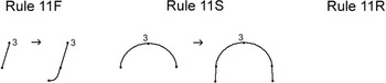
Labeled curves provide the most direct way to drive the automobile grammar. Because the automobile is composed of certain characteristics, labels are used to ensure that each of these characteristics is added. The labels themselves are not enough to constrain the rule applications. In this grammar, a combination of parametric shape recognition and labels are required for many of the rule applications. For example, in rule 9, if only label 3 exists, the top of the front wheel well can be added (Fig. 1). However, if label 3 exists and there is a related parametric curve, then rule 11 should be used (Fig. 2), which adds in the lower part of the front wheel well. Note that the letters following the rule numbers represent the view: F, S, and R are the front, side, and rear, respectively.

Rule 9 demonstrating the use of labels; F, front; S, side; R, rear.

Rule 11 demonstrating the use of labels in a parametric rule.
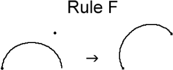
Labeled curves drive the insertion of the characteristics of the vehicle, but markers and shape recognition are used for the modification of these shapes. The shape modification rules can be applied to any curve that still has the nonlabeled end points. For example, in rule F (Fig. 3), a curve can be rotated about one of its end points. This rule can be applied to any curve that has two nonlabeled, or labeled, end points. There are additional constraints to this rule application, such as rule H must be applied first, which are discussed in further detail later.
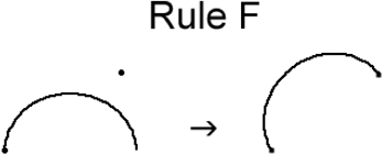
The example shape modification rule.
3. VEHICLE SAMPLE
As stated previously, vehicles were chosen from three known classes: coupes, pickups, and SUVs. The requirements were that each vehicle have a blueprint that included the front, side, and rear views; that each of the views be isometric (or as close as possible); and that the three views complement each other parametrically. Table 1 indicates the sample vehicles for each class.
Vehicle sample used to derive shape grammar

All vehicles chosen were the most recently available model year. All pickups chosen were extended cab models. This eliminated outliers in the set. It was also foreseen that crew cab models would be able to be drawn from the rules used to create SUVs. The coupes were all standard coupes. Any vehicles considered to be anomalies in their class were not chosen for the vocabulary.
Three vehicles, one from each class, were separated out as a control group. To confirm that the shape grammar was constructed properly, these vehicles that were not used to derive the vocabulary were built with the completed grammar (Table 1).
4. CHARACTERISTICS
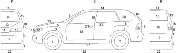
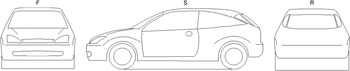
Because one of the intentions of this shape grammar was to define the vehicle classes, it was necessary to carefully consider which vehicle characteristics should be used. Through discussion with vehicle designers, it was determined that the following vehicle characteristics are the most relevant in the early stages of vehicle design (see Fig. 4): (1) front wheels, (2) rear wheels, (3) front wheel well, (4) rear wheel well, (5) front fender, (6) rear fender, (7) front bumper, (8) rear bumper, (9) front windshield, (10) rear windshield, (11) grill, (12) headlight, (13) hood, (14) roof, (15) trunk, (16) taillight, (17) rocker, (18) door, (19) front side window, (20) rear side window, (21) door handle, (22) ground, and (23) belt line.

The vehicle characteristics included in the shape grammar: (1) front wheels, (2) rear wheels, (3) front wheel well, (4) rear wheel well, (5) front fender, (6) rear fender, (7) front bumper, (8) rear bumper, (9) front windshield, (10) rear windshield, (11) grill, (12) headlight, (13) hood, (14) roof, (15) trunk, (16) taillight, (17) rocker, (18) door, (19) front side window, (20) rear side window, (21) door handle, (22) ground, and (23) belt line.
The belt line, which starts at the bottom of the A-pillar and runs along the bottom of the side windows to the trunk, is an important characteristic. There are no specific rules for the belt line, but it is built using a combination of the related characteristics: the hood, side windows, and trunk.
Each characteristic is defined by a curve or set of curves. These curves were captured manually through the following process:
- A vehicle's blueprint was imported as an image plane into Alias DesignStudio.
- Each characteristic was traced using Bezier curves (four control points), except wheels that use circles.
- The minimum number of curves was used to capture the characteristic accurately.
- This was done for each of the three views.
The curves defining the characteristics where then used as the vocabulary with which the shape grammar rules were written.
5. SHAPE GRAMMAR RULES
With the vocabulary extracted from the characteristics, 70 rules were written. The rules were written in such a way as to follow a logical progression in the creation of the vehicle, not to minimize the number of rules. This method of progression, although not exactly what an automotive designer would use, was confirmed to be appropriate by an automotive designer. Sixty-one of these rules are vehicle characteristic rules that are used to build the actual vehicle characteristics. These rules are driven by labels. Nine of these rules are general modification rules for curves. These 9 rules can be applied to any curve, in any view, that still has the appropriate marker at its end points. These rules are also constrained by the allowable parameters for the curves to which they are applying, which is described in further detail later in this paper. Each vehicle characteristic rule starts with a number followed by a letter that represent the view (F for front, S for side, R for rear). Thus, the views are connected by their rule number, and the application of a rule is carried through the different views. For example, if rule 1 positions the ground, then rule 1F will be the front instantiation of rule 1S. Linking rules together has been shown to be an effective way to implement a grammar with more than one component (Agarwal & Cagan, 1998; Knight, 2003).
There are constraints in each rule application:
- A grey shape or label on the left-hand side indicates that that curve or label must not exist for the rule to be applied. This constraint, although not standard, is necessary to prevent certain rules from being applied multiple times and still keep continuity of the design process.
- A grey label on the right-hand side indicates a removed label.
- Parametric ranges prevent certain instances, for example, the rocker cannot be lower than the ground.
- The general modification rules are applicable to any shape in any view, as long as it still has its end-point markers.
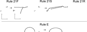
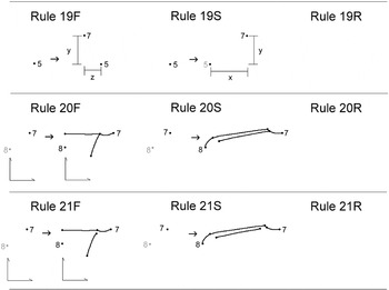
- Vertical modification of a shape in a view must match a vertical modification of a shape in its related view. For example, when rule 21 (Fig. 5) is applied label 8 must have the same vertical position in both the front and side views.
- If a curve is modified, the related curves must be modified accordingly. Connected end points are not allowed to disconnect, unless indicated by the rule. For example, if rule E (Fig. 5) is applied to the upper curve of a round headlight, the lower curve must also then be modified accordingly.

Example rules for understanding the grammar.
Because of the labels, the vehicle characteristic rules must follow in a general order, although for some characteristics the order can vary somewhat. However, once a characteristic is placed, the modification of that characteristic is only limited by the parametric constraints and the termination rule. This allows the designer a great degree of flexibility in modifying an initial design.
The rules were first built using just the forms from the coupe vehicle class. The pickup and SUV classes were then visited, which forced some rules to be added for some of the characteristics. This helped to define the differences between the vehicle classes. This set up a methodology for future extensions to other vehicle classes. Each rule in the shape grammar and its constraints is now explained in detail. There are 61 vehicle characteristic rules that place the actual vehicle forms. These can then be modified by the 9 general modification rules.
5.1. Vehicle characteristic rules
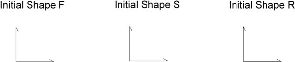
The initial shape (Fig. 6) is the relative coordinate system. The front and rear horizontal are linked and the vertical in all three views is linked.
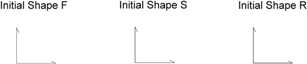
The initial shape.
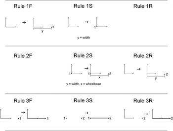
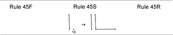
The ground rules (Fig. 7) are used to set the placement of the wheels. Rule 1 sets the wheel width, rule 2 sets the wheel base, and rule 3 inserts the ground below the vehicle.

The ground rules.
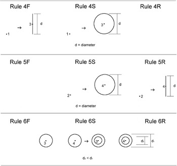
The wheel rules (Fig. 8) are used to build the front and rear wheels. Rule 4 inserts the front tire of a specified diameter. Rule 5 inserts the rear tire, which may or may not be the same diameter as the front tire. Rule 6 inserts the rim, which is a diameter that is less than the diameter of the tire.

The wheel rules.
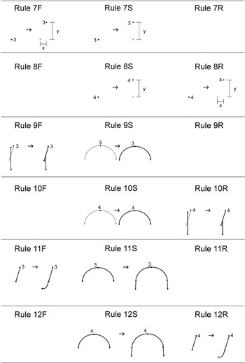
The wheel well rules (Fig. 9) insert the front and rear wheel wells. Rules 7 and 8 position the front and rear wheel wells, respectively, in relation to their wheels. Rules 9 and 10 insert the upper part of the wheel well. In these rules, as in all other rules that apply to more than one view, the vertical length of the curve must be the same in both views, that is, the bottom marker in rule 9 must have the same vertical coordinate in the front and side views. Rules 11 and 12 insert the lower part of the wheel well, which begins to define where the bumpers will be.

The wheel well rules.
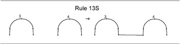
The rocker rule (Fig. 10) joins the front and rear wheel wells in the side view.

The rocker rule.
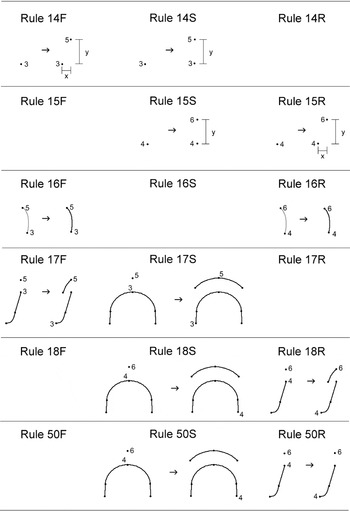
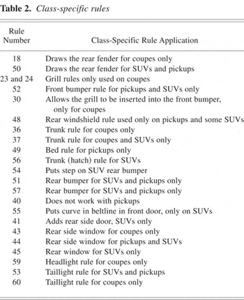
The fender rules (Fig. 11) insert the front and rear fenders. Rules 14 and 15 position the fender with respect to the wheel well, and rule 16 inserts the curve of the fender that is seen from only the front and rear views. Rules 17, 18, and 50 insert the fender. Rule 50 is used specifically for SUVs and pickups. Class-specific rules like this one will be addressed in more detail later in the article.

The fender rules.
The hood rules (Fig. 12) insert the hood. Rule 19 sets the intersection of the front windshield, hood, and A-pillar; it is positioned with respect to the front fender. Rule 20 inserts a hood in which the inner hood line is connected, and rule 21 inserts a hood in which the inner hood line is floating. Note that in both rules in the front view the hood must come all the way to the center of the vehicle as indicated by the spatial relationship with the initial shape.

The hood rules.
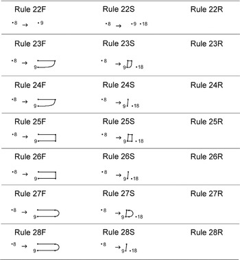
The grill rules (Fig. 13) insert the front grill. Rule 22 allows the front bumper to be attached directly to the hood. This is commonly used in coupes, in which it is followed by rule 30 (Fig. 14) that allows the grill to be inserted into the front bumper. Each grill rule inserts label 18, which holds the position for the headlight insertion rule. Rules 23–28 insert different types of grills. The odd numbered rules show the grill from the side view and the even numbered rules represent the grill as just a single curve in the side view. This is to delineate between grills that wrap around the front of the vehicle to the side and grills that are not visible from the side view.

The grill rules.

The front bumper rules.
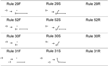
The front bumper rules (Fig. 14) insert the front bumper. Rules 29 and 52 insert upper front bumpers; the former has a connected horizontal line, and the latter has a disconnected horizontal line. When used sequentially, multiple front bumper forms can be inserted. Rule 30 is used in the instance that a grill is inserted into the front bumper, and rule 31 inserts the lower part of the front bumper and connects it to the front wheel well.
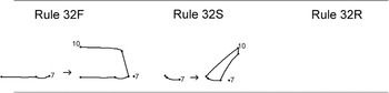
The front windshield rule (Fig. 15) inserts the front windshield and sets the position for the front side window with label 7. The form is basically the same for all vehicles but it can be modified using the shape modification rules detailed later.

The front windshield rule.
The roof rule (Fig. 16) inserts the roof. This rule is used on all vehicles, but the distance between labels 10 and 11 varies greatly.

The roof rule.
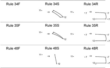
The rear windshield rules (Fig. 17) insert one of three different rear windshields.

The rear windshield rules.
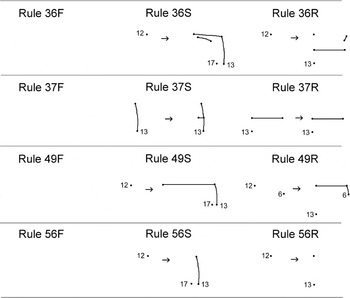
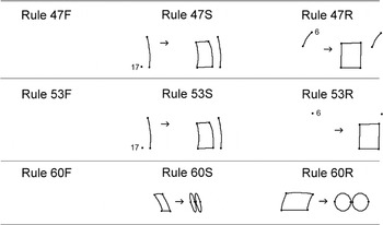
The trunk rules (Fig. 18) insert the section between the rear windshield and the rear bumper. In this set, label 17 sets where the tail light will be inserted. Rule 36 inserts a traditional trunk, and rule 49 inserts a pickup bed. Rule 56 inserts the bottom half of a hatch, which can be modified using rule 37.

The trunk rules.
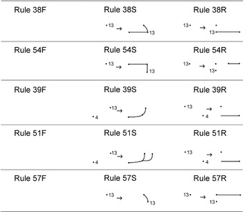
The rear bumper rules (Fig. 19) insert the rear bumpers. Rules 38 and 57 insert traditional upper rear bumpers. Rule 54 inserts a step in the rear bumper, commonly found on midsized SUVs. Rules 39 and 51 insert lower rear bumpers.

The rear bumper rules.
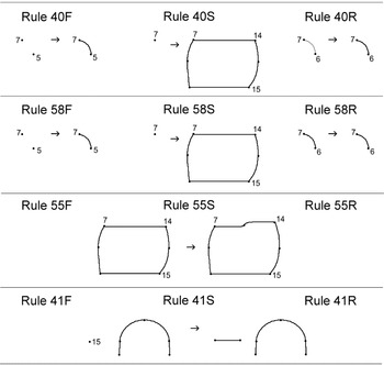
The door rules (Fig. 20) insert and modify side doors. Rules 40 and 58 insert the side door, with a variation in the rule depending on whether the side curve has already been drawn. The curve between labels 6 and 7 in the rear view is often inserted with the trunk. Rule 55 allows a change in the belt line, a curve found commonly on large SUVs and pickups. Rule 41 inserts a curve representing a rear side door.

The door rules.
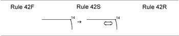
The door handle rule (Fig. 21) inserts a standard door handle that can then be modified.

The door handle rule.
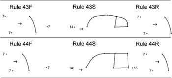
The front side window rules (Fig. 22) insert the side windows. Rule 43 is traditionally used with vehicles that do not have a rear side door, and rule 44 is used with vehicles that do have a rear side door. Rule 44 also sets label 16, which enables another side window to be inserted farther back.

The front side window rules.
The rear side window rule (Fig. 23) inserts a rear side window between the front side window and the rear windshield.

The rear side window rules.
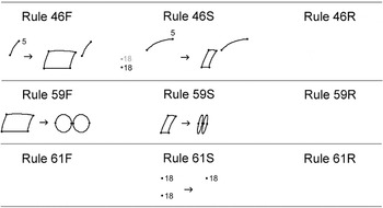
The headlight rules (Fig. 24) insert and modify the headlights. Rule 46 inserts a standard four-sided headlight that can be modified to curves using rule 59 or the general modification rules. If more than one label 18 was created when inserting the front bumper, rule 61 must be applied before the headlight can be inserted.

The headlight rules.
The taillight rules (Fig. 25) insert the taillights. Rule 47 is for coupes, and rule 53 is for pickups and SUVs. The difference again lies in the fact that certain curves are not visible from the rear view on pickups and SUVs. Rule 60 can be applied to change the four-sided taillight to two round taillights.

The taillight rules.
5.2. General modification rules
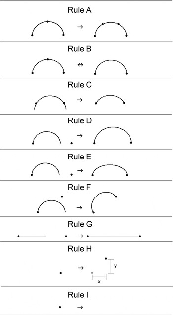
Figure 26 shows the general modification rules. These rules can be applied to any curve in any view, as long as the curve still has its end-point markers. There are constraints, in that a curve that exists in more than one view must necessarily have the same vertical dimension. The horizontal dimension in the front (or rear) and side views may not be the same. Rule A takes two curves and divides them into three similar curves. This is commonly used on fenders and wheel wells. Rule B changes two curves to one or vice versa. Rule C changes the arc through which a curve sweeps. Rule D scales a curve proportionally, and rule E scales a curve nonproportionally and is used quite frequently. Rule F rotates a curve about one end point. Rule G changes the length of a line. Rule H enables a labeled or nonlabeled point to be moved. This rule must first be applied to relocate one or more end points of a curve before rules C through G can be applied. This forces attached curves to remain attached at their end points throughout curve modifications. Rule H is also useful in the positioning of hoods, headlights, and taillights. Rule I is the terminal rule and removes all end points of the curves. Once this rule is applied throughout the vehicle, no more rules can be applied and the vehicle design is completed.

The general modification rules.
5.3. Rule application example
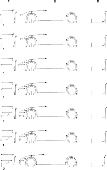
To better understand the application of these rules, and the purpose of the labels, the following example is given. This is a progression of the insertion of the grill and front fender, with modifications, for the Ferrari 612 Scaglietti. It is again noted that there is symmetry in the front and rear views, so that only half of the front and rear views will be produced and shown.
Figure 27a shows a finalized hood. Label 8 at the end of the hood allows for the start of the grill. Then, rule 22 is applied (Fig. 27b), to allow the front bumper to connect directly to the hood. This changes label 8 to label 9 and inserts label 18, which will eventually be used to insert the headlights. Rule 29 is applied (Fig. 27c), which builds the upper part of the front bumper. Rule 30 is applied (Fig. 27d), which adds a small part of the front bumper and inserts label 8, which allows the grill to be inserted into the front bumper. Rule 23 is used to insert the grill (Fig. 27e). Note that another label 18 is inserted. Now, the user must choose to eliminate one of the label 18s because the headlight insertion rule can only be applied with one label 18. The lower label 18 is removed using rule 61, and the grill curves are modified using rules H and E (Fig. 27f). Then, rule 31 is applied (Fig. 27g), which attaches the front bumper to the front wheel well. This also removes all labels associated with the front bumper and grill to eliminate the possibility of another set being added.

An example of rule progression.
6. DEFINING VEHICLE CLASSES BY CHARACTERISTICS
There are two different ways to define the vehicle classes. The first is to examine the derived rules. Certain rules are applicable to only certain classes. This enables the designer to limit the design to a certain class by choosing specific rules to keep the vehicle within that class. These class-specific rules are summarized in Table 2.
Class-specific rules

All other rules are universal and apply to every class of vehicle. It is important to note that the rules not in the list in Table 2 are applied to vehicle characteristics universally. These are characteristics that all classes of vehicles share, which may only be differentiated through parametric curve modification rules.
The second way to define vehicle classes is to examine differences between classes and define ranges of the parameters of the characteristics themselves. When a rule is universally applied, the differentiation of the characteristics is purely through the curve modification rules. Although all three classes share many of the same characteristics, which are applied using the same rules, the range in which the characteristics fall is limited within each vehicle class.
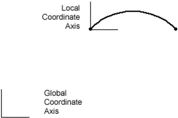
Each curve in the shape grammar is represented as a Bezier curve with four control points. The following examples include plots of the control points. Note that these are not plots of the curves themselves, but of their four control points. The curves are considered from two different coordinate systems, the global coordinate system and the local coordinate system (Fig. 28). The global coordinate system takes the point at which the front wheel touches the ground as its coordinate axis; the coordinate axis is seen in the side view of the initial shape (Fig. 6). This is consistent for all vehicles. The local coordinate system takes a common end point as the coordinate axis. The two different frames of reference enable us to discern differences between the parametric ranges from two different points of view.

Global versus local coordinate systems.
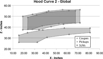
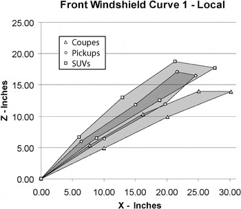
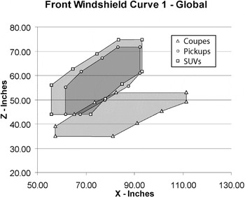
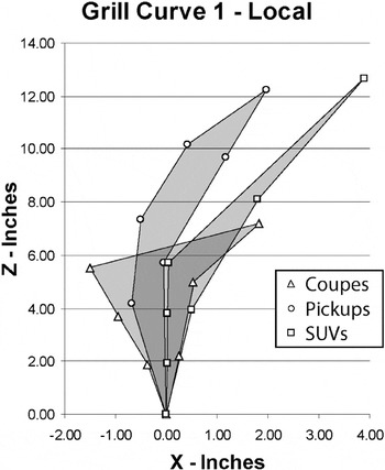
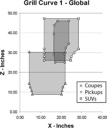
Figures 29, 30, 31, 32, 33, 34, 35, 36, 37, and 38 display detail for five curves to understand the parametric ranges that are allowed for universally applied rules: front fender, side, hood, front windshield, and grill. Control points for coupes, pickups, and SUVs are represented. Each figure shows the allowable range for the control points to stay within the designated vehicle class.

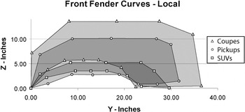
The front fender curve local coordinate system. The grey area surrounded by a symbol shows the allowable range for the control points to stay within the designated vehicle class.

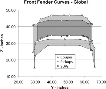
The front fender curve global coordinate system. The grey area surrounded by a symbol shows the allowable range for the control points to stay within the designated vehicle class.

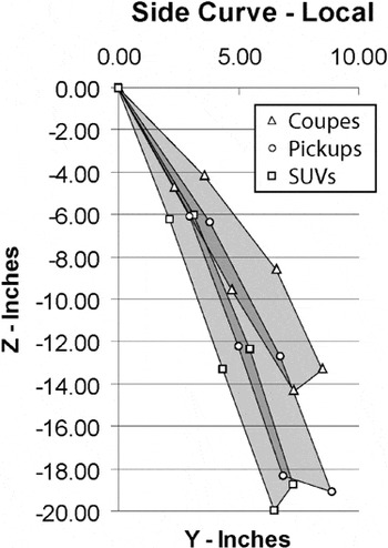
The side curve local coordinate system. The grey area surrounded by a symbol shows the allowable range for the control points to stay within the designated vehicle class.

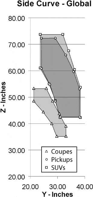
The side curve global coordinate system. The grey area surrounded by a symbol shows the allowable range for the control points to stay within the designated vehicle class.

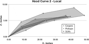
The hood curve local coordinate system. The grey area surrounded by a symbol shows the allowable range for the control points to stay within the designated vehicle class.

The hood curve global coordinate system. The grey area surrounded by a symbol shows the allowable range for the control points to stay within the designated vehicle class.

The front windshield local coordinate system. The grey area surrounded by a symbol shows the allowable range for the control points to stay within the designated vehicle class.

The front windshield curve global coordinate system. The grey area surrounded by a symbol shows the allowable range for the control points to stay within the designated vehicle class.

The grill curve local coordinate system. The grey area surrounded by a symbol shows the allowable range for the control points to stay within the designated vehicle class.

The grill curve global coordinate system. The grey area surrounded by a symbol shows the allowable range for the control points to stay within the designated vehicle class.
Figures 29 and 30 are graphs of the allowable ranges of the front fender, which is characteristic 5 in the side view of Figure 4. The front fender viewed from the side view is composed of two curves. In Figure 29 these two curves are joined to represent the front fender. Coupe fenders are taller and longer (i.e., a greater arc). Coupe fenders also have the largest range. SUV fenders are lower and flatter than coupe fenders, and they are vertically distinct from coupe fenders. Pickup fenders overlap the other two classes and almost entirely contain the SUV class.
In Figure 30 the coupe fenders are much lower than the SUV fenders and pickup fenders, which are almost identical. This shows that globally there is an accepted height for a coupe fender that is different for SUV and pickup fenders. It should be observed that the lower the pickup fender globally, the greater the arc locally; that is, the closer the fender gets to the ground, the more it resembles a coupe fender, and the higher it gets off the ground, the more it flattens out. This allows a differentiation to be made between small and large pickups.
Figures 31 and 32 refer to the side curve (characteristic 19) in the front and rear views of Figure 4. In Figure 31 the coupe sides have a much shallower ascent with a rounder curve and are generally shorter in height. Again, there is no overlap between coupe and SUV sides, which gives another differentiation between the classes. Pickup sides have the height of SUV sides, but they can have the curvature of coupe sides.
In Figure 32 the coupe sides have a much narrower and lower range than SUV or pickup sides. SUV and pickup sides line up almost exactly, although SUV sides are taller and higher. This also shows how wide a vehicle is at the point above the belt line. Coupes are narrower overall in comparison to SUVs and pickups. This enables a limitation in the width of a vehicle with this characteristic, with respect to its class. It is interesting to note, in general, that the higher and wider the vehicle is, the flatter the curvature of the side.
Figures 33 and 34 refer to the hood curve (characteristic 13) as seen in the side view of Figure 4. In Figure 33 the coupe hoods are much longer and can be taller than SUV and pickup hoods. Pickup and coupe hoods both have a greater curvature than SUV hoods, which are typically flatter. This shows that the range for SUV hoods is quite small and falls almost entirely within the coupe hood range. It is interesting to note that in general coupe hoods have a fairly consistent curvature whereas SUV hoods are sharp at the front and flatten out toward the windshield.
In Figure 34 the pickup and SUV hoods line up, and both are much higher than coupe hoods and initially farther back. Coupe hoods have the longest horizontal range and do not vary as much vertically. This sets a clear global differentiation between classes with respect to hoods. This can help in the development of new vehicles and can even be studied more closely to find further significance.
Figures 35 and 36 refer to the front windshield curve (characteristic 9) in the side view of Figure 4. In Figure 35 the SUV windshields are much steeper and have no overlap in their range with the shallower, longer coupe windshields. This shows a clear distinction between the traditionally allowable ranges for coupe and SUV windshields. Pickup windshields fall tightly within the SUV windshield range, but they have their lower end overlapping slightly with coupe windshields.
In Figure 36 the coupe windshields are much lower than SUV and pickup windshields, and the range varies mostly horizontally. SUV windshields have the largest vertical range, with a move back as height increases. Pickup windshields vary slightly vertically, but not much horizontally. Although the positioning and length varies throughout the ranges and classes, the curvature of the front windshields remains fairly consistent.
Figures 37 and 38 refer to the grill curve (characteristic 11) in Figure 4. In Figure 37 the coupe grills are much shorter in height than pickup and SUV grills. They can even be negative with respect to the local coordinate system, if located in the front fender. Pickup grills are as tall as SUV grills, but only as long as coupe grills. SUV grills have the greatest range, from short and upright to tall and long, but they stay entirely in the positive side. This shows where the limitations of the classes are with respect to the grill.
In Figure 38 the coupe grills are much lower than the other two and come farther forward, because of nose length and location within the bumper. SUV and pickup grills are similar in height range and horizontal average, but SUV grills have a broader horizontal range. Both come farther back than coupe grills, because of shorter noses. Again, a clear distinction is made between the classes. It should be noted that SUV and pickup grills tend to curve consistently, whereas coupe grills curve sharply at the beginning or the end. This is the inverse of what occurs in the hood (Fig. 33). This shows that where the form changes from vertical to horizontal in the front end is in the grill for coupes and in the hood for SUVs. This is important to consider in the creation of vehicles, so that the transition point is not duplicated (i.e., so there is no sharp curve in the grill and the hood).
These figures demonstrate that the global position of the curve and the local shape of the curve determine within which class the vehicle falls. This not only allows the vehicle classes to be clearly defined, but also allows for experimentation with cross-over vehicles. By following the trends exhibited in these figures, traditional vehicle classes will be maintained. By ignoring or modifying the parametric constraints or, for example, even being so bold as to invert them, simple changes in single characteristics can cause the vehicle being created to defy the boundaries of that vehicle class. For example, it was shown in Figure 32 that the taller and wider a side curve, the flatter it became. One could reverse this so that a tall and wide side curve was as rounded as the lower and shorter ones. The change of this one characteristic would begin to push the vehicle outside the traditional bounds of its class. This will be discussed in detail and shown later.
7. PROOF OF CONCEPT
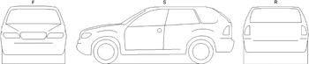
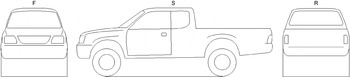
The first logical test of a shape grammar is to ensure that the vehicles that were used to derive the initial vocabulary can be recreated. One representative vehicle from each of the classes is recreated to confirm the shape grammar rules. In the following figures, the front and rear views of the completed drawings were mirrored about the middle to show the completed vehicle design. To represent the coupes, a Ferrari 612 Scaglietti was generated using 49 rule applications (Fig. 39). A GMC Canyon (Fig. 40) was generated in 45 rule applications for the pickups. Finally, the SUV chosen was a BMW X5 (Fig. 41), generated in 52 rule applications.

The Ferrari 612 Scaglietti coupe from the sample.

The GMC Canyon pickup from the sample.

The BMW X5 SUV from the sample.
The Ferrari and the GMC were both generated using the rules as sequentially as possible. The BMW was generated using the rules as nonsequentially as possible. It took more steps to build the vehicle; but it showed that even though the rules were applied in a different order, the result was still a completed vehicle.
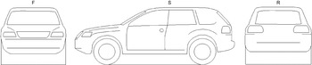
Three control vehicles, one from each class, were left out of the initial vocabulary: BMW 645, Mitsubishi L200, and Volkswagen Touareg. To test if the shape grammar properly represents the language of design for coupes, pickups, and SUVs, each of these vehicles was generated using this grammar. The completed designs are shown with the front and rear views mirrored in Figures 42, 43, and 44.

The BMW 645 coupe from the control group.

The Mitsubishi L200 pickup from the control group.

The Volkswagen Touareg SUV from the control group.
Next, to test the vocabulary of the shape grammar, an existing vehicle was designed that overlapped between the classes. A Ford Focus (Fig. 45) was chosen because it used rules from both the coupe and the SUV to build it. This vehicle was not part of the original sample, but we were able to draw it from the derived vehicle vocabulary using 50 rule applications.

The Ford Focus.
The front end of the Ford Focus was created using the same rules for coupes. However, once the windshield was done, the roof was created using the parametric range for SUVs. Then, the rear windshield and trunk were created from SUV rules. The real innovation here was with the taillights. By using rule H (translation of a point), label 17 could be moved to a unique position by the belt line. The taillight was then inserted and constrained by the geometry already in place. The details are given in the following paragraph.
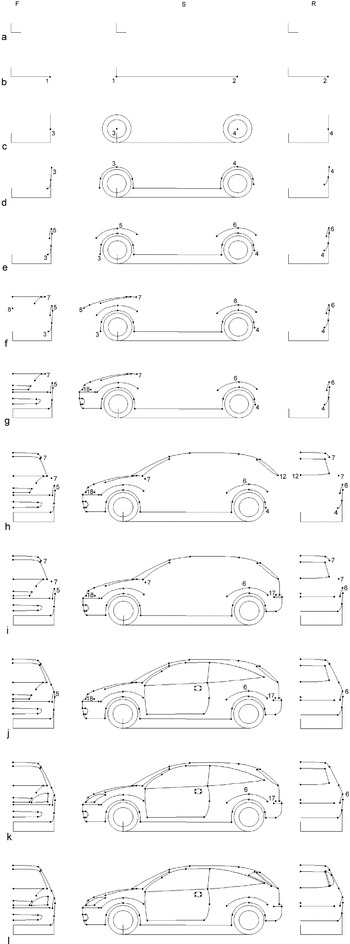
Figure 46 shows the complete generation of the Ford Focus. The process starts with the initial shape (Fig. 46a). Rules 1–3 are applied to insert the ground with the chosen wheel base and wheel width (Fig. 46b). Then rules 4–6 are applied to add the tires and the rims (Fig. 46c). Rules 7–10 add the upper part of the wheel wells, and rules E and H are applied to modify the shape of the upper wheel wells. Rules 11 and 12 add the lower wheel wells, followed by rules E and H to modify their shape. Rule 13 adds the rocker between the front and rear wheel wells (Fig. 46d). Rules 14–18 add the fenders and are followed by rules H, C, E, and F to modify their shapes (Fig. 46e). Rule 19 sets the base of the hood and rule 20 adds the hood (Fig. 46f). Rule 26 adds the grill, followed by rules H and G to modify the curve; rules 29 and 30 add the upper front bumper; rule 27 adds a lower grill, modified by rules H, E, and F; and rule 31 attaches the front bumper to the front wheel well (Fig. 46g). Rule 32 adds the windshield; rule 33 adds the roof; and rule 35 adds the rear windshield, which is then modified by rules H and F (Fig. 46h). Rule 56 adds the trunk, and rules 38 and 39 put in the rear bumper (Fig. 46i). Rule 58 inserts the door; rule I removes label 15 to prevent a rear door; rule 42 inserts the door handle, which is then modified by several applications of rules H and E; and rule 43 inserts the side windows, which are then modified using rules H and E (Fig. 46j). Rule 46 inserts the headlight, which is modified using rules H, B, and E (Fig. 46k). Rule H moves label 17 for the taillight; rule 47 inserts the taillight; and rules H, B, and E change the shape of the taillight (Fig. 46l). Rule I removes all the end points to give the finished vehicle shown in Figure 45, where the front and rear views are mirrored.

The Ford Focus build.
The intention of this shape grammar is to not only build existing vehicles, but also create new, unique vehicles. A vehicle was created that used the rules from all three classes and pushed the limits of the parametrics for the characteristics (Fig. 47). It also combined rules in ways to create new forms. It should be noted that this vehicle took only 52 rule applications to generate. Uniqueness is not entirely dependent upon the quantity of rule applications, but is dependent on how the rules are applied and within which class the particular characteristics fall.

The cross-over concept vehicle.
This vehicle also took the parameters for the side curve (Fig. 32) and reversed them. The side curve for this vehicle falls within the global parametric range for the coupe side curves. It then mixes the parameters for the curves by being as tall and wide as an SUV side curve, but still retaining the curvature that is indicative of a coupe side curve. Because of the way these parameters are combined, this side curve does not fall within any predefined category and is a true amalgamation of the two vehicle classes.
The first step to a unique form was to move directly from the hood to the grill. Multiple applications of bumper rules and then grill rules allowed for an interesting front end. The windshield followed the constraints for a coupe, but then an SUV style roof was inserted that ended in an SUV style rear window. Just to push the boundaries, a pickup bed was placed in the rear that ended in a coupe rear bumper. The front door had a wave put into the belt line, derived from Ford trucks. The coupe side windows were pushed to their limits. The addition of a rear side door, using an SUV rule, gave the appearance of a half-door like those found on Mazda RX-8s and Saturn's Ion Quad Coupe.
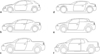
The grammar was then given to an automotive designer who produced the vehicles in Figure 48, showing only the side views. Figure 48a is an initial exploration on how the rules can be combined into unique forms. Figure 48b–d explore how, through simple parametric changes, a vehicle's form can be drastically altered and the class to which the vehicle belongs can be changed. Figure 48e and f are further explorations into the potential for new cross-over vehicle design using this grammar.

The automotive designer's concept vehicles using grammar.
To push the bounds of unique and interesting vehicles, one more was created (Fig. 49). The intention behind this design was to create a small urban delivery vehicle. The front end was as small as the parametric constraints allow, with a minimal amount of overhang. The greenhouse (the part of the automobile encompassed by the windows) was stretched to the parametric limits in order to facilitate the functionality of the vehicle, and the belt line was dropped to match the top of the fenders. Then, a small coupe rear window was inserted followed by a voluminous trunk for storage.

The unique concept vehicle.
8. CONCLUSIONS
Understanding the differences between vehicle classes is important for designing vehicles that meet the needs and desires of the consumer. The physical characteristics of a vehicle are consistent across all classes. How these characteristics are represented helps determine the differences between the vehicle classes. As was demonstrated, shape grammars are a tool that enable not only the understanding of these differences, but also the understanding of the implications of the design choices when designing vehicles. By having specific rules for each characteristic, the general form can be directed toward a specific class of vehicle. If such a characteristic is similar in all classes, then an understanding of the representative curves enables an understanding of the ranges that are acceptable for a certain class of vehicle.
By knowing which rules to apply and what form the characteristics can take, a class of vehicles can be explored for new and unique designs that may not have been thought of by the designer. By knowing the differences between the classes and combining rules and ranges, entirely new vehicles can be designed, which fall into none of the standard classes of vehicles. This unveils a new world for vehicle design that is not limited by traditional forms, but is instead open to designs that seek new forms and unique combinations of vehicle characteristics. As consumers continue to push toward multipurpose vehicles, these new forms will fill the design space where function and style from different vehicle classes merge.
Possible next steps are to include the top view in the grammar, which will facilitate a move toward developing curves and surfaces in 3-D. For a more robust vehicle class shape grammar, the other traditionally accepted vehicle classes can be added to the vocabulary: sports cars, sedans, vans, and station wagons. In addition, the creation of rules that enable asymmetry will open the potential for even more unique vehicle designs. Finally, the implementation of the vehicle class shape grammar in a shape grammar interpreter will begin to reveal the full potential of this work.
ACKNOWLEDGMENTS
The authors thank Ramesh Krishnamurti for his comments on the grammar. Funding for this research was provided by the National Science Foundation under Grant DMI-0245218 and by General Motors Corporation.