



1. Introduction
The initial lift immediately after the set-up of a wing/plate into steady motion suddenly or by acceleration is highly unsteady due to the formation of trailing edge and possibly leading edge vortices. The force production in wings impulsively started from rest was first studied by Wagner (Reference Wagner1925) for a flat plate at small angles of attack (AoA). Wagner assumed this vortex sheet to lie on the horizontal plane and solved the problem analytically. Though the initial circulation of the bound vortex is zero, Wagner found that the initial lift is half of its steady-state value, owing to the time variation of the circulation. The lift grows monotonically in time, following a curve now called the Wagner function, and reaches approximately 0.9 of its steady-state value after seven chord lengths of travel of the wing. These predictions, though based on the inviscid flow assumption, were verified experimentally by Walker (Reference Walker1931) using the RAF 130 airfoil at a Reynolds number of 140 000.
Wagner’s prediction is for the all-time behaviour of the unsteady lift, but has been found to be valid only for thin airfoils at very small AoA due to the assumption that the trailing edge vortex (TEV) sheet is planar (coplanar with the high-velocity surface at the trailing edge of the airfoil). The initial lift for a thick airfoil with a finite trailing edge angle was studied by Chow & Huang (Reference Chow and Huang1982). They still used the planar vortex sheet assumption to obtain a short-time approximation of the lift curve that gives a vanishing lift at the initial time for a finite trailing edge angle, in contrast to the Wagner solution, which gives a finite initial lift.
Later on, Graham (Reference Graham1983) pointed out that the planar sheet assumption is not adequate for short times. For short times, the TEV sheet rolls up to have a spiral shape (Pullin Reference Pullin1978), though it may be approximated by a concentrated (point) vortex (Graham Reference Graham1983). When the concentrated vortex at the trailing edge gets free to become a free vortex, or is seen to ‘detach’ from the trailing edge, a vortex sheet links the trailing edge and the TEV shed at the initial time. Graham (Reference Graham1983) used the concentrated vortex approximation to predict a short-time behaviour of the lift, which is initially singular and decreasing in time for impulsively started airfoils with trailing edge angles less than
 ${\rm\pi}/2$
. The lift drop lasts for a very short time period before the usually assumed monotonically increasing lift curve is reached.
For large enough AoA, a leading edge vortex (LEV), in the form of a vortex sheet spiral (Pullin & Wang Reference Pullin and Wang2004) or multiple concentrated vortices (Lu, Shen & Lai Reference Lu, Shen and Lai2006; Johansson et al. Reference Johansson, Engel, Kelber, Heerenbrink and Hedenstrom2013; Pitt Ford & Babinsky Reference Pitt Ford and Babinsky2013), may also be created.
The lift enhancing effect of the LEV has been extensively studied for three-dimensional problems, including flows over insect wings (Ellington et al. Reference Ellington, van den Berg, Willmott and Thomas1996; Bomphrey et al. Reference Bomphrey, Lawson, Harding, Taylor and Thomas2005; Muijres et al. Reference Muijres, Johansson, Barfield, Wolf, Spedding and Hedenstrom2008; Bomphrey, Taylor & Thomas Reference Bomphrey, Taylor and Thomas2009), artificially built flapping wings (Birch, Dickson & Dickinson Reference Birch, Dickson and Dickinson2004; Lu et al. Reference Lu, Shen and Lai2006; Johansson et al. Reference Johansson, Engel, Kelber, Heerenbrink and Hedenstrom2013; Pitt Ford & Babinsky Reference Pitt Ford and Babinsky2013), delta wings (Polhamus Reference Polhamus1966) and other flying objects (Lentink et al. Reference Lentink, Dickson, van Leeuwen and Dickinson2009; Muijres, Johansson & Hedenstrom Reference Muijres, Johansson and Hedenstrom2012). As pointed out by Xia & Mohseni (Reference Xia and Mohseni2013), early investigations for these problems to understand the basic physical flight mechanisms mainly used experimental studies to attribute the lift enhancing mechanism to the attached LEV. The LEV may be stably attached to the wing as a result of three-dimensional effects (Birch & Dickinson Reference Birch and Dickinson2001; Birch et al. Reference Birch, Dickson and Dickinson2004) or satisfaction of a self-equilibrium condition (Saffman & Sheffield Reference Saffman and Sheffield1977; Huang & Chow Reference Huang and Chow1982; Sakajo Reference Sakajo2012); thus a steady lift model based on attached LEV should yield useful results for these cases.
For large AoA starting flows with sharp leading edge, vortices are shed from both trailing and leading edges. The lift is highly unsteady and oscillatory according to experimental observations (Dickinson & Gotz Reference Dickinson and Gotz1993; Pitt Ford & Babinsky Reference Pitt Ford and Babinsky2013) and numerical computations (Xia & Mohseni Reference Xia and Mohseni2013). Hence, both the Wagner effect and the addtional vortex effect (such as that due to an LEV) impact the unsteady lift.
Dickinson & Gotz (Reference Dickinson and Gotz1993) summarized the insufficiency of earlier quasi-steady models without considering the Wagner effect for the lift of insect flight and pointed out that the Wagner lift curve alone is not appropriate for insect flight. Minotti (Reference Minotti2002) used conformal mapping to study the unsteady lift of a two-dimensional flapping wing with the Wagner effect discussed but then neglected. Pullin & Wang (Reference Pullin and Wang2004) studied an accelerating plate (with impulsive starting as a special case) at very high AoA with both LEVs and TEVs modelled as growing spiral sheets to obtain a lift formula for short times that predicts a lift quite different from that given by the original Wagner model. Michelin & Llewellyn Smith (Reference Michelin and Llewellyn Smith2009) studied the stability of coupled parallel plates where the vortical wake is represented as a vortex sheet. Pitt Ford & Babinsky (Reference Pitt Ford and Babinsky2013) measured the unsteady lift force for an accelerating plate and compared the measured bound circulation with that predicted by the Wagner model. They found that, for later times, the Wagner lift curve can be considered to be a first-order approximation of the circulatory part of the lift.
Though the Wagner effect is automatically taken into account in discrete vortex simulations (Yu, Tong & Ma Reference Yu, Tong and Ma2003; Ansari, Zbikowski & Knowles Reference Ansari, Zbikowski and Knowles2006a ,Reference Ansari, Zbikowski and Knowles b ; Ramesh et al. Reference Ramesh, Gopalarathnam, Edwards, OL and Granlund2011; Xia & Mohseni Reference Xia and Mohseni2013), by computational fluid dynamics (CFD) (Knowles et al. Reference Knowles, Wilkins, Ansari and Zbikowski2007) and by experimental measurements (Dickinson & Gotz Reference Dickinson and Gotz1993; Pitt Ford & Babinsky Reference Pitt Ford and Babinsky2013), it lacks a model that unifies the original Wagner theory and the force model that works for relatively large AoA. Moreover, the lift oscillating behaviour and the various lift peaks have not been well studied in the past.
The purpose of this study is therefore to obtain an unsteady lift model for all time, having the following properties:
-
(i) The model automatically switches to the original Wagner theory for small AoA and is accurate for relatively high AoA.
-
(ii) The model identifies the lift enhancing or lift decreasing role of a given vortex, predicts the oscillatory lift force behaviour, and identifies the origins of the various force peaks.
The lift model will be developed in § 2 for starting flows with relatively large AoA. Section 3 puts the lift formula into two convenient forms and builds a vortex force line (VFL) map for qualitative studies. Then the lift model is coupled with a discrete vortex simulation (appendix A) to obtain vortices with the results validated against numerical computation by CFD (see also appendix A), for an impulsively started flat plate at AoA up to
 $20^{\circ }$
. Section 4 summarizes the results.
2. Lift in the presence of a vortex sheet and additional vortices
In this section we assume an arbitrary number of vortices shed from the leading and trailing edges plus a quasi-planar vortex sheet (which may also be represented by discrete vortices), and derive an explicit lift expression in terms of modified Wagner functions and the properties of the additional vortices (other than the vortex sheet). This force expression will be rewritten in more convenient forms in § 3.
2.1. Vortex model and a primitive lift force formula
Consider a thin airfoil of chord length
 $c_{A}$
with a camber line defined by
 $y=f(x)$
for
 $0<x<c_{A}$
. The airfoil is abruptly set into motion, at an AoA of
 ${\it\alpha}$
, so in the body-fixed frame there is a uniform flow with velocity
 $V_{\infty }$
over the whole space at the initial time
 $t=0$
. For convenience, the vortex flow is decomposed into three stages (for one entire period if the lift or the flow is periodic or quasi-periodic in time).
-
(a) Initial stage
 $t<t_{0}$
(Graham lift drop stage). During this initial stage, vortices shed from both leading and trailing edges roll up to Kaden spirals. Analytical methods have been obtained by Graham (Reference Graham1983) (without LEV) and Pullin & Wang (Reference Pullin and Wang2004) (with both LEVs and TEVs) for small times.
-
(b) Middle stage
$t_{0}<t<t_{1}$
. The TEV spiral from the initial stage detaches from the trailing edge. Between this detached vortex spiral and the trailing edge, there is an extended piece of quasi-planar trailing vortex sheet. -
(c) Post stage
$t>t_{1}$
. Vortices shed at the trailing edge no longer follow the planar path as during
$t_{0}<t<t_{1}$
but appear as spirals or concentrated vortices.


As seen in figure 1, the vortex sheet developing during the middle stage is assumed to have intensity
 $k(s,t)$
(circulation) per unit length and to be spread over the interval
 $0<s<s_{0}=V_{\infty x}(t-t_{0})$
for
 $t>t_{0}$
. Here
 $s$
is defined as
 $s=x-c_{A}$
. For
 $t>t_{1}$
, the vortex sheet, if still considered to be planar, spreads over
 $s_{1}=V_{\infty x}(t-t_{1})<s<s_{0}=V_{\infty x}(t-t_{0})$
. Here
 $V_{\infty x}=V_{\infty }\cos {\it\alpha}\approx V_{\infty }+V_{\infty }O({\it\alpha}^{2})$
, but we may (and will) take
 $V_{\infty x}\approx V_{\infty }$
within the scope of the thin airfoil approximation used for this derivation. All the vortices, including the vortex spirals and the quasi-planar vortex sheet, may also be represented by a finite number of discrete vortices. For the present approach, the TEVs shed during the middle stage are either modelled as a quasi-planar vortex sheet (called method A or the modified Wagner approach) or represented by a number of discrete vortices (called method B or the no-vortex sheet approach). Other vortices (additional vortices) are always treated as discrete vortices. Method A reduces to the original Wagner model when additional vortices do not exist. Since method B is a special case of method A when the vortex sheet does not exist or is simply treated as a number of discrete vortices, method A only is derived.
Vortex system with a vortex sheet (VS) and an LEV and a TEV (which may both be composed of a number of discrete vortices). Along the airfoil there is a distributed bound vorticity (
 ${\it\gamma}$
) and along the VS the distributed vorticity is
 $k$
. This model is compared with figure 5 in § 3.3, where the vortices are obtained by discrete vortex simulation.

The non-dimensional time is defined by
 ${\it\tau}=V_{\infty }t/c_{A}$
(equivalent to the number of chord lengths travelled by the airfoil at constant speed in a ground-based frame of reference). With
 $t={\it\tau}c_{A}/V_{\infty }$
,
 ${\it\tau}_{0}=V_{\infty }t_{0}/c_{A}$
,
 ${\it\tau}_{1}=V_{\infty }t_{1}/c_{A}$
and
 $s=x-c_{A}$
, the relations for
 $s_{0}$
and
 $s_{1}$
can be written as
 $$\begin{eqnarray}\left\{\begin{array}{@{}lll@{}}\displaystyle s_{1}=0, & s_{0}=0, & \quad t<t_{0},\\ s_{1}=0, & s_{0}=c_{A}({\it\tau}-{\it\tau}_{0}), & \quad t_{0}<t<t_{1},\\ s_{1}=c_{A}({\it\tau}-{\it\tau}_{1}), & s_{0}=c_{A}({\it\tau}-{\it\tau}_{0}), & \quad t>t_{1}.\end{array}\right.\end{eqnarray}$$
To analyse all three stages in a general manner, we assume that, apart from the vortex sheet, there are
 $I=I(t)$
additional vortices of circulation
 ${\it\Gamma}_{v}^{(i)}$
at time-dependent positions
 $(x^{(i)},y^{(i)}),~i=1,2,\dots ,I$
. The velocity of each vortex is denoted as
 $$\begin{eqnarray}\boldsymbol{U}_{v}^{(i)}=\left(\frac{\text{d}x_{v}^{(i)}}{\text{d}t},\frac{\text{d}y_{v}^{(i)}}{\text{d}t}\right).\end{eqnarray}$$
The analysis uses the convention that the circulation of a vortex is positive if it is anticlockwise, for a right-going inflow. The properties of the additional vortices are assumed for qualitative analyses and will be given by discrete vortex simulations, CFD simulations or experimental measurements for quantitative analyses. Pitt Ford & Babinsky (Reference Pitt Ford and Babinsky2013) provided a method to identify vortices from experimental data of the velocity field. In this paper, additional vortices are obtained from the discrete vortex simulations and concentrated vortices are obtained from CFD computations (see § 3). The vortex sheet strength
 $k(s,t)$
is, however, determined theoretically under planar shape assumption.
Each vortex
 $(i)$
has non-dimensional coordinates (
 $p^{(i)},q^{(i)}$
) and non-dimensional circulation
 $\overline{{\it\Gamma}}_{v}^{(i)}$
, defined as
 $$\begin{eqnarray}p^{(i)}=\frac{x_{v}^{(i)}-\frac{1}{2}c_{A}}{\frac{1}{2}c_{A}},\quad q^{(i)}=\frac{y_{v}^{(i)}}{\frac{1}{2}c_{A}},\quad \overline{{\it\Gamma}}_{v}^{(i)}=\frac{{\it\Gamma}_{v}^{(i)}}{c_{A}V_{\infty }}.\end{eqnarray}$$
A distribution of vortices (called internal vortices) with intensity
 ${\it\gamma}(x)$
is assumed along the airfoil at any instant. The circulation of the usually defined bound vortex
 ${\it\Gamma}_{b}$
is
 ${\it\Gamma}_{b}=\int _{0}^{c_{A}}{\it\gamma}(x)\text{d}x$
. This vorticity distribution is determined by requiring satisfaction of the non-penetrating boundary condition along the wall and the Kutta condition at the trailing edge. The Kutta condition at the leading edge is satisfied through adding approximate LEVs in a proper way (appendix A).
For steady inviscid flow, the lift
 $L_{\infty }$
is given by the Kutta–Joukowski theorem,
 $L_{\infty }=-{\it\rho}V_{\infty }{\it\Gamma}_{\infty }$
. Here
 ${\it\Gamma}_{\infty }$
is the steady-state circulation of the bound vortex. A thin airfoil with a zero-lift AoA,
 ${\it\alpha}_{0}$
, has the following well-known expressions (Anderson Reference Anderson2010):
 $$\begin{eqnarray}L_{\infty }={\rm\pi}c_{A}{\it\rho}V_{\infty }^{2}{\it\alpha}_{e},\quad {\it\Gamma}_{\infty }=-{\rm\pi}c_{A}V_{\infty }{\it\alpha}_{e},\end{eqnarray}$$
where
 ${\it\alpha}_{e}={\it\alpha}-{\it\alpha}_{0}$
.
Various force theories can be used to derive the lift for a specific problem (Wu Reference Wu1981; Saffman Reference Saffman1992; Howe Reference Howe1995). For a rotational flow, the integral force formula by Wu (Reference Wu1981) can be used:
 $$\begin{eqnarray}L={\it\rho}\frac{\text{d}}{\text{d}t}\int _{D_{\infty }}{\it\omega}x\text{d}x\text{d}y+L_{r}.\end{eqnarray}$$
Here
 ${\it\omega}(x,y)$
is the vorticity, which satisfies the Kelvin theorem
 ${\it\Gamma}_{0}\equiv \int _{D_{\infty }}{\it\omega}\text{d}x\text{d}y=0$
at all times,
 $D_{\infty }$
is the entire space including the solid body (thus including images of the vortices), and
 $L_{r}$
is the non-circulatory lift due to the added mass effect. The added mass force term, for which the force formula is well known (Pullin & Wang Reference Pullin and Wang2004; Wu, Yang & Young Reference Wu, Yang and Young2012; Pitt Ford & Babinsky Reference Pitt Ford and Babinsky2013), can be treated separately and does not alter the other force components. Moreover, this analysis does not consider wing acceleration; thus
 $L_{r}$
is disregarded in this analysis. Equation (2.5) holds for both inviscid and viscous flows. For inviscid flows, a similar formula can be found in Saffman (Reference Saffman1992). For the present problem with additional vortices, vortex sheet in the fluid and distributed vortices along the airfoil, the total circulation in the entire space is
 ${\it\Gamma}_{o}={\it\Gamma}_{b}+\sum _{i=1}^{I}{\it\Gamma}_{v}^{(i)}+\int _{s_{1}}^{s_{0}}k(s,t)\text{d}s$
, so the Kelvin theorem gives
 $$\begin{eqnarray}{\it\Gamma}_{b}+\mathop{\sum }_{i=1}^{I}{\it\Gamma}_{v}^{(i)}+\int _{s_{1}}^{s_{0}}k(s,t)\text{d}s=0\quad \text{(Kelvin theorem)}.\end{eqnarray}$$
For regions outside of the vortex sheet and airfoil,
 ${\it\omega}=\sum _{i=1}^{I}{\it\delta}{\it\omega}_{v}^{(i)}$
, where
 ${\it\omega}_{v}^{(i)}$
is due to vortex
 $i$
only and
 ${\it\delta}={\it\delta}(x,y,x_{v}^{(i)},y_{v}^{(i)})$
is the Dirac delta function, with the vorticity due to a point vortex (Saffman Reference Saffman1992). Using the property of the Dirac delta function, it can be shown that
 $$\begin{eqnarray}\frac{\text{d}}{\text{d}t}\int _{D_{\infty }}{\it\delta}{\it\omega}_{v}^{(i)}x\text{d}x\text{d}y=\frac{\text{d}{\it\Gamma}_{v}^{(i)}x_{v}^{(i)}}{\text{d}t}.\end{eqnarray}$$
Decomposing the integral in (2.5) into three parts representing the contributions by the internal vortices
 ${\it\gamma}(x)$
along the airfoil, by the vortex sheet
 $k(s,t)$
and by the additional vortices
 ${\it\Gamma}_{v}^{(i)}$
, and using (2.6) and (2.7), gives the following more explicit force formula required for further studies:
 $$\begin{eqnarray}\left.\begin{array}{@{}c@{}}L=L_{b}+L_{v}+L_{s},\\ \displaystyle L_{b}=-{\it\rho}V_{\infty }{\it\Gamma}_{b}+{\it\rho}\frac{\text{d}{\it\Theta}}{\text{d}t},\quad {\it\Theta}_{b}(t)=\int _{0}^{c_{A}}{\it\gamma}x\text{d}x,\\ \displaystyle L_{v}={\it\rho}\mathop{\sum }_{D_{f}}\left(-V_{\infty }{\it\Gamma}_{v}^{(i)}+\frac{\text{d}{\it\Gamma}_{v}^{(i)}x_{v}^{(i)}}{\text{d}t}\right),\\ \displaystyle L_{s}=-{\it\rho}V_{\infty }\int _{s_{1}}^{s_{0}}k(s,t)\text{d}s+{\it\rho}\frac{\text{d}}{\text{d}t}\int _{s_{1}}^{s_{0}}k(s,t)(c_{A}+s)\text{d}s.\end{array}\right\}\end{eqnarray}$$
Here
 $L_{b}$
is due to the bound vortex,
 $L_{v}$
is due to the additional vortices and
 $L_{s}$
is due to the vortex sheet. Several remarks are required with regard to (2.8).
Remark 2.1. The lift is formally defined as the component of the force perpendicular to the inflow direction, not to the airfoil. For steady flow, the inviscid force is just the lift. According to Pullin & Wang (Reference Pullin and Wang2004), for a flat plate with vortex shedding from the leading edge (or when the Kutta condition is imposed at the leading edge), the direction of the inviscid force is, however, perpendicular to the flat plate. When the AoA is sufficiently small, this difference can be neglected. In this analysis, the coordinate system is chosen as shown in figure 1 and the lift is defined in the
 $y$
direction.
Remark 2.2. The lift component,
 $L_{b}$
, reduces to that given by the Kutta–Joukowski theorem when the flow is steady or when
 $\text{d}{\it\Theta}/\text{d}t=0$
. The force component,
 $L_{v}$
, due to additional vortices is known as the vortex force (Saffman Reference Saffman1992). For the problem considered in this paper, the flow is rotational, so the Blasius equation for irrotational flow,
 $$\begin{eqnarray}p+\frac{1}{2}(u^{2}+v^{2})=-\frac{\partial {\it\phi}}{\partial t}+C(t),\quad (u,v)\equiv \boldsymbol{{\rm\nabla}}{\it\phi},\end{eqnarray}$$
cannot be directly used to find the pressure
 $p$
and lift. Bai, Li & Wu (Reference Bai, Li and Wu2014) and Li, Bai & Wu (Reference Li, Bai and Wu2015) thus used a momentum approach to find the force formula without use of the Bernoulli equation. Equation (2.8) can also be derived using the approach of Li et al. (Reference Li, Bai and Wu2015), who used the original Wagner problem as a test problem. The approach by Li et al. (Reference Li, Bai and Wu2015) not only gives the force for a single airfoil flow, but also the individual force of each airfoil for multi-body flows with free vortices and vortex shedding.
Remark 2.3. The lift component,
 $L_{s}$
, takes the following general form if the vortex sheet is along a general curve
 $C(t)$
:
 $$\begin{eqnarray}L_{s}=-{\it\rho}V_{\infty }\int _{C(t)}k(c,t)\text{d}c+{\it\rho}\frac{\text{d}}{\text{d}t}\int _{C(t)}k(c,t)x\text{d}c,\end{eqnarray}$$
where
 $\text{d}c$
is an element on the curve
 $C(t)$
. When AoA is large enough and when the time is long enough, part of the TEV sheet will be at positions above that assumed by Wagner, due to self-induction. According to the VFL map presented in § 3.2, the force will be larger if the vortices are closer to the horizontal line from the trailing edge. Hence, forcing the vortex sheet to be along the direction as assumed by Wagner will overestimate the lift force for large time, as will become clear in § 3.
Remark 2.4. The force due to the vortex sheet must be treated with caution when this sheet is represented by a simple form suitable for mathematical manipulation. The vortex sheet must either be free or satisfy a zero-force condition or the Brown–Michael correction if it is represented as not free, since a free sheet cannot support a force (Brown & Michael Reference Brown and Michael1954; Graham Reference Graham1980). For instance, if a free vortex sheet in the form of a spiral is approximated by a non-free concentrated point vortex, a modified zero-lift force condition must be imposed (Graham Reference Graham1980, Reference Graham1983). This condition has also been used by Michelin & Llewellyn Smith (Reference Michelin and Llewellyn Smith2009) for falling cards where the wake is represented by point vortices. Here, for the present problem, the vortex sheet is considered to be a free sheet so that
 $\partial k/\partial t+u\,\partial k/\partial x=0$
, where
 $u$
is the local fluid velocity. Thus, as in the original Wagner problem (Saffman Reference Saffman1992),
 $(\text{d}/\text{d}t)\int _{s_{1}}^{s_{0}}sk(s,t)\text{d}s=\int _{s_{1}}^{s_{0}}u(s,t)k(s,t)\text{d}s$
, which reduces to
 $$\begin{eqnarray}\frac{\text{d}}{\text{d}t}\int _{s_{1}}^{s_{0}}sk(s,t)\text{d}s=V_{\infty }\int _{s_{1}}^{s_{0}}k(s,t)\text{d}s\end{eqnarray}$$
using the strong assumption that the vortex sheet convects at
 $V_{\infty }$
, as assumed in the original Wagner problem. If the last vortices being shed during a time interval are represented by one point vortex (say
 $i$
) as in discrete vortex simulations, the zero-lift force condition on these vortices means that (Graham Reference Graham1980)
 $$\begin{eqnarray}\frac{\text{d}x_{v}^{(i)}}{\text{d}t}+\frac{x_{v}^{(i)}-x_{TE}}{{\it\Gamma}_{v}^{(i)}}\frac{\text{d}{\it\Gamma}_{v}^{(i)}}{\text{d}t}=u.\end{eqnarray}$$
2.2. Circulation and moment of bound vorticity and vortex sheet
Equation (2.8) needs expressions for
 ${\it\Gamma}_{b}(t)=\int _{0}^{c_{A}}{\it\gamma}\text{d}x$
and
 ${\it\Theta}(t)=\int _{0}^{c_{A}}{\it\gamma}x\text{d}x$
. These are derived using a thin airfoil model in appendix B using the geometric parameters
 ${\it\lambda}_{n}^{(i)}$
,
 $C_{1}^{(i)}$
and
 $E_{1}^{(i)}$
(for each vortex
 $i$
) defined by
 $$\begin{eqnarray}\displaystyle & \displaystyle {\it\lambda}_{n}^{(i)}=\int _{0}^{{\rm\pi}}\frac{\cos (n{\it\beta})}{(p^{(i)}+\cos {\it\beta})^{2}+(q^{(i)})^{2}}\text{d}{\it\beta},\quad n\geqslant 0, & \displaystyle\end{eqnarray}$$
 $$\begin{eqnarray}\displaystyle & \displaystyle \left.\begin{array}{@{}c@{}}\displaystyle C_{1}^{(i)}=\frac{1}{{\rm\pi}}\left(p^{(i)}({\it\lambda}_{0}^{(i)}-{\it\lambda}_{1}^{(i)})+{\it\lambda}_{1}^{(i)}-\frac{{\it\lambda}_{0}^{(i)}+{\it\lambda}_{2}^{(i)}}{2}\right),\\ \displaystyle E_{1}^{(i)}=\frac{1}{4{\rm\pi}}\left((p^{(i)}-1)({\it\lambda}_{0}^{(i)}+{\it\lambda}_{2}^{(i)})+\left(\frac{3}{2}-2p^{(i)}\right){\it\lambda}_{1}^{(i)}+\frac{1}{2}{\it\lambda}_{3}^{(i)}\right).\end{array}\right\} & \displaystyle\end{eqnarray}$$
 ${\it\beta}$
is related to
 $x$
by
 $x={\textstyle \frac{1}{2}}c_{A}(1-\cos {\it\beta})$
. Appendix B shows that
 $$\begin{eqnarray}{\it\Gamma}_{b}={\it\Gamma}_{b}^{(0)}+{\it\Gamma}_{b}^{(v)}+{\it\Gamma}_{b}^{(s)},\quad {\it\Theta}_{b}={\it\Theta}_{b}^{(0)}+{\it\Theta}_{b}^{(v)}+{\it\Theta}_{b}^{(s)},\end{eqnarray}$$
where
 $$\begin{eqnarray}{\it\Gamma}_{b}^{(0)}={\it\Gamma}_{\infty },\quad {\it\Gamma}_{b}^{(v)}=\mathop{\sum }_{i=1}^{I}C_{1}^{(i)}{\it\Gamma}_{v}^{(i)},\quad {\it\Gamma}_{b}^{(s)}=\int _{s_{1}}^{s_{0}}\left(\frac{\sqrt{c_{A}+s}}{\sqrt{s}}-1\right)k(s,t)\text{d}s\end{eqnarray}$$
and
 $$\begin{eqnarray}\displaystyle & \displaystyle {\it\Theta}_{b}^{(0)}(t)=\frac{{\rm\pi}V_{\infty }c_{A}^{2}}{4}\left(-{\it\alpha}_{e}+\frac{2}{{\rm\pi}}c_{m,0}\right), & \displaystyle\end{eqnarray}$$
 $$\begin{eqnarray}\displaystyle & \displaystyle {\it\Theta}_{b}^{(v)}(t)=c_{A}\mathop{\sum }_{i=1}^{I}E_{1}^{(i)}{\it\Gamma}_{v}^{(i)}, & \displaystyle\end{eqnarray}$$
 $$\begin{eqnarray}\displaystyle & \displaystyle {\it\Theta}_{b}^{(s)}(t)=-\int _{s_{1}}^{s_{0}}\left(s+c_{A}-\sqrt{sc_{A}+s^{2}}\right)k(s,t)\text{d}s+\frac{c_{A}}{2}\int _{s_{1}}^{s_{0}}\frac{\sqrt{c_{A}+s}}{\sqrt{s}}k(s,t)\text{d}s. & \displaystyle\end{eqnarray}$$
 $c_{m,0}$
is the zero-lift moment for steady airfoil flow. The components
 ${\it\Gamma}_{b}^{(0)}$
and
 ${\it\Theta}_{b}^{(0)}$
are due to the geometry (AoA and camber) of the airfoil,
 ${\it\Gamma}_{b}^{(v)}$
and
 ${\it\Theta}_{b}^{(v)}$
are due to the additional vortices, and
 ${\it\Gamma}_{b}^{(s)}$
and
 ${\it\Theta}_{b}^{(s)}$
are due to the vortex sheet.
Summing the three relations in (2.16) yields
 $$\begin{eqnarray}\displaystyle {\it\Gamma}_{b}={\it\Gamma}_{b}^{(0)}+{\it\Gamma}_{b}^{(v)}-\int _{s_{1}}^{s_{0}}\left(1-\frac{\sqrt{c_{A}+s}}{\sqrt{s}}\right)k(s,t)\text{d}s. & & \displaystyle\end{eqnarray}$$
Substituting (2.18) into the Kelvin condition defined by (2.6) to eliminate
 ${\it\Gamma}_{b}$
gives the relationship for
 $k(s,t)$
as
 $$\begin{eqnarray}\int _{s_{1}}^{s_{0}}\frac{\sqrt{c_{A}+s}}{\sqrt{s}}k(s,t)\text{d}s=-{\it\Gamma}_{m},\end{eqnarray}$$
with
 ${\it\Gamma}_{m}={\it\Gamma}_{b}^{(0)}+{\it\Gamma}_{b}^{(v)}+\sum _{i=1}^{I}{\it\Gamma}_{v}^{(i)}$
(augmented bound circulation). If (2.16) is used,
 $$\begin{eqnarray}{\it\Gamma}_{m}={\it\Gamma}_{\infty }+\mathop{\sum }_{i=1}^{I}(1+C_{1}^{(i)}){\it\Gamma}_{v}^{(i)}.\end{eqnarray}$$
Now
 $k(s,t)$
is related to the solution
 $k^{(W)}(s,t)$
of the original Wagner problem, which satisfies
 $$\begin{eqnarray}\int _{0}^{V_{\infty }t}\frac{\sqrt{c_{A}+s}}{\sqrt{s}}k^{(W)}(s,t)\text{d}s=-{\it\Gamma}_{\infty }\end{eqnarray}$$
according to Saffman (Reference Saffman1992). Section C.1 gives some useful expressions from the original Wagner solution that are used in this paper. The expression for
 $k(s,t)$
is derived from the known function
 $k^{(W)}(s,t)$
using the similarity between (2.19) and (2.21). However, the ranges of the integrals in (2.19) and (2.21) differ. Thus, a correction
 ${\it\chi}({\it\tau},{\it\tau}_{0},{\it\tau}_{1})$
is defined to account for the difference:
 $$\begin{eqnarray}\int _{s_{1}}^{s_{0}}\frac{\sqrt{c_{A}+s}}{\sqrt{s}}k^{(W)}(s,t)\text{d}s=-{\it\chi}({\it\tau},{\it\tau}_{0},{\it\tau}_{1}){\it\Gamma}_{\infty }.\end{eqnarray}$$
The correction factor
 ${\it\chi}({\it\tau},{\it\tau}_{0},{\it\tau}_{1})$
is given an explicit expression in § C.1 (see (C 8)). Comparing (2.19) now with (2.22) gives
 $$\begin{eqnarray}k(s,t)=\frac{{\it\Gamma}_{m}}{{\it\chi}({\it\tau},{\it\tau}_{0},{\it\tau}_{1}){\it\Gamma}_{\infty }}\,k^{(W)}(s,t).\end{eqnarray}$$
2.3. Explicit lift formula
Splitting equation (2.15) for
 ${\it\Gamma}_{b}$
and
 ${\it\Theta}_{b}$
splits the bound vortex force into
 $L_{b}=L_{b}^{(0)}+L_{b}^{(v)}+L_{b}^{(s)}$
, where
 $$\begin{eqnarray}L_{b}^{(0)}=-{\it\rho}V_{\infty }{\it\Gamma}_{b}^{(0)}+{\it\rho}\frac{\text{d}{\it\Theta}_{b}^{(0)}}{\text{d}t},\quad L_{b}^{(v)}=-{\it\rho}V_{\infty }{\it\Gamma}_{b}^{(v)}+{\it\rho}\frac{\text{d}{\it\Theta}_{b}^{(v)}}{\text{d}t},\end{eqnarray}$$
 $$\begin{eqnarray}L_{b}^{(s)}=-{\it\rho}V_{\infty }{\it\Gamma}_{b}^{(s)}+{\it\rho}\frac{\text{d}{\it\Theta}_{b}^{(s)}}{\text{d}t}.\end{eqnarray}$$
The lift component
 $L_{b}^{(0)}$
is simply due to the geometry and AoA, component
 $L^{(v)}=L_{b}^{(v)}+L_{v}$
is the lift due to the additional vortices, and
 $L^{(s)}=L_{b}^{(s)}+L_{s}$
is the lift due to the vortex sheet. Both
 $L_{v}$
and
 $L_{s}$
are defined in (2.8). From (2.8) and (2.24), the total force can be more physically split as
 $$\begin{eqnarray}L=L^{(0)}+L^{(v)}+L^{(s)},\end{eqnarray}$$
where
 $$\begin{eqnarray}\left.\begin{array}{@{}c@{}}\displaystyle L^{(0)}=-{\it\rho}V_{\infty }{\it\Gamma}_{b}^{(0)}+{\it\rho}\frac{\text{d}{\it\Theta}_{b}^{(0)}}{\text{d}t},\\ \displaystyle L^{(v)}=-{\it\rho}V_{\infty }{\it\Gamma}_{b}^{(v)}+{\it\rho}\frac{\text{d}{\it\Theta}_{b}^{(v)}}{\text{d}t}+{\it\rho}\mathop{\sum }_{D_{f}}\left(-V_{\infty }{\it\Gamma}_{v}^{(i)}+\frac{\text{d}{\it\Gamma}_{v}^{(i)}x_{v}^{(i)}}{\text{d}t}\right),\\ \displaystyle L^{(s)}=-{\it\rho}V_{\infty }{\it\Gamma}_{b}^{(s)}+{\it\rho}\frac{\text{d}{\it\Theta}_{b}^{(s)}}{\text{d}t}-{\it\rho}V_{\infty }\int _{s_{1}}^{s_{0}}k(s,t)\text{d}s+{\it\rho}\frac{\text{d}}{\text{d}t}\int _{s_{1}}^{s_{0}}k(s,t)(c_{A}+s)\text{d}s.\end{array}\right\}\end{eqnarray}$$
First consider
 $L^{(0)}$
and
 $L^{(v)}$
. From (2.17a
) and (2.17b
),
 $\text{d}{\it\Theta}_{b}^{(0)}/\text{d}t=0$
and
 $\text{d}{\it\Theta}_{b}^{(v)}/\text{d}t=c_{A}\sum _{i=1}^{I}(\text{d}E_{1}^{(i)}{\it\Gamma}_{v}^{(i)})/\text{d}t$
. Using these and (2.16a,b
) gives
 $$\begin{eqnarray}\displaystyle & L^{(0)}=L_{\infty }=-{\it\rho}V_{\infty }{\it\Gamma}_{b}^{(0)}={\rm\pi}{\it\rho}c_{A}V_{\infty }^{2}{\it\alpha}_{e}, & \displaystyle\end{eqnarray}$$
 $$\begin{eqnarray}\displaystyle & \displaystyle L^{(v)}=-{\it\rho}V_{\infty }\mathop{\sum }_{D_{f}}(1+C_{1}^{(i)}){\it\Gamma}_{v}^{(i)}+{\it\rho}\mathop{\sum }_{i=1}^{I}\left(\frac{\text{d}{\it\Gamma}_{v}^{(i)}x_{v}^{(i)}}{\text{d}t}+c_{A}\frac{\text{d}E_{1}^{(i)}{\it\Gamma}_{v}^{(i)}}{\text{d}t}\right). & \displaystyle\end{eqnarray}$$
 $L^{(s)}$
is rather complex and the details are given in § C.2. The final expression for
 $L^{(s)}$
is
 $$\begin{eqnarray}L^{(s)}=-{\it\rho}V_{\infty }({\it\phi}({\it\tau},{\it\tau}_{0},{\it\tau}_{1})-1){\it\Gamma}_{m}-\frac{1}{2}{\it\rho}c_{A}({\it\psi}({\it\tau},{\it\tau}_{0},{\it\tau}_{1})+1)\frac{\text{d}{\it\Gamma}_{m}}{\text{d}t},\end{eqnarray}$$
where
 ${\it\phi}({\it\tau},{\it\tau}_{0},{\it\tau}_{1})$
and
 ${\it\psi}({\it\tau},{\it\tau}_{0},{\it\tau}_{1})$
are the modified Wagner functions defined in § C.3.
Using (2.20) for
 ${\it\Gamma}_{m}$
gives
 $$\begin{eqnarray}\frac{\text{d}{\it\Gamma}_{m}}{\text{d}t}=\mathop{\sum }_{i=1}^{I}\frac{\text{d}C_{1}^{(i)}}{\text{d}t}{\it\Gamma}_{v}^{(i)}=\frac{2}{c_{A}}\mathop{\sum }_{i=1}^{I}\left(\frac{\partial C_{1}^{(i)}}{\partial p^{(i)}}\frac{\text{d}x^{(i)}}{\text{d}t}+\frac{\partial C_{1}^{(i)}}{\partial q^{(i)}}\frac{\text{d}y^{(i)}}{\text{d}t}\right){\it\Gamma}_{v}^{(i)}.\end{eqnarray}$$
Here
 $C_{1}^{(i)}$
and
 $E_{1}^{(i)}$
are defined by (2.14). Putting (2.27)–(2.29) into (2.25) gives
 $$\begin{eqnarray}L=-{\it\rho}V_{\infty }{\it\phi}({\it\tau},{\it\tau}_{0},{\it\tau}_{1}){\it\Gamma}_{m}-\frac{1}{2}{\it\rho}c_{A}({\it\psi}({\it\tau},{\it\tau}_{0},{\it\tau}_{1})+1)\frac{\text{d}{\it\Gamma}_{m}}{\text{d}t}+L_{m}^{(v)},\end{eqnarray}$$
where
 $L_{m}^{(v)}={\it\rho}\sum _{i=1}^{I}[(\text{d}{\it\Gamma}_{v}^{(i)}x_{v}^{(i)})/\text{d}t+c_{A}(\text{d}E_{1}^{(i)}{\it\Gamma}_{v}^{(i)})/\text{d}t]$
. Any additional free vortex has
 $\text{d}{\it\Gamma}_{v}^{(i)}/\text{d}t=0$
due to Kelvin’s theorem, hence
 $$\begin{eqnarray}\displaystyle & \displaystyle L_{m}^{(v)}={\it\rho}\mathop{\sum }_{i=1}^{I}\left(H^{(i)}\frac{\text{d}x^{(i)}}{\text{d}t}+V^{(i)}\frac{\text{d}y^{(i)}}{\text{d}t}\right){\it\Gamma}_{v}^{(i)}+L_{p}^{(LE)}+L_{p}^{(TE)}, & \displaystyle\end{eqnarray}$$
 $$\begin{eqnarray}\displaystyle & \displaystyle H^{(i)}=1+2\frac{\partial E_{1}^{(i)}}{\partial p^{(i)}},\quad V^{(i)}=2\frac{\partial E_{1}^{(i)}}{\partial q^{_{(i)}}}. & \displaystyle\end{eqnarray}$$
The force components
 $L_{p}^{(LE)}$
and
 $L_{p}^{(TE)}$
, defined as
 $$\begin{eqnarray}\displaystyle L_{p}^{(LE)}={\it\rho}(x_{LE}+c_{A}E_{1}^{(LE)})\frac{\text{d}{\it\Gamma}_{LE}}{\text{d}t},\quad L_{p}^{(TE)}={\it\rho}(x_{TE}+c_{A}E_{1}^{(TE)})\frac{\text{d}{\it\Gamma}_{TE}}{\text{d}t}, & & \displaystyle\end{eqnarray}$$
are due to the production of vortices (or vortices being shed) at the leading and trailing edges, if this production force is not automatically taken into account in the other components of the lift.
-
(i) The second expression in (2.14) yields
$E_{1}^{(LE)}=0$
. Since
$x_{LE}=0$
,
$L_{p}^{(v)}=0$
. For the trailing edge,
$x_{TE}+c_{A}E_{1}^{(TE)}\neq 0$
. For small
$t$
, Graham (Reference Graham1983) gave an analytical expression for
${\it\Gamma}_{TE}$
, which in the case of a flat plate reduces to (2.35)The total lift, including the vortex production force, is
$$\begin{eqnarray}{\it\Gamma}_{TE}=2{\rm\pi}\left(\frac{4V_{\infty }}{c_{A}}\sin {\it\alpha}\right)^{4/3}\left(\frac{c_{A}}{4}\right)^{2}t^{1/3}\quad \text{(Graham circulation)}.\end{eqnarray}$$
$L\sim t^{-1/3}$
for
$t\rightarrow 0$
. This is known as the initial singularity of the lift.
-
(ii) In this analysis the vortices being shed from the trailing edge are either included in the vortex sheet or treated as newly shed discrete vortices. For the first case, this vortex production force is included in
$L_{s}$
. For the second case, a zero-lift force condition similar to (2.12) would mean
$L_{p}^{(LE)}=~L_{p}^{(TE)}=0$
. For these reasons, both
$L_{p}^{(LE)}$
and
$~L_{p}^{(TE)}$
will not be included in the discrete vortex simulations (§ 3) with the correctness of this assumption verified by CFD simulations. See Xia & Mohseni (Reference Xia and Mohseni2013) for more discussion of this subject in discrete vortex simulations and for analytical treatment of the vortex force production.











3. Analysis of the lift for a flat plate
In this section the lift formula is rewritten in two alternative forms convenient for physical analyses. A VFL map is generated to identify the lift enhancing or lift decreasing role of a given vortex. The specific roles of the LEVs and TEVs and the time evolution of the lift for an impulsively starting flat plate (
 ${\it\alpha}_{0}=c_{m,0}=0$
) will be studied in detail.
3.1. Method A: modified Wagner approach or additional vortex force approach
In this approach, the TEVs shed during
 $t_{0}<t<t_{1}$
are treated as a continuous quasi-planar vortex sheet and the other vortices are treated as discrete vortices, called additional vortices. The lift formula is rewritten in a form where the lift is seen as a correction to a Wagner-type lift, referred to as ‘additional’ in this paper. This approach may not work correctly for very large AoA and long times, since the vortex sheet would not follow a straight free streamline (and for the reason stated in Remark 2.3).
3.1.1. Lift formula
Inserting (2.20), (2.30) and (2.32) into (2.31) gives
 $$\begin{eqnarray}\displaystyle L & = & \displaystyle {\it\phi}({\it\tau},{\it\tau}_{0},{\it\tau}_{1})L_{\infty }+{\it\rho}\mathop{\sum }_{i=1}^{I}(O_{A}V_{\infty }+{\it\bf\Lambda}_{A}\boldsymbol{\cdot }\boldsymbol{U}_{v}^{(i)}){\it\Gamma}_{v}^{(i)}\nonumber\\ \displaystyle & = & \displaystyle {\it\phi}({\it\tau},{\it\tau}_{0},{\it\tau}_{1})L_{\infty }+{\it\rho}\mathop{\sum }_{i=1}^{I}(O_{A}V_{\infty }+{\it\bf\Lambda}_{A}\boldsymbol{\cdot }\boldsymbol{U}_{v}^{(i)}\cos {\it\theta}_{v}^{(i)}){\it\Gamma}_{v}^{(i)},\end{eqnarray}$$
where
 $\boldsymbol{U}_{v}^{(i)}$
is the velocity vector for vortex
 $i$
,
 ${\it\bf\Lambda}_{A}=(P_{A},Q_{A})$
is the additional VFL vector,
 ${\it\theta}_{v}^{(i)}$
(called the force line angle) is the angle between the vector
 $\boldsymbol{U}_{v}^{(i)}$
(problem-dependent) and the vector
 ${\it\bf\Lambda}_{A}$
(problem-independent), and
 $O_{A}$
,
 $P_{A}$
and
 $Q_{A}$
are additional vortex force factors defined by
 $$\begin{eqnarray}\left.\begin{array}{@{}c@{}}O_{A}=-{\it\phi}({\it\tau},{\it\tau}_{0},{\it\tau}_{1})(1+C_{1}),\\ \displaystyle P_{A}=1-({\it\psi}({\it\tau},{\it\tau}_{0},{\it\tau}_{1})+1)\frac{\partial C_{1}}{\partial p}+2\frac{\partial E_{1}}{\partial p},\\ \displaystyle Q_{A}=-({\it\psi}({\it\tau},{\it\tau}_{0},{\it\tau}_{1})+1)\frac{\partial C_{1}}{\partial q}+2\frac{\partial E_{1}}{\partial q}.\end{array}\right\}\end{eqnarray}$$
Here
 $p,~q,~{\it\lambda}_{n},~C_{1}$
and
 $E_{1}$
are defined by
 $$\begin{eqnarray}\left.\begin{array}{@{}c@{}}\displaystyle p=\frac{x_{v}^{(i)}-\frac{1}{2}c_{A}}{\frac{1}{2}c_{A}},\quad q=\frac{y_{v}^{(i)}}{\frac{1}{2}c_{A}},\quad {\it\tau}=\frac{V_{\infty }t}{c_{A}},\\ \displaystyle {\it\lambda}_{n}=\int _{0}^{{\rm\pi}}\frac{\cos (n{\it\beta})}{(p+\cos {\it\beta})^{2}+(q)^{2}}\text{d}{\it\beta},\quad n\geqslant 0,\\ \displaystyle C_{1}=\frac{1}{{\rm\pi}}\left(p({\it\lambda}_{0}-{\it\lambda}_{1})+{\it\lambda}_{1}-\frac{{\it\lambda}_{0}+{\it\lambda}_{2}}{2}\right),\\ \displaystyle E_{1}=\frac{1}{4{\rm\pi}}\left((p-1)({\it\lambda}_{0}+{\it\lambda}_{2})+\left(\frac{3}{2}-2p\right){\it\lambda}_{1}+\frac{1}{2}{\it\lambda}_{3}\right),\end{array}\right\}\end{eqnarray}$$
and
 ${\it\phi}$
and
 ${\it\psi}$
are modified Wagner functions. According to § C.3, these modified Wagner functions are
 $$\begin{eqnarray}\left.\begin{array}{@{}c@{}}\displaystyle {\it\phi}({\it\tau},{\it\tau}_{0},{\it\tau}_{1})=\frac{1}{{\it\chi}({\it\tau},{\it\tau}_{0},{\it\tau}_{1})}(F^{(W)}({\it\tau}_{1})-F^{(W)}({\it\tau}_{0}))+\frac{1}{2}\frac{\text{d}}{\text{d}{\it\tau}}{\it\psi}({\it\tau},{\it\tau}_{0},{\it\tau}_{1}),\\ \displaystyle {\it\psi}({\it\tau},{\it\tau}_{0},{\it\tau}_{1})=\frac{2}{{\it\chi}({\it\tau},{\it\tau}_{0},{\it\tau}_{1})}\int _{{\it\tau}_{0}}^{{\it\tau}_{1}}\left(\sqrt{({\it\tau}-m)+({\it\tau}-m)^{2}}-({\it\tau}-m)\right)G^{(W)}(m)\text{d}m,\\ \displaystyle {\it\chi}({\it\tau},{\it\tau}_{0},{\it\tau}_{1})=\int _{{\it\tau}_{0}}^{{\it\tau}_{1}}\frac{\sqrt{1+{\it\tau}-m}}{\sqrt{{\it\tau}-m}}\,G^{(W)}(m)\text{d}m,\end{array}\!\!\!\right\}\end{eqnarray}$$
where, according to § C.1,
 $F^{(W)}({\it\tau})$
and
 $G^{(W)}({\it\tau})$
can be approximated as
 $$\begin{eqnarray}\left.\begin{array}{@{}c@{}}\displaystyle F^{(W)}({\it\tau})\approx 1-0.8123\text{e}^{-\sqrt{{\it\tau}}/1.276}-0.188\text{e}^{-{\it\tau}/1.211}+0.32683\times 10^{-3}\text{e}^{-{\it\tau}^{2}/0.892},\\ \displaystyle G^{(W)}({\it\tau})\approx \frac{8.0}{\sqrt{{\it\tau}}}\left(0.0398\text{e}^{-0.784\sqrt{{\it\tau}}}+0.0194\sqrt{{\it\tau}}\text{e}^{-0.826{\it\tau}}-9.16\times 10^{-5}{\it\tau}^{3/2}\text{e}^{-1.121{\it\tau}^{2}}\right).\end{array}\right\}\end{eqnarray}$$
3.1.2. Validation of the lift formula
As a particular case of the stationary vortex problem of Saffman & Sheffield (Reference Saffman and Sheffield1977), Saffman (Reference Saffman1992, p. 122) considered a vortex of strength
 $$\begin{eqnarray}{\it\Gamma}_{v}=-{\rm\pi}V_{\infty }\frac{(h^{\prime 2}-a^{2})^{2}(h^{\prime 2}+a^{2})}{2a^{2}h^{\prime 3}}\,\frac{h^{\prime 2}+a^{2}}{h^{\prime 2}-a^{2}}=-{\rm\pi}V_{\infty }\frac{(h^{\prime 2}-a^{2})(h^{\prime 2}+a^{2})^{2}}{2a^{2}h^{\prime 3}}\end{eqnarray}$$
at a distance
 $h$
above the middle of a flat plate with
 ${\it\alpha}=0$
. Here
 $h^{\prime }=h+\sqrt{a^{2}+h^{2}}$
and
 $a=c_{A}/2$
. For this particular case,
 ${\it\tau}\rightarrow \infty$
,
 $L_{\infty }=0$
,
 $I=1$
,
 $\text{d}x_{v}^{(1)}/\text{d}t=\text{d}y_{v}^{(1)}/\text{d}t=0$
,
 $p=0$
and
 $q=2h/c_{A}$
, and (3.1) reduces to
 $$\begin{eqnarray}L_{present}=-(1+C_{1}){\it\rho}V_{\infty }{\it\Gamma}_{v}.\end{eqnarray}$$
Such a vortex is stationary, that is, the flow velocity due to the interaction between the plate and the vortex, with
 ${\it\Gamma}_{v}$
given by (3.6), vanishes at the position of this vortex. Using conformal mapping Saffman obtained the following lift formula for the flat plate:
 $$\begin{eqnarray}L_{Saffman}=-{\rm\pi}{\it\rho}V_{\infty }^{2}\frac{(h^{\prime 2}-a^{2})^{2}(h^{\prime 2}+a^{2})}{2a^{2}h^{\prime 3}}.\end{eqnarray}$$
To show whether (3.7) and (3.8) are the same, the expression for
 $C_{1}$
defined in (3.3) is rewritten as
 $$\begin{eqnarray}C_{1}=\frac{1}{{\rm\pi}}\int _{0}^{{\rm\pi}}\frac{\cos ({\it\beta})-\cos ^{2}{\it\beta}}{\cos ^{2}{\it\beta}+q^{2}}\text{d}{\it\beta}=\frac{\left(q+\sqrt{1+q^{2}}\right)^{2}-1}{\left(q+\sqrt{1+q^{2}}\right)^{2}+1}-1=\frac{h^{\prime 2}-a^{2}}{h^{\prime 2}+a^{2}}-1.\end{eqnarray}$$
Inserting this equation for
 $C_{1}$
and (3.6) for
 ${\it\Gamma}_{v}$
into (3.7) gives
 $$\begin{eqnarray}L_{present}=-{\rm\pi}{\it\rho}V_{\infty }^{2}\frac{h^{\prime 2}-a^{2}}{h^{\prime 2}+a^{2}}\frac{(h^{\prime 2}-a^{2})(h^{\prime 2}+a^{2})^{2}}{2a^{2}h^{\prime 3}}=-{\rm\pi}{\it\rho}V_{\infty }^{2}\frac{(h^{\prime 2}-a^{2})^{2}(h^{\prime 2}+a^{2})}{2a^{2}h^{\prime 3}},\end{eqnarray}$$
which is exactly the same as the Saffman result in (3.8).
3.1.3. Additional vortex force and additional vortex force map
The first term on the right side of (3.1) is a Wagner-type lift, which is the original Wagner lift when
 ${\it\tau}_{0}=0$
and
 ${\it\tau}_{1}={\it\tau}$
. Appendix C shows that the modified Wagner force
 ${\it\phi}({\it\tau},{\it\tau}_{0},{\it\tau}_{1})L_{\infty }$
is slightly smaller than the original Wagner force
 ${\it\Phi}({\it\tau})L_{\infty }$
if
 ${\it\tau}_{0}>0$
and
 ${\it\tau}_{1}={\it\tau}$
. The second term is due to the additional vortices and is called the additional vortex force term here. Hence, the lift force can be regarded as the sum of a Wagner-type lift plus an additional vortex force term. This additional vortex force term, which is apparently due to the influence of the additional vortices alone, is in fact coupled with the vortex sheet since the vortex factors are also functions of the modified Wagner function,
 ${\it\phi}$
(and even a new function
 ${\it\phi}$
related to the Wagner function). The additional vortex force factors
 $O_{A}$
,
 $P_{A}$
and
 $Q_{A}$
are explicit functions of the non-dimensional time
 ${\it\tau}$
and the non-dimensional coordinates
 $p,q$
(vortex position) and thus can be precomputed.
From (3.1), the correction from an additional vortex
 $i$
to the Wagner-type lift is composed of a stationary part
 $L_{st}={\it\rho}V_{\infty }O_{A}{\it\Gamma}_{v}^{(i)}$
and a non-stationary part
 $L_{nst}={\it\rho}{\it\bf\Lambda}_{A}\boldsymbol{\cdot }\boldsymbol{U}_{v}^{(i)}\cos {\it\theta}_{v}^{(i)}\,{\it\Gamma}_{v}^{(i)}$
. Hence, the force correction due to any additional vortex depends on the vortex force factors.
The force factor
 $O_{A}$
is shown in figure 2 and the additional VFL vector
 ${\it\bf\Lambda}_{A}$
is shown in figure 3, for
 ${\it\tau}_{0}=0$
and
 ${\it\tau}_{1}={\it\tau}$
for three typical instants
 ${\it\tau}=0$
, 1 and
 $\infty$
, in two-dimensional maps. The maps displayed in figure 3 are called additional vortex force line maps (or additional VFL maps). This map shows the VFLs (curves with arrows), which are similar to streamlines, but with the velocity vector replaced by
 ${\it\bf\Lambda}_{A}$
. The contours of
 ${\it\bf\Lambda}_{A}=|{\it\bf\Lambda}_{A}|$
(curves with no arrows) are also shown.
Additional vortex force map for
 $O({\it\tau})$
at
 ${\it\tau}=0$
(a), 1 (b) and
 $\infty$
(c).

Additional VFL map at
 ${\it\tau}=0$
(a), 1 (b) and
 $\infty$
(c). The curves with arrows are VFLs, similar to streamlines but with the velocity vector replaced by the vector
 ${\it\bf\Lambda}_{A}$
. The curves without arrows are contours of
 ${\it\bf\Lambda}_{A}$
.

Figure 2 shows that
 $O_{A}<0$
for all
 ${\it\tau}$
,
 $p$
and
 $q$
. Hence, for an additional clockwise vortex with
 ${\it\Gamma}_{v}^{(i)}<0$
,
 $L_{st}={\it\rho}V_{\infty }O_{A}{\it\Gamma}_{v}^{(i)}>0$
. Thus, the stationary part of a clockwise vortex is always lift enhancing. This lift enhancing effect makes the lift larger than that predicted by the Wagner model.
This conclusion is especially useful for steady flow problems with an attached vortex, since, according to previous studies by Saffman & Sheffield (Reference Saffman and Sheffield1977), Huang & Chow (Reference Huang and Chow1982) and Sakajo (Reference Sakajo2012), an attached vortex may greatly enhance lift. The present conclusion, when applied to steady flow, means that a stationary clockwise vortex is always lift enhancing. The absolute value of
 $O_{A}(\infty ,p,q)$
increases if the vortex is far above the airfoil. Hence a stationary clockwise vortex provides a stronger lift if it is far from the airfoil, a conclusion already known due to the study of Saffman (Reference Saffman1992, p. 122). This seems somewhat counter-intuitive since a vortex far from the airfoil should be expected to have less impact on lift. The reason is that when the attached vortex is far from the airfoil the strength of image vortices, which also contribute to lift, is large to sustain the attached vortex.
LEVs are usually clockwise, and thus a stationary LEV is lift enhancing, as known previously (Ellington et al. Reference Ellington, van den Berg, Willmott and Thomas1996; Birch et al. Reference Birch, Dickson and Dickinson2004; Bomphrey et al. Reference Bomphrey, Lawson, Harding, Taylor and Thomas2005; Lu et al. Reference Lu, Shen and Lai2006; Muijres et al. Reference Muijres, Johansson, Barfield, Wolf, Spedding and Hedenstrom2008; Bomphrey et al. Reference Bomphrey, Taylor and Thomas2009; Johansson et al. Reference Johansson, Engel, Kelber, Heerenbrink and Hedenstrom2013; Pitt Ford & Babinsky Reference Pitt Ford and Babinsky2013).
Now consider the non-stationary part
 $L_{nst}={\it\rho}{\it\bf\Lambda}_{A}\boldsymbol{\cdot }\boldsymbol{U}_{v}^{(i)}\cos {\it\theta}_{v}^{(i)}\,{\it\Gamma}_{v}^{(i)}$
. Whether the additional effect is lift enhancing or reducing depends not only on the sign of
 ${\it\Gamma}_{v}^{(i)}$
but also on whether the force line angle satisfies
 ${\it\theta}_{v}^{(i)}<{\rm\pi}/2$
or
 ${\it\theta}_{v}^{(i)}>{\rm\pi}/2$
.
When
 ${\it\theta}_{v}^{(i)}<{\rm\pi}/2$
, the non-stationary part of a clockwise additional vortex (
 ${\it\Gamma}_{v}^{(i)}<0$
) reduces the lift while for an anticlockwise vortex (
 ${\it\Gamma}_{v}^{(i)}>0$
) the non-stationary part enhances the lift.
When
 ${\it\theta}_{v}^{(i)}>{\rm\pi}/2$
, the non-stationary part of a clockwise additional vortex (
 ${\it\Gamma}_{v}^{(i)}<0$
) enhances the lift while for an anticlockwise vortex (
 ${\it\Gamma}_{v}^{(i)}>0$
) the non-stationary part reduces the lift.
When
 ${\it\theta}_{v}^{(i)}={\rm\pi}/2$
(that is, the vortex moves perpendicular to the VFLs), then the vortex
 $i$
has no additional effect on the lift force.
Figure 3 shows that the additional VFLs above the first half of the plate are nearly normal to the flat plate. Hence, for LEVs still above the flat plate and close to the leading edge and moving essentially in the horizontal direction,
 ${\it\theta}_{v}^{(i)}\approx {\rm\pi}/2$
, so the effect of the non-stationary part is negligible. Thus the effect of such LEVs is dominated by their steady parts and are thus lift enhancing.
For large
 ${\it\tau}$
, the VFLs near the trailing edge change direction so that the non-stationary effect of an LEV having moved to near the trailing edge is lift enhancing with respect to the Wagner lift component. However, this conclusion should be used with caution, since the analysis assumed that
 ${\it\tau}_{0}=0$
and the Wagner assumption for the vortex sheet still holds. For large AoA (such that the assumption of a quasi-planar vortex sheet breaks down) and for
 ${\it\tau}_{0}>0$
, the use of the additional VFL map not only is inconvenient (due to
 ${\it\tau}_{0}>0$
and
 ${\it\bf\Lambda}_{A}$
being time-dependent) but also may be incorrect (due to the possible breakdown of the quasi-planar vortex sheet assumption). Such situations should use method B presented in the next section.
3.2. Method B: total vortex force approach or no-vortex sheet approach
In this method, the TEVs shed during
 $t_{0}<t<t_{1}$
are also represented by discrete vortices, as are all the other additional vortices. Thus, the vortex force is no longer considered to be an additional force added to the Wagner-type force but modelled as an individual force. This individual force is called the total vortex force because it contains not only the usual vortex force (see Remark 2.2 and Saffman Reference Saffman1992) due to a free vortex but also the force contributed by the image effect of this vortex (image here meaning image vortex inside the circle in the complex
 $z$
plane from conformal mapping; see appendix A).
3.2.1. Lift formula in terms of the total vortex force factors
In this case, the vortex sheet is represented by discrete vortices, so that
 ${\it\phi}({\it\tau},{\it\tau}_{0},{\it\tau}_{1})={\it\psi}({\it\tau},{\it\tau}_{0},{\it\tau}_{1})=0$
. When these relations are used, (2.20), (2.31) and (2.32) give the following expression for the lift:
 $$\begin{eqnarray}L={\it\rho}\mathop{\sum }_{i=1}^{I}({\it\bf\Lambda}_{B}\boldsymbol{\cdot }\boldsymbol{U}_{v}^{(i)}){\it\Gamma}_{v}^{(i)}={\it\rho}\mathop{\sum }_{i=1}^{I}({\it\bf\Lambda}_{B}\boldsymbol{U}_{v}^{(i)}\cos {\it\theta}_{v}^{(i)}){\it\Gamma}_{v}^{(i)}.\end{eqnarray}$$
Here
 ${\it\bf\Lambda}_{B}=(P_{B},Q_{B})$
is the total VFL vector,
 ${\it\theta}_{v}^{(i)}$
(also called the force line angle) is the angle between the vector
 $\boldsymbol{U}_{v}^{(i)}$
(problem-dependent) and the vector
 ${\it\bf\Lambda}_{B}$
(problem-independent), and
 $P_{B}=P_{B}(p,q)$
and
 $Q_{B}=Q_{B}(p,q)$
are time-independent total vortex force factors defined by
 $$\begin{eqnarray}P_{B}=1-\frac{\partial C_{1}}{\partial p}+2\frac{\partial E_{1}}{\partial p},\quad Q_{B}=-\frac{\partial C_{1}}{\partial q}+2\frac{\partial E_{1}}{\partial q}.\end{eqnarray}$$
The coefficients
 $C_{1}$
and
 $E_{1}$
are defined in (3.3). At infinity,
 $P_{B}=1$
and
 $Q_{B}=0$
.
3.2.2. Total VFL map, sensitive region and force contribution of a given vortex
The total VFL map on the plane
 $(p,q)$
is used to identify the specific role of each vortex. Figure 4 shows the total VFL map. As before, this simpler map shows the VFLs (curves with arrows), which are similar to streamlines, but with the velocity vector replaced by
 ${\it\bf\Lambda}_{B}$
. The contours of
 ${\it\bf\Lambda}_{B}=|{\it\bf\Lambda}_{B}|$
(curves with no arrows) are also shown.
Total VFL map. The curves with arrows are VFLs, similar to streamlines but with the velocity vector replaced by the vector
 ${\it\bf\Lambda}_{B}$
. The curves without arrows are contours of
 ${\it\bf\Lambda}_{B}$
.

Figure 4 shows that a total VFL,
 $l_{s}$
, crosses the flat plate perpendicularly to the plate at the middle at
 $x=c_{A}/2~(p=0)$
. Consider the upper half of the space with
 $q>0$
. On the left of the line
 $l_{s}$
the total VFLs point to the leading edge while on the right of
 $l_{s}$
the total VFLs are attracted to the trailing edge. There is also a critical line, labelled
 $l_{m}$
with
 ${\it\bf\Lambda}_{B}\approx 0.707$
, with
 ${\it\bf\Lambda}_{B}$
increasing away from this line. Here
 ${\it\bf\Lambda}_{B}$
is large close to the leading edge (leading edge sensitive zone) and becomes quite large near the trailing edge (trailing edge sensitive zone) and infinitely large at the trailing edge. Vortices entering these sensitive zones should induce a large force or force variation, as shown here.
As with the additional vortex force effect, whether a moving vortex
 $i$
is lift enhancing or reducing depends not only on the sign of
 ${\it\Gamma}_{v}^{(i)}$
but also on whether
 ${\it\theta}_{v}^{(i)}<{\rm\pi}/2$
or
 ${\it\theta}_{v}^{(i)}>{\rm\pi}/2$
, according to (3.11).
If the vortex moves such that
 ${\it\theta}_{v}^{(i)}<{\rm\pi}/2$
, then the total vortex force of a clockwise additional vortex (
 ${\it\Gamma}_{v}^{(i)}<0$
) reduces the lift while that of an anticlockwise vortex (
 ${\it\Gamma}_{v}^{(i)}>0$
) enhances the lift. LEVs (
 ${\it\Gamma}_{v}^{(i)}<0$
) moving to the right of
 $l_{s}$
normally move in a direction such that
 ${\it\theta}_{v}^{(i)}<{\rm\pi}/2$
, so these vortices reduce the lift. TEVs (
 ${\it\Gamma}_{v}^{(i)}>0$
) moving away from the trailing edge and essentially following the free stream direction also meet this condition, so that they increase the lift.
These conclusions are reversed if a vortex moves such that
 ${\it\theta}_{v}^{(i)}>{\rm\pi}/2$
. LEVs (
 ${\it\Gamma}_{v}^{(i)}<0$
) still on the left of
 $l_{s}$
(that is, still close to the leading edge) mostly move such that
 ${\it\theta}_{v}^{(i)}>{\rm\pi}/2$
, thus enhancing the lift. Some TEVs (
 ${\it\Gamma}_{v}^{(i)}>0$
), such as those on the top part of a spiral sheet formed at
 ${\it\tau}\rightarrow 0$
or at subsequent instants, may move such that
 ${\it\theta}_{v}^{(i)}>{\rm\pi}/2$
, which reduces the lift.
These properties of the total VFL map will be used to explain the origins of the lift oscillations and the appearance of lift peaks observed in numerical simulations in § 3.5 for
 ${\it\alpha}=20^{\circ }$
.
3.3. Comparison of methods A and B, supplemental methods and validation
The lift formula in (3.1) for method A explicitly gives the contribution of the vortex sheet and is suitable for qualitative analyses when additional vortices other than the vortex sheet alter the Wagner-type lift. The Wagner-type lift includes the bound vortex force. The vortex force term in this method does not include the bound vortex force (which is a part of the Wagner force), which may be considered as an image effect.
The lift formula in (3.11) for method B explicitly states the contribution of any free vortex and its image inside the body (image vortices in the circle plane after the conformal transformation). This is suitable for analysing the total effect of a free vortex since its image effect is automatically taken into account through the total vortex force factors. Thus, method B is suitable for treating flows when no part of the TEVs can be treated as an extended piece of quasi-planar sheet.
However, method A provides a bridge between the original Wagner model and method B. When the AoA is small such that there are no additional vortices, method A reduces to the original Wagner lift model. When there is no planar vortex sheet or when this sheet is also represented by a discrete vortex, method B is recovered from method A by setting
 ${\it\phi}={\it\psi}=0$
. Moreover, when method A is used for
 ${\it\tau}_{0}>0$
, it is replaced by method B for the period
 ${\it\tau}<{\it\tau}_{0}$
.
Now the way to apply both methods A and B is discussed.
-
(a) Importance of ensuring the circulation condition required by the Kelvin theorem. Both approaches have been derived based on the satisfaction of the Kelvin theorem in (2.6), which reduces to
${\it\Gamma}_{b}+\sum _{i=1}^{I}{\it\Gamma}_{v}^{(i)}=0$
for method B. Hence, the analyses should include all the vortices in the force approaches, even when some vortices are at infinity.For instance, when applying method B to the case of steady flow with a stationary attached LEV, one should not assume that a stationary LEV (say
$i=1$
), with
$\text{d}x_{i}^{(1)}/\text{d}t=0$
and
${\it\Gamma}_{v}^{(1)}<0$
, does not contribute to the lift. In fact, using the Kelvin condition
${\it\Gamma}_{b}+\sum _{i=1}^{I}{\it\Gamma}_{v}^{(i)}=0$
, the lift in (3.11) can be rewritten as (3.13)Since the condition of the Kelvin theorem has been imposed for the above lift equation, the starting vortex (say
$$\begin{eqnarray}L=-{\it\rho}V_{\infty }{\it\Gamma}_{b}+{\it\rho}\mathop{\sum }_{i=1}^{I}\left(-V_{\infty }+P_{B}\frac{\text{d}x_{v}^{(i)}}{\text{d}t}+Q_{B}\frac{\text{d}y_{v}^{(i)}}{\text{d}t}\right){\it\Gamma}_{v}^{(i)}.\end{eqnarray}$$
$i=2$
) at infinity has a circulation equal to
${\it\Gamma}_{v}^{(2)}=-{\it\Gamma}_{b}-{\it\Gamma}_{v}^{(1)}$
. Setting
$\text{d}x_{v}^{(1)}/\text{d}t=\text{d}y_{v}^{(i)}/\text{d}t=0$
and
$\text{d}x_{v}^{(2)}/\text{d}t=V_{\infty }$
and noting that
$P_{B}(\infty ,\infty )=1$
and
$Q_{B}(\infty ,\infty )=0$
, (3.13) gives the lift as
$L=-{\it\rho}V_{\infty }({\it\Gamma}_{b}+{\it\Gamma}_{v}^{(1)})$
. Thus, the stationary LEV contributed to the lift.
-
(b) Supplemental methods: discrete vortex and CFD simulations. Methods A and B can be used to analyse the role of presumed LEVs or TEVs and have been used to obtain some qualitative conclusions as stated in §§ 3.2.2 and 3.1.3. To study the lift of specific flows, they need the inclusion of a supplemental method giving time-dependent vortex strengths and positions, acknowledging the temporal evolution of the flow field. The theoretical methods given by Graham (Reference Graham1983) and Pullin & Wang (Reference Pullin and Wang2004) apply only to flows at short times. The discrete vortex simulation is used for this purpose, with vortex shedding from both the leading and trailing edges. The intensities of new shed vortices are determined by satisfying the Kutta conditions. Note that the discrete vortex simulation only provides the velocity field. For rotational flows, the pressure is computed through the Bernoulli equation and the lift is obtained through integration of the pressure along the airfoil. For irrotational flows, the Bernoulli equation cannot be used and the lift is determined by using method A or B.











CFD simulations provide both the velocity and pressure fields and the lift. The CFD results can also be used to identify the concentrated vortices. Hence, a well-refined CFD simulation can be used to test the accuracies of methods A and B coupled with discrete vortex simulation. Methods A and B can also be used to explain the lift characteristics observed in CFD simulations.
The discrete vortex and CFD simulations used in this paper are outlined in appendix A. The discrete vortex simulations used an in-house code while the CFD simulations used a commercial code. The accuracies of both methods are evaluated here.
Consider a flow field with
 ${\it\alpha}=20^{\circ }$
on an infinitely thin flat plate started impulsively. Figure 5 shows the solutions at three typical times,
 ${\it\tau}=0.5$
, 3 and 6. The first column shows the distributions of the discrete vortices given by the discrete vortex simulations with a time step
 ${\rm\Delta}{\it\tau}=0.001$
. The streamlines obtained by the discrete vortex and CFD simulations are shown in the second and third columns. The streamlines obtained using both methods are very similar, thus providing one way to validate the discrete vortex simulation and the CFD simulation.
Discrete vortex method (DVM) and CFD results for
 ${\it\alpha}=20^{\circ }$
.

The evolutions of the lift coefficients for both small and large AoA are given in figure 6(a), where both CFD computation and the original Wagner solution are shown for
 ${\it\alpha}=1^{\circ }$
and
 ${\it\alpha}=5^{\circ }$
. For
 ${\it\alpha}=1^{\circ }$
, the CFD result follows almost exactly the original Wagner curve, which further validates the CFD simulations. For
 ${\it\alpha}=5^{\circ }$
, however, the CFD result is quite different from the Wagner curve, showing that the Wagner solution is not accurate for relatively large AoA. This difference becomes much larger for larger AoA.
The lift coefficients. (a) CFD and the original Wagner model for
 ${\it\alpha}=1^{\circ }$
and
 $5^{\circ }$
. (b) CFD and results of method A for
 ${\it\tau}_{0}=0.1$
and
 ${\it\alpha}=20^{\circ }$
(fine,
 ${\rm\Delta}{\it\tau}=5\times 10^{-5}$
; coarse,
 ${\rm\Delta}{\it\tau}=0.003$
).

Figure 6(b) displays the lift coefficient for
 ${\it\alpha}=20^{\circ }$
. We see that the Wagner solution substantially underestimates the lift compared to the CFD result. An initial singularity followed by a lift drop for small times is observed from CFD simulation and this singularity has been predicted theoretically by Graham (Reference Graham1983). A very small time step is needed to accurately capture this lift drop in discrete vortex simulations. Following Graham (Reference Graham1983) the time step
 ${\rm\Delta}{\it\tau}=5\times 10^{-5}$
was used first in discrete vortex simulation. Vortices are shed from both the leading and trailing edges. The discrete vortex simulation coupled with method A with
 ${\it\tau}_{0}=0.1$
gives quite accurate results for
 ${\it\tau}<0.3$
(the high-frequency small-amplitude oscillations for the lift curve are due to Kelvin–Helmholtz instabilities in the vortex sheet, which were seen only with a very small time step). Note that, for
 ${\it\tau}<{\it\tau}_{0}$
, method A reduces to method B (as mentioned earlier). Hence the accuracy of solution for
 ${\it\tau}<{\it\tau}_{0}$
also validates method B, at least for small times (method B will be validated for large times in § 3.4).
A coarse time step,
 ${\rm\Delta}{\it\tau}=0.003$
, results in some discrepancies between the present method and the CFD results for the initial period of time. Time steps of the order of
 ${\rm\Delta}{\it\tau}=10^{-5}$
require a huge amount of computational time to study the long-time behaviour of the lift force. Coarse time steps of
 ${\rm\Delta}{\it\tau}=1\times 10^{-3}$
to
 $3\times 10^{-3}$
are short enough to capture the essential behaviour of the unsteady lift, as will be shown in §§ 3.4 and 3.5. Hence, the following used time steps of
 ${\rm\Delta}{\it\tau}=1\times 10^{-3}$
for computations up to
 ${\it\tau}=6$
and
 $3\times 10^{-3}$
for computations with
 ${\it\tau}>6$
.
3.4. Lift for an impulsively started flat plate at various angles of attack
Consider a longer-time solution for the lift force on an impulsively started flat plate (zero thickness) at
 ${\it\alpha}=10^{\circ }$
,
 $15^{\circ }$
and
 $20^{\circ }$
. For these AoA, the CFD simulations show vortex shedding from both the leading and trailing edges. Hence, in the discrete vortex simulations, vortices are allowed to shed from both edges according to the vortex shedding method presented in appendix A.
Figure 7(a) shows the lift curves for
 ${\it\alpha}=10^{\circ }$
obtained using the various methods, for times up to
 ${\it\tau}=6$
. The Wagner model predicts a much lower lift than the CFD simulations. Method A coupled with the discrete vortex simulation with
 ${\rm\Delta}{\it\tau}=1\times 10^{-3}$
predicts lift coefficients very close to the CFD results for
 ${\it\tau}<1.5$
but with large differences for
 ${\it\tau}>1.5$
. The lift curve predicted by method B closely follows the CFD results even for long times.
Time evolution of the lift coefficients obtained by various methods: (a)
 ${\it\alpha}=10^{\circ }$
; (b)
 ${\it\alpha}=15^{\circ }$
.

The lift coefficients for
 ${\it\alpha}=15^{\circ }$
obtained using the various methods are displayed in figure 7(b). The conclusions are similar to those for
 ${\it\alpha}=10^{\circ }$
but with a lift drop at
 ${\it\tau}\approx 5.5$
with the CFD simulations. This lift drop is also captured by method B, though the position is slightly advanced.
The lift coefficients for
 ${\it\alpha}=20^{\circ }$
are presented in figure 8(a). Method A, with a time step of
 ${\rm\Delta}{\it\tau}=3\times 10^{-4}$
, gives acceptable lift coefficients for
 ${\it\tau}<1$
but is inaccurate for long times. Figure 6(b) showed that the lift coefficients predicted by method A for short times were very good with a very small time step. However, for long times, the planar vortex sheet assumption is not applicable for very large AoA. Method B with
 ${\rm\Delta}{\it\tau}=1\times 10^{-3}$
predicts a reasonably good result for
 $0<{\it\tau}<6$
compared to the CFD results, the lift drop at
 ${\it\tau}\approx 4$
and the two lift peaks being well predicted. The lift calculations using method B with a time step
 ${\rm\Delta}{\it\tau}=3\times 10^{-3}$
are qualitatively correct for
 $0<{\it\tau}<10$
, in the sense that the oscillatory behaviour of the lift is captured, but the results were not accurate.
Lift coefficient for
 ${\it\alpha}=20^{\circ }$
. (a) Time evolution of lift coefficient obtained by various methods and comparison with CFD. (b) Force decomposition according to locations of vortex shedding.

In summary, method B can be used for long times provided the time steps are small. Method A does not work well for for relatively long times because the assumption of a planar vortex sheet following the higher velocity surface used by method A is not appropriate (see Remark 2.3). For this reason method A is used only for
 ${\it\tau}\ll {\it\tau}_{1}$
, where
 ${\it\tau}_{1}$
is the time at which a new TEV spiral is created and the lift starts to decrease. From the CFD results, the value of
 ${\it\tau}_{1}$
decreases with larger AoA. In § 3.5.3 it will be shown that the appearance of a new TEV spiral and thus lift drop are due to a concentrated LEV convected to the trailing edge. Hence
 ${\it\tau}_{1}$
is determined by the speed of formation, detachment and convection of a concentrated LEV, and this speed is large when the AoA is high.
3.5. Lift decomposition and origin of the lift oscillations and peaks
Method B and the total VFL map (figure 4) were used to study the force components due to the various vortices to identify the origins of the lift oscillations and peaks, for the case of
 ${\it\alpha}=20^{\circ }$
.
3.5.1. Lift due to leading edge and trailing edge vortices
Figure 8(b) shows the lift components due to all the vortices shed from the leading edge and due to all the vortices shed from the trailing edge, obtained with
 ${\rm\Delta}{\it\tau}=1\times 10^{-3}$
. A striking conclusion is that, except for
 ${\it\tau}<s\approx 1.68$
, the total effect of all the LEVs is lift reducing! The reason is that, for times long enough, most of the vortices shed from the leading edge (discrete vortices shown in the first column in figure 5) have moved to the right of the line
 $l_{s}$
on the total VFL map (figure 4) so that
 ${\it\theta}_{v}^{(i)}<{\rm\pi}/2$
for these vortices and thus they are lift reducing. Another striking conclusion is that the total effect of all the TEVs is lift enhancing! The lift drop at
 ${\it\tau}\approx 4$
observed in the total lift force comes from the drop in that lift component due to all vortices shed from the trailing edge.
3.5.2. Lift components for vortices belonging to different zones
The effects of the vortices on the lift variations can be seen by plotting the lift components due to the various vortices according to their actual positions. For this purpose, the two-dimensional space is divided into six zones (not involving the region upstream of the leading edge, which has no vortices). The first zone, called zone AB, lies between the vertical line through point A at the trailing edge and the vertical line through point B at
 $x={\textstyle \frac{1}{3}}c_{A}$
. The next five zones are zones BC, CD, DE, EF and FG, defined as for AB, with C at
 $x={\textstyle \frac{2}{3}}c_{A}$
, D at the trailing edge, E at
 $x={\textstyle \frac{3}{2}}c_{A}$
, F at
 $x=2c_{A}$
and G at infinity.
The lift components due to all the vortices in these different zones (labelled AB, BC, etc.) are displayed in figure 9.
-
(a) The lift in section AB (that is, the lift due to all vortices in zone AB) is always positive. Hence, even though figure 8(b) showed that the vortices shed from the leading edge reduce the lift for
${\it\tau}>s\approx 1.68$
, the vortices actually lying close to the leading edge reduce the lift. This conclusion agrees with previous findings that LEVs increase the lift, though the present findings show that this conclusion should be stated as LEVs close to the leading edge have a lift enhancing effect. The reason was explained in § 3.2.2 when discussing the lift enhancing region close to the leading edge in figure 4. -
(b) The lift in section BC is always negative, and thus vortices above the middle part, BC, always reduce the lift.
-
(c) The lift due to vortices above CD (close to the trailing edge) is slightly positive for
$2.6\lessapprox {\it\tau}\lessapprox 4$
but then experiences a large drop. Later on it will be shown that this drop contributes to the sudden lift decrease in the total lift. -
(d) The lift for vortices above DE (downstream but near the trailing edge) approximately follows the Wagner lift curve for very short times. The drop in this lift component at
${\it\tau}\approx 0.6$
is compensated by the increase of the lift component due to vortices above EF, since the vortices contributing to lift have moved into zone EF. This process is repeated in zone FG. Section FG covers all the vortices downstream of F – a lift increase is seen until
${\it\tau}\approx 5$
–6, after which the lift decreases. -
(e) The initial-time behaviour (
${\it\tau}<3$
) of the lift for vortices above DE, EF and FG is repeated for
${\it\tau}>7$
, with a lift increase due to vortices above DE, with this increase then being shifted to EF and finally to FG.


Lift coefficients due to vortices above several sections of the flat plate, obtained using method B for
 ${\it\alpha}=20^{\circ }$
.

3.5.3. Origins of the lift oscillations and peaks
The lift coefficients due to vortices above CD (just before the trailing edge) and DE (just after the trailing edge) both decrease at
 ${\it\tau}\approx 4$
. Moreover, the results in figure 8(b) show that only those vortices shed from the trailing edge induce a large lift drop at
 ${\it\tau}\approx 4$
. Since the lift due to all the LEVs decrease only gradually, a concentrated vortex must be created at the trailing edge at
 ${\it\tau}\approx 4$
.
The discrete vortex simulation results displayed in figure 5 show the formation of several concentrated vortices. One strong vortex has developed at the leading edge by
 ${\it\tau}=0.5$
(labelled 1) and one at the trailing edge (labelled 2). At
 ${\it\tau}=3$
, vortex 1 has become very strong (with a large recirculating zone) while vortex 2 has disappeared from the window. At
 ${\it\tau}=6$
, a new strong vortex (labelled 3) has appeared at the leading edge and another (labelled 4) has appeared at the trailing edge. To see this more clearly, figure 10 displays the streamlines at a number of key points (points
 $a,b,\dots ,p$
) from the CFD results on the lift curve. A new concentrated vortex is indeed created at the trailing edge at
 ${\it\tau}\approx 4$
(point
 $e$
) that grows until point
 $i$
, after which this concentrated TEV detaches and the lift force increases. The lift variations between key points on the lift curve can be explained using the distribution of vortices (such as displayed in figure 5), the local velocity distribution (such as displayed in figures 5 and 10) and the total VFL map (figure 4).
-
(a) Lift peak at point
$a~({\it\tau}\rightarrow 0)$
and lift decrease between points
$a$
and
$b~({\it\tau}\approx 0.2)$
. This initial singularity was predicted by Graham (Reference Graham1983) and can be explained by the results in figure 4. At
${\it\tau}\rightarrow 0$
, the vortices have strength
${\it\Gamma}_{v}\propto \text{d}{\it\Gamma}_{TE}/\text{d}t\rightarrow {\it\tau}^{-2/3}$
according to Graham (Reference Graham1983). Hence the vortices are very strong at very short times. Moreover, figure 4 shows that these TEVs move in the positive lift direction with a VFL factor
${\it\bf\Lambda}_{B}\rightarrow \infty$
; thus, (3.11) indicates singularity at
${\it\tau}\rightarrow 0$
. From point
$a$
to point
$b$
, the TEVs have an anticlockwise spiral (see figure 1 and the vortices for
${\it\tau}=0.5$
in figure 5), with some of them moving in the lift decreasing direction (
${\it\theta}_{A}^{(i)}>{\rm\pi}/2$
) and some moving in a direction with decreasing
${\it\bf\Lambda}_{B}$
, so the lift decreases (though still positive) up to point
$b$
. -
(b) Wagner type lift increase between points
$b$
and
$d~({\it\tau}\approx 4)$
. During this period, the initial trailing edge spiral detaches and, when far from the trailing edge, has little effect on the lift. New vortices shed from the trailing edge move in the lift enhancing direction (according to figures 4 and 5), with this lift further augmented by the LEVs near the leading edge (see figure 5 for
${\it\tau}=3$
, corresponding to point
$c$
in figure 10), which are shown to increase the lift in § 3.2.2 using the total VFL map. -
(c) Lift decrease between points
$e$
and
$f~({\it\tau}\approx 4.5)$
. During this period, a strong LEV (vortex 1 in figure 5) approaches the trailing edge and a new strong TEV (vortex 4) is induced, due to the increase of the local effective AoA at the trailing edge. Figure 9 shows that this lift decrease for a short time period is mainly due not to vortices above the flat plate but to vortices above segment DE. Moreover, figure 8(b) shows that this lift decrease is due to the TEVs, since the lift curve due to the LEVs is flat during this period. Hence, this decrease is due to the TEVs above segment DE (TEVs near the trailing edge). These vortices can be seen more clearly from figure 11(a), where there are both discrete vortices and streamlines for
${\it\tau}=4.5$
. Thus, the lift decrease is due to the right part of the vortices enclosed in the recirculating zone above the trailing edge. The top part of these vortices moves to the left due to flow recirculation. According to the total VFL map (figure 4), such vortices (with
${\it\Gamma}_{v}^{(i)}>0$
) have an angle
${\it\theta}_{v}^{(i)}>{\rm\pi}/2$
, and thus are responsible for the present lift decrease. -
(d) Lift peak between points
$d$
and
$e$
. The lift increase between points
$b$
and
$d$
and the lift decrease between points
$e$
and
$f$
means such a lift peak. -
(e) Lift increase between points
$f$
and
$g~({\it\tau}\approx 5)$
. By the behaviour of the lift curve DE between
${\it\tau}\approx 4.7$
and
${\it\tau}\approx 5$
shown in figure 9, it is clear that this lift increase is due to TEVs above the segment DE. More precisely, this increase is due to the newly shed TEVs during this period, which move in the lift enhancing direction (i.e.
${\it\theta}_{v}^{(i)}<{\rm\pi}/2$
). -
(f) Large lift drop between points
$g$
and
$i~({\it\tau}\approx 7.4)$
. Figure 11(b) shows the vortices and streamlines at a typical instant
${\it\tau}=6$
. Some leading edge shed vortices now lie to the right of the saddle point (S) of the streamlines. These vortices having
${\it\Gamma}_{v}^{(i)}<0$
are induced to move in a direction with
${\it\theta}_{v}^{(i)}<{\rm\pi}/2$
(see figure 4). Hence, by (3.11) the lift decreases. The weakening of the lift decrease slope at point
$h$
is due to the formation of a new LEV. -
(g) Lift characteristics for larger time (between points
$i$
and
$p$
, such as peak values at points
$j$
,
$m$
and
$o$
). Similar analysis can be done for larger time. For instance, the lift increase between points
$k$
and
$m$
has approximately the same reason as for the lift increase between points
$b$
and
$d$
. The drop between points
$m$
and
$n$
is similar to that between points
$e$
and
$f$
, etc.





Time evolution of lift coefficient and streamlines at typical instants, obtained by CFD for
 ${\it\alpha}=20^{\circ }$
.

Vortices and streamlines at (a)
 ${\it\tau}=4.5$
and (b)
 ${\it\tau}=6.0$
by the discrete vortex simulation for
 ${\it\alpha}=20^{\circ }$
.

Thus, the lift increase between points
 $b$
and
 $d$
(and between points
 $k$
and
 $m$
) is a Wagner-type increase, augmented by the LEVs near the leading edge. For this type of increase, the flow field is similar to a steady flow and the TEVs follow the lift enhancing direction of the VFL map (figure 4). The lift drop between points
 $e$
and
 $i$
(and between points
 $m$
and
 $n$
) (ignoring the local small peaks at points
 $g$
and
 $o$
) is mainly due to the approach of a strong LEV towards the trailing edge, which induces a strong TEV that alters the local flow, with some vortices following the lift decreasing direction.
4. Summary
For impulsively started flows at relatively large AoA, a lift approach accounting for the effect of additional vortices on the original Wagner lift force was derived. The lift approach is coupled with discrete vortex simulations to model the vortices, with the predictions validated against CFD simulations.
When a quasi-planar TEV sheet exists for an extended period of time, as for the case of relatively small AoA, a modified Wagner function (called method A, see expression (3.1)) is obtained. This method contains an explicit correction to the Wagner lift function and reduces to the original Wagner model for small AoA. For large AoA, this method is found to be correct only for short times, owing to the breakdown of the quasi-planar vortex sheet assumption for long times (using a more general shape for this vortex sheet may lead to an improved model, but the expression is very complex or has no analytical form).
When the TEVs cannot be represented by a quasi-planar vortex sheet or are simply represented by discrete vortices, we obtained a force approach (called method B, see force expression (3.11)), which makes the contribution from each individual vortex and its images explicit. Method B works well when very small time steps are used in the discrete vortex simulations.
A VFL map that gives the lines of the total vortex force vector
 ${\it\bf\Lambda}_{B}$
is generated (figure 4), which can be used to identify the effect of a vortex on the lift. The angle
 ${\it\theta}_{v}^{(i)}$
between the VFL (problem-independent) and the streamline (problem-dependent) for vortex
 $i$
determines its lift enhancing or reducing effect according to whether
 ${\it\theta}_{v}^{(i)}<{\rm\pi}/2$
or
 ${\it\theta}_{v}^{(i)}>{\rm\pi}/2$
.
The present models coupled with discrete vortex simulations and validated against high-fidelity CFD simulations successfully explain the lift variation and the origins of lift oscillations and peaks for relatively large AoA. The Wagner lift curve is elevated by LEVs close to the leading edge for a long period of time. When the LEVs in the form of a strong concentrated vortex approach the trailing edge, a strong TEV is induced and moves in the lift reducing direction so that there is a large lift drop. The lift decreases until this strong TEV detaches and moves far from the trailing edge.
Thus, the present approach, notably the VFL map, can be used to explain the lift variations in terms of the appearance of vortices (observed in both experiments and numerical simulations) and possibly to guide vortex control to enhance the lift or to avoid a decrease in the lift.
Acknowledgements
The authors thank the referees and Associate Editor for many valuable suggestions, which led to substantial improvements to this work. This work was supported by the Natural National Science Foundation of China (No. 11472157) and partly by the National Basic Research Programme of China (No. 2012CB720205).
Appendix A. Discrete vortex and CFD methods
The discrete vortex method for unsteady flows with vortex shedding has been thoroughly investigated; see for instance Xia & Mohseni (Reference Xia and Mohseni2013) for a recent overview. This method can predict the positions and strengths of vortices and the velocity field. For the present problems, the pressure (thus the lift) cannot be predicted by the Bernoulli equation since the flow is rotational. We also use CFD simulation to compute the unsteady flow, which can however give the pressure field (thus lift) and velocity field from which one can easily identify strong concentrated vortices.
For the discrete vortex method, we only consider the case of a flat plate. Hence, the flow can be computed through using conformal mapping. The flow around a flat plate in the
 ${\it\zeta}$
plane is mapped into the flow around a circle in the
 $z$
plane, through the Joukowski transform
 ${\it\zeta}=f(z)=z+(a^{2}/z)$
, where
 $a=c_{A}/4$
is the radius of the circle. Denote
 $\text{i}=\sqrt{-1}$
. The complex velocity potential on the
 $z$
plane, when both free and image vortices are taken into account, is given by
 $$\begin{eqnarray}W(z)=V_{\infty }\left(z\text{e}^{-\text{i}{\it\alpha}}+\frac{a^{2}}{z\text{e}^{-\text{i}{\it\alpha}}}\right)+\frac{{\it\Gamma}_{i}}{2{\rm\pi}\text{i}}\mathop{\sum }_{i=1}^{I}\ln \left(\frac{z-z_{i}}{z-z_{im,i}}\right),\end{eqnarray}$$
where
 $z_{i}$
denotes the position of vortex
 $i$
and
 $z_{im,i}$
is its inverse point satisfying
 $\overline{z}_{i}z_{im,i}=a^{2}$
. The complex velocity in the
 $z$
plane is thus
 $$\begin{eqnarray}\frac{\text{d}W(z)}{\text{d}z}=V_{\infty }\left(\text{e}^{-\text{i}{\it\alpha}}-\frac{a^{2}}{z^{2}\text{e}^{-\text{i}{\it\alpha}}}\right)+\mathop{\sum }_{j=1}^{I}\frac{{\it\Gamma}_{j}}{2{\rm\pi}\text{i}}\left(\frac{1}{z-z_{j}}-\frac{1}{z-z_{im,j}}\right)\end{eqnarray}$$
and the velocity of vortex
 $i$
is
 $$\begin{eqnarray}{\it\upsilon}_{i}=V_{\infty }\left(\text{e}^{-\text{i}{\it\alpha}}-\frac{a^{2}}{z_{i}^{2}\text{e}^{-\text{i}{\it\alpha}}}\right)+\mathop{\sum }_{j=1,\,j\neq i}^{I}\frac{{\it\Gamma}_{j}}{2{\rm\pi}\text{i}}\frac{1}{z_{i}-z_{j}}-\mathop{\sum }_{j=1}^{I}\frac{{\it\Gamma}_{j}}{2{\rm\pi}\text{i}}\frac{1}{z_{i}-z_{im,j}}.\end{eqnarray}$$
The vortices in the
 ${\it\zeta}$
plane convect with velocity given by Routh’s rule (Clements Reference Clements1973)
 $$\begin{eqnarray}{\it\upsilon}_{i}^{\ast }=\frac{{\it\upsilon}_{i}}{f^{\prime }(z)}-\frac{{\it\Gamma}_{i}}{2{\rm\pi}\text{i}}\frac{f^{\prime \prime }(z)}{f^{\prime }(z)\,f^{\prime }(z)}.\end{eqnarray}$$
Assume now that, at instant
 $t$
, there are already
 $I$
additional vortices in the flow. The way to add new vortices from leading or trailing edges has been extensively studied previously; see for instance Clements (Reference Clements1973), Streitlien & Triantafyllou (Reference Streitlien and Triantafyllou1995) and Xia & Mohseni (Reference Xia and Mohseni2013). At each time step, we first add a new vortex at the trailing edge, with a position
 $z_{I+1}$
and with a circulation
 ${\it\Gamma}_{I+1}$
determined by the Kutta condition satisfied at the trailing edge
 $z_{TE}=a$
, giving
 $$\begin{eqnarray}V_{\infty }\left(\text{e}^{-\text{i}{\it\alpha}}-\frac{a^{2}}{z_{TE}^{2}\text{e}^{-\text{i}{\it\alpha}}}\right)+{\it\upsilon}_{i}(I)+\frac{{\it\Gamma}_{I+1}}{2{\rm\pi}\text{i}}\left(\frac{1}{z_{TE}-z_{I+1}}-\frac{1}{z_{TE}-z_{im,I+1}}\right)=0,\end{eqnarray}$$
where
 ${\it\upsilon}_{TE}(I)=\sum _{j=1}^{I}({\it\Gamma}_{j}/2{\rm\pi}\text{i})[1/(z_{TE}-z_{j})-1/(z_{TE}-z_{im,j})]$
. Then, at the leading edge
 $z_{LE}=-a$
, we add an LEV at position
 $z_{I+2}$
and with a circulation
 ${\it\Gamma}_{I+2}$
determined by Kutta condition satisfied at
 $z_{LE}$
, giving
 $$\begin{eqnarray}V_{\infty }\left(\text{e}^{-\text{i}{\it\alpha}}-\frac{a^{2}}{z_{LE}^{2}\text{e}^{-\text{i}{\it\alpha}}}\right)+{\it\upsilon}_{LE}(I+1)+\frac{{\it\Gamma}_{I+2}}{2{\rm\pi}\text{i}}\left(\frac{1}{z_{LE}-z_{I+2}}-\frac{1}{z_{LE}-z_{im,I+2}}\right)=0,\end{eqnarray}$$
where
 ${\it\upsilon}_{LE}(I+1)=\sum _{j=1}^{I+1}({\it\Gamma}_{j}/2{\rm\pi}\text{i})[1/(z_{LE}-z_{j})-1/(z_{LE}-z_{im,j})]$
. First (A 5) is solved for
 ${\it\Gamma}_{I+1}$
, and then (A 6) is solved to obtain
 ${\it\Gamma}_{I+2}$
. The initial positions
 $z_{I+1}$
and
 $z_{I+2}$
are related to
 ${\it\zeta}_{I+1}$
and
 ${\it\zeta}_{I+2}$
through
 ${\it\zeta}_{I+1}=f(z_{I+1})$
and
 ${\it\zeta}_{I+2}=f(z_{I+2})$
, respectively. Here,
 ${\it\zeta}_{I+1}$
and
 ${\it\zeta}_{I+2}$
are the initial positions of the vortices
 $I+1$
and
 $I+2$
and are given following essentially the methods described by Streitlien & Triantafyllou (Reference Streitlien and Triantafyllou1995) and Xia & Mohseni (Reference Xia and Mohseni2013). Specifically, the position for the vortex
 $i=1$
shed at the first time step is
 ${\it\zeta}_{1}=2a+{\textstyle \frac{1}{2}}{\rm\Delta}tV_{\infty }\text{e}^{\text{i}{\it\alpha}}$
, where
 ${\rm\Delta}t$
is the time step; while for the vortex
 $i=2$
,
 ${\it\zeta}_{2}=-2a+{\textstyle \frac{1}{2}}{\rm\Delta}tV_{\infty }\text{e}^{\text{i}{\rm\pi}/2}$
(see Xia & Mohseni (Reference Xia and Mohseni2013) for the reason). Subsequently, we place the vortex
 $I+1$
at a point such that the distance from the trailing edge to
 ${\it\zeta}_{I+1}$
is one-third of the distance from the trailing edge to the vortex previously shed from the trailing edge. The position for the vortex
 $I+2$
shed at the leading edge is similarly defined.
Modern CFD has been successfully used to predict unsteady flow with vortex shedding for similar problems (Pullin & Wang Reference Pullin and Wang2004; Knowles et al.
Reference Knowles, Wilkins, Ansari and Zbikowski2007; Ramesh et al.
Reference Ramesh, Gopalarathnam, Edwards, OL and Granlund2011) and well-tested methods have been incorporated into commercial code. Here, we simply use the commercial code Fluent using the well-known PISO pressure–velocity coupling method for incompressible flow; see Issa (Reference Issa1985) for details of the method. For the spatial discretization, we choose the options of second-order upwind scheme for momentum equation and second-order method for pressure equation. The grid size and the time step are refined carefully to achieve results accurate enough for the present purpose. Figure 12 displays the grid used (200 grid points along each side of the flat plate, refined near the leading and trailing edges). For such a grid, a time step
 ${\rm\Delta}{\it\tau}=0.005$
is found to be accurate enough to capture the original Wagner lift curve for small AoA.
The mesh around the flat plate.

Both methods will be validated in § 3.3 for a problem related to the present paper.
Appendix B. Thin airfoil model in the presence of free vortices
Consider a thin airfoil, which has a chord length
 $c_{A}$
and a camber line defined by
 $$\begin{eqnarray}y=y_{a}(x)=-{\it\alpha}x+f(x),\quad 0<x<c_{A}.\end{eqnarray}$$
Though the model will also be used to explain numerical results for relatively high AoA (up to
 ${\it\alpha}=20^{\circ }$
), we still use the thin airfoil assumption, so that high-order terms such as
 $O({\it\alpha}^{2})$
,
 $O({\it\alpha}{\it\Gamma}_{v})$
and
 $O({\it\alpha}k)$
will simply be omitted in the following derivation. The resulting model is accurate enough for small AoA (up to
 ${\it\alpha}\approx 12^{\circ }$
as in the usual thin airfoil theory) and is found to be useful for explaining some important phenomena for larger AoA.
The flow velocity at any point along the airfoil due to the internal vortices and free vortices is
 $$\begin{eqnarray}u_{A}(x)\approx V_{\infty }+u_{v}(x),\quad v_{A}(x)\approx \int _{0}^{c_{A}}\frac{{\it\gamma}({\it\xi})\text{d}{\it\xi}}{2{\rm\pi}(x-{\it\xi})}+v_{v}(x).\end{eqnarray}$$
Here
 $(u_{v}(x),v_{v}(x))$
is the flow velocity on the airfoil induced by free vortices. The contribution of the internal vortices to
 $u_{A}(x)$
is negligible since the frame is fixed to the airfoil.
Following the classical thin airfoil theory (Anderson Reference Anderson2010), we substitute the expressions (B 2) for
 $u_{A}(x)$
and
 $v_{A}(x)$
into the non-penetrating boundary condition along the surface of the airfoil,
 $$\begin{eqnarray}\frac{v_{A}}{u_{A}}=-{\it\alpha}+f^{\prime }(x),\end{eqnarray}$$
and obtain the equation for
 ${\it\gamma}(x)$
,
 $$\begin{eqnarray}\int _{0}^{c_{A}}\frac{{\it\gamma}({\it\xi})\text{d}{\it\xi}}{2{\rm\pi}(x-{\it\xi})}=V_{\infty }(\,f^{\prime }(x)-{\it\alpha}+g(x)).\end{eqnarray}$$
Here the function
 $g(x)$
, defined by
 $$\begin{eqnarray}g(x)=\frac{u_{v}(x)}{V_{\infty }}(\,f^{\prime }(x)-{\it\alpha})-\frac{v_{v}(x)}{V_{\infty }}\approx -\frac{v_{v}(x)}{V_{\infty }},\end{eqnarray}$$
is due to the velocity induced by the free vortices. Here we have omitted the term
 $(u_{v}(x)/V_{\infty })(\,f^{\prime }(x)-{\it\alpha})$
, since within the framework of thin airfoil theory both
 $u_{v}(x)/V_{\infty }$
and
 $f^{\prime }(x)-{\it\alpha}$
are assumed to be small. The standard thin airfoil theory is recovered if
 $g(x)=0$
. To solve (B 4) we use the standard transformation
 $$\begin{eqnarray}x=\frac{c_{A}}{2}(1-\cos {\it\theta}),\quad {\it\xi}=\frac{c_{A}}{2}(1-\cos {\it\beta}),\quad 0<{\it\theta},{\it\beta}<{\rm\pi}.\end{eqnarray}$$
Then the internal vorticity distribution function
 ${\it\gamma}(x)$
fulfilling the Kutta condition can be expressed as
 $$\begin{eqnarray}{\it\gamma}({\it\theta})=2V_{\infty }\left(A_{0}\frac{1+\cos {\it\theta}}{\sin {\it\theta}}+\mathop{\sum }_{n=1}^{n=\infty }A_{n}\sin (n{\it\theta})\right).\end{eqnarray}$$
Inserting (B 7) into
 ${\it\Gamma}_{b}=\int _{0}^{c_{A}}{\it\gamma}\text{d}x$
and
 ${\it\Theta}=\int _{0}^{c_{A}}{\it\gamma}x\text{d}x$
gives
 $$\begin{eqnarray}{\it\Gamma}_{b}={\rm\pi}c_{A}V_{\infty }\left(A_{0}+\frac{1}{2}A_{1}\right),\quad {\it\Theta}=\frac{{\rm\pi}V_{\infty }c_{A}^{2}}{4}\left(A_{0}+A_{1}-\frac{1}{2}A_{2}\right).\end{eqnarray}$$
Inserting (B 7) into (B 4) we may obtain expressions for the coefficients
 $A_{n}$
, which, when dropping out high-order terms, may be decomposed as
 $$\begin{eqnarray}A_{n}=A_{n}^{(0)}+\mathop{\sum }_{i=1}^{I}A_{n}^{(i)}+A_{n}^{(s)}.\end{eqnarray}$$
Here
 $A_{n}^{(0)}$
are due to geometry,
 $A_{n}^{(i)}$
are due to velocity induced by additional vortices, and
 $A_{n}^{(s)}$
are due to the vortex sheet.
-
(a) Influence due to geometry. For
$A_{n}^{(0)}$
the classical thin airfoil theory gives (B 10a−c )Hence
$$\begin{eqnarray}A_{0}^{(0)}=-{\it\alpha}+\frac{1}{{\rm\pi}}I_{0},\quad A_{n,n>1}^{(0)}=-\frac{2}{{\rm\pi}}I_{n},\quad I_{n,n\geqslant 0}=\int _{0}^{{\rm\pi}}f^{\prime }({\it\xi})\cos (n{\it\beta})\text{d}{\it\beta}.\end{eqnarray}$$
(B 11a,b )where
$$\begin{eqnarray}A_{0}^{(0)}+\frac{1}{2}A_{1}^{(0)}=-{\it\alpha}_{e},\quad A_{0}^{(0)}+A_{1}^{(0)}-\frac{1}{2}A_{2}^{(0)}=-{\it\alpha}_{e}+\frac{2}{{\rm\pi}}c_{m,0},\end{eqnarray}$$
${\it\alpha}_{e}={\it\alpha}-{\it\alpha}_{0}$
(effective AoA),
${\it\alpha}_{0}=(1/{\rm\pi})\int _{0}^{{\rm\pi}}f^{\prime }({\it\beta})(1-\cos {\it\beta})\text{d}{\it\beta}$
(zero lift AoA) and
$c_{m,0}=({\rm\pi}/4)(A_{1}^{(0)}-A_{2}^{(0)})=2\int _{0}^{{\rm\pi}}f^{\prime }({\it\beta})(\cos {\it\beta}-\cos 2{\it\beta})\text{d}{\it\beta}$
(zero lift moment). Inserting (B 11) into (B 8) yields (B 12a,b )
$$\begin{eqnarray}{\it\Gamma}_{b}^{(0)}(t)=-{\rm\pi}c_{A}V_{\infty }{\it\alpha}_{e},\quad {\it\Theta}_{b}^{(0)}(t)=\frac{{\rm\pi}V_{\infty }c_{A}^{2}}{4}\left(-{\it\alpha}_{e}+\frac{2}{{\rm\pi}}c_{m,0}\right).\end{eqnarray}$$
-
(b) Influence due to additional vortices. For
$A_{n}^{(i)}$
, we have (B 13a,b )where
$$\begin{eqnarray}A_{0}^{(i)}=-\frac{1}{{\rm\pi}V_{\infty }}\int _{0}^{{\rm\pi}}v_{v}^{(i)}({\it\xi})\,\text{d}{\it\beta},\quad A_{n,n>0}^{(i)}=\frac{2}{{\rm\pi}V_{\infty }}\int _{0}^{{\rm\pi}}v_{v}^{(i)}({\it\xi})\cos (n{\it\beta})\,\text{d}{\it\beta},\end{eqnarray}$$
(B 14)is the vertical component of the velocity induced by vortex
$$\begin{eqnarray}v^{^{(i)}}({\it\xi})\approx -\frac{{\it\Gamma}_{v}^{(i)}}{2{\rm\pi}}\frac{x^{(i)}-{\it\xi}}{({\it\xi}-x^{(i)})^{2}+(y^{(i)})^{2}}=-\frac{{\it\Gamma}_{v}^{(i)}}{{\rm\pi}c_{A}}\frac{\overline{x}^{_{(i)}}+\cos {\it\beta}}{(\overline{x}^{_{(i)}}+\cos {\it\beta})^{2}+(\overline{y}^{(i)})^{2}}\end{eqnarray}$$
$i$
. Substituting this induced velocity into (B 13), after performing some algebraic manipulation, we obtain (B 15)Here
$$\begin{eqnarray}\left.\begin{array}{@{}c@{}}\displaystyle A_{0}^{(i)}=\frac{\overline{{\it\Gamma}}^{(i)}}{{\rm\pi}^{2}}(p^{(i)}{\it\lambda}_{0}^{(i)}+{\it\lambda}_{1}^{(i)}),\\ \displaystyle A_{n,n\geqslant 1}^{(i)}=-\frac{2\overline{{\it\Gamma}}^{(i)}}{{\rm\pi}^{2}}\left(p^{(i)}{\it\lambda}_{n}^{(i)}+\frac{1}{2}({\it\lambda}_{n-1}^{(i)}+{\it\lambda}_{n+1}^{(i)})\right).\end{array}\right\}\end{eqnarray}$$
$p^{(i)}$
and
$q^{(i)}$
are defined by (2.3) and
${\it\lambda}_{n}^{(i)}$
for
$n\geqslant 0$
are defined by (2.13). Thus (B 16a,b )which, when inserted into (B 8), yields
$$\begin{eqnarray}A_{0}^{(i)}+\frac{1}{2}A_{1}^{(i)}=\frac{\overline{{\it\Gamma}}_{v}^{(i)}}{{\rm\pi}}C_{1}^{(i)},\quad A_{0}^{(i)}+A_{1}^{(i)}-\frac{1}{2}A_{2}^{(i)}=\frac{4\overline{{\it\Gamma}}_{v}^{(i)}}{{\rm\pi}}E_{1}^{(i)},\end{eqnarray}$$
(B 17a,b )Here
$$\begin{eqnarray}{\it\Gamma}_{b}^{(v)}(t)=\mathop{\sum }_{i=1}^{I}C_{1}^{(i)}{\it\Gamma}_{v}^{(i)},\quad {\it\Theta}_{b}^{(v)}(t)=c_{A}\mathop{\sum }_{i=1}^{I}E_{1}^{(i)}{\it\Gamma}_{v}^{(i)}.\end{eqnarray}$$
$C_{1}^{(i)}$
and
$E_{1}^{(i)}$
are defined by (2.14).
-
(c) Influence due to vortex sheet. The coefficients
$A_{n}^{(s)}$
due to a planar vortex sheet have been obtained by Li et al. (Reference Li, Bai and Wu2015) (§ 3.4) for the original Wagner problem with
$s_{1}=0$
and
$s_{0}=V_{\infty }t$
. Extending their results to the present case where the vortex sheet spreads over
$s_{1}$
to
$s_{0}$
, we obtain without difficulty (B 18)and
$$\begin{eqnarray}A_{0}+\frac{1}{2}A_{1}=-\frac{1}{{\rm\pi}V_{\infty }c_{A}}\int _{s_{1}}^{s_{0}}\left(1-\frac{\sqrt{c_{A}+s}}{\sqrt{s}}\right)k(s,t)\text{d}s\end{eqnarray}$$
(B 19)Thus, by (B 8), we have
$$\begin{eqnarray}A_{0}+A_{1}-\frac{1}{2}A_{2}=-\frac{4}{{\rm\pi}V_{\infty }c_{A}}\int _{s_{1}}^{s_{0}}\left(\frac{s-\sqrt{sc_{A}+s^{2}}}{c_{A}}-\frac{\sqrt{c_{A}+s}}{2\sqrt{s}}+1\right)k(s,t)\text{d}s.\end{eqnarray}$$
(B 20)
$$\begin{eqnarray}\displaystyle {\it\Gamma}_{b}^{(s)} & = & \displaystyle -\int _{s_{1}}^{s_{0}}\left(1-\frac{\sqrt{c_{A}+s}}{\sqrt{s}}\right)k(s,t)\text{d}s,\end{eqnarray}$$
(B 21)
$$\begin{eqnarray}\displaystyle {\it\Theta}_{b}^{(s)} & = & \displaystyle -\int _{s_{1}}^{s_{0}}\left(s-\sqrt{sc_{A}+s^{2}}\right)k(s,t)\text{d}s+\frac{c_{A}}{2}\int _{s_{1}}^{s_{0}}\frac{\sqrt{c_{A}+s}}{\sqrt{s}}k(s,t)\text{d}s,\nonumber\\ \displaystyle & & \displaystyle -\,c_{A}\int _{s_{1}}^{s_{0}}k(s,t)\text{d}s.\end{eqnarray}$$






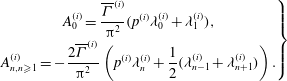









Appendix C. Functions related to vortex sheet
C.1. Original Wagner problem
Let
 $k^{(W)}(s,t)$
be the strength of the vortex sheet for the original Wagner problem. The total circulation of the vortex sheet can be expressed as
 $$\begin{eqnarray}\int _{0}^{V_{\infty }t}k^{(W)}(s,t)\text{d}s={\rm\pi}c_{A}V_{\infty }{\it\alpha}_{e}F^{(W)}({\it\tau}),\end{eqnarray}$$
where
 $F({\it\tau})$
is the Wagner function for circulation that satisfies the following short-time and large-time behaviours:
 $$\begin{eqnarray}F_{{\it\tau}\rightarrow 0}^{(W)}=\frac{2\sqrt{{\it\tau}}}{{\rm\pi}},\quad F_{{\it\tau}\rightarrow \infty }^{(W)}=1.\end{eqnarray}$$
Apart from the asymptotic behaviour defined by (C 2), there is no analytic solution of the original Wagner problem for intermediate time. Pitt Ford & Babinsky (Reference Pitt Ford and Babinsky2013) used the numerical data of Wagner to approximate
 $F^{(W)}$
as
 $F^{(W)}({\it\tau})\approx 0.9140-0.3151\text{e}^{-{\it\tau}/0.1824}-0.5986\text{e}^{-{\it\tau}/2.0282}$
, which yields
 $F^{(W)}({\it\tau})\rightarrow 2{\it\tau}$
for
 ${\it\tau}\rightarrow 0$
and thus does not match the asymptotic behaviour (C 2). In order to match the asymptotic behaviour (C 2), here we slightly modify their formula to
 $$\begin{eqnarray}F^{(W)}({\it\tau})\approx 1-0.8123\text{e}^{-\sqrt{{\it\tau}}/1.276}-0.188\text{e}^{-{\it\tau}/1.211}+0.32683\times 10^{-3}\text{e}^{-{\it\tau}^{2}/0.892}.\end{eqnarray}$$
Since
 $k^{(W)}(s,t)$
should meet the condition (2.11), we may put
 $k^{(W)}(s,t)=K(s-V_{\infty }t)$
. Thus
 $\int _{0}^{V_{\infty }t}K(s-V_{\infty }t)\text{d}s={\rm\pi}c_{A}V_{\infty }{\it\alpha}_{e}F^{(W)}({\it\tau})$
and it can be verified that
 $$\begin{eqnarray}k^{(W)}(s,t)={\rm\pi}V_{\infty }{\it\alpha}_{e}G^{(W)}\left({\it\tau}-\frac{s}{c_{A}}\right)=-\frac{L_{\infty }}{{\it\rho}c_{A}V_{\infty }}G^{(W)}\left({\it\tau}-\frac{s}{c_{A}}\right)\end{eqnarray}$$
with
 $G^{(W)}({\it\tau})\equiv \text{d}F^{(W)}({\it\tau})/\text{d}{\it\tau}$
. By (C 3), we have
 $$\begin{eqnarray}G^{(W)}({\it\tau})\approx \frac{8.0}{\sqrt{{\it\tau}}}\left(0.0398\text{e}^{-0.784\sqrt{{\it\tau}}}+0.0194\sqrt{{\it\tau}}\text{e}^{-0.826{\it\tau}}-9.16\times 10^{-5}{\it\tau}^{3/2}\text{e}^{-1.121{\it\tau}^{2}}\right).\end{eqnarray}$$
Now consider the lift force
 $L^{(W)}$
of the original Wagner problem, for which there are no additional vortices and the planar vortex sheet spreads over
 $0<s<V_{\infty }t$
. According to Fung (Reference Fung2002),
 $L^{(W)}$
can be represented as
 $$\begin{eqnarray}L^{(W)}={\it\Phi}^{(W)}({\it\tau})L_{\infty }\quad \text{(Wagner model)}\end{eqnarray}$$
and
 ${\it\Phi}^{(W)}({\it\tau})$
is the Wagner function for lift. The latter may be represented either by the Carrick approximation, which agrees within 2 % error with the numerical value of Wagner over the entire region
 $0<{\it\tau}<\infty$
,
 $$\begin{eqnarray}{\it\Phi}^{(W)}({\it\tau})=1-\frac{1}{2+{\it\tau}},\end{eqnarray}$$
or by the Jones approximation
 ${\it\Phi}^{(W)}({\it\tau})=1-0.165\text{e}^{-0.082{\it\tau}}-0.335\text{e}^{-0.64{\it\tau}}$
.
Consider
 ${\it\chi}={\it\chi}({\it\tau},{\it\tau}_{0},{\it\tau}_{1})$
defined by (2.22). Inserting the expression (C 4) for
 $k^{(W)}(s,t)$
into (2.22), we obtain
 $$\begin{eqnarray}\displaystyle {\it\chi}({\it\tau},{\it\tau}_{0},{\it\tau}_{1}) & = & \displaystyle \frac{1}{c_{A}}\int _{s_{1}}^{s_{0}}\frac{\displaystyle \sqrt{1+\frac{s}{c_{A}}}}{\displaystyle \sqrt{\frac{s}{c_{A}}}}\,G^{(W)}\left({\it\tau}-\frac{s}{c_{A}}\right)\text{d}s\nonumber\\ \displaystyle & = & \displaystyle \int _{{\it\tau}_{0}}^{{\it\tau}_{1}}\frac{\sqrt{1+{\it\tau}-m}}{\sqrt{{\it\tau}-m}}\,G^{(W)}(m)\text{d}m.\end{eqnarray}$$
Here we have used (2.1) for
 $s_{0}$
and
 $s_{1}$
.
C.2. Lift force component due to vortex sheet
Using (2.17c ), we have
 $$\begin{eqnarray}\frac{\text{d}{\it\Theta}_{b}^{(s)}}{\text{d}t}=-\frac{\text{d}}{\text{d}t}\int _{s_{1}}^{s_{0}}\left(s+c_{A}-\sqrt{sc_{A}+s^{2}}\right)k(s,t)\text{d}s+\frac{c_{A}}{2}\frac{\text{d}}{\text{d}t}\int _{s_{1}}^{s_{0}}\frac{\sqrt{c_{A}+s}}{\sqrt{s}}k(s,t)\text{d}s.\end{eqnarray}$$
Inserting this expression and the expression of
 ${\it\Gamma}_{b}^{(s)}$
defined in (2.16c
) into (2.17c
), and using the condition of zero lift force (2.11), we have
 $$\begin{eqnarray}\displaystyle L^{(s)} & = & \displaystyle {\it\rho}V_{\infty }\int _{s_{1}}^{s_{0}}k(s,t)\text{d}s+{\it\rho}\frac{\text{d}}{\text{d}t}\int _{s_{1}}^{s_{0}}\left(\sqrt{sc_{A}+s^{2}}-s\right)k(s,t)\text{d}s\nonumber\\ \displaystyle & & \displaystyle -\,{\it\rho}V_{\infty }\int _{s_{1}}^{s_{0}}\frac{\sqrt{c_{A}+s}}{\sqrt{s}}k(s,t)\text{d}s+{\it\rho}\frac{c_{A}}{2}\frac{\text{d}}{\text{d}t}\int _{s_{1}}^{s_{0}}\frac{\sqrt{c_{A}+s}}{\sqrt{s}}k(s,t)\text{d}s.\end{eqnarray}$$
When the condition (2.19) is used to replace
 $\int _{s_{1}}^{s_{0}}(\sqrt{c_{A}+s}/\sqrt{s})k(s,t)\text{d}s$
by
 $-{\it\Gamma}_{m}$
, the above equation reduces to
 $$\begin{eqnarray}L^{(s)}={\it\rho}V_{\infty }{\it\Gamma}_{m}-{\it\rho}\frac{c_{A}}{2}\frac{\text{d}{\it\Gamma}_{m}}{\text{d}t}+L_{{\it\phi}},\end{eqnarray}$$
where
 $L_{{\it\phi}}$
is defined by
 $$\begin{eqnarray}L_{{\it\phi}}={\it\rho}V_{\infty }\int _{s_{1}}^{s_{0}}k(s,t)\text{d}s+{\it\rho}\frac{\text{d}}{\text{d}t}\int _{s_{1}}^{s_{0}}\left(\sqrt{sc_{A}+s^{2}}-s\right)k(s,t)\,\text{d}s.\end{eqnarray}$$
It is clear that
 $L_{{\it\phi}}$
is the only term that explicitly depends on the vortex sheet. For the original Wagner problem (without additional vortices), we have
 $L^{(v)}=0$
,
 ${\it\Gamma}_{m}={\it\Gamma}_{\infty }$
(following (2.20)) and
 $\text{d}{\it\Gamma}_{m}/\text{d}t=0$
, and the use of (2.16), (2.25), (2.27) and (C 11) yields
 $$\begin{eqnarray}L^{(W)}=L_{{\it\phi}}^{(W)}={\it\rho}V_{\infty }\int _{0}^{V_{\infty }t}k^{(W)}(s,t)\text{d}s+{\it\rho}\frac{\text{d}}{\text{d}t}\int _{0}^{V_{\infty }t}\left(\sqrt{sc_{A}+s^{2}}-s\right)k^{(W)}(s,t)\text{d}s.\end{eqnarray}$$
Here we have inserted the superscript
 $(W)$
to mean original Wagner problem. This means that, for the original Wagner problem,
 $L_{{\it\phi}}$
is the total force. In this appendix C, we will recall some useful results for the original Wagner problem, for which the lift force and total circulation are simply given by
 $$\begin{eqnarray}L^{(W)}={\it\Phi}^{(W)}({\it\tau})L_{\infty },\quad \int _{0}^{V\infty t}k^{(W)}(s,t)\text{d}s=-{\it\Gamma}_{\infty }F^{(W)}({\it\tau}),\end{eqnarray}$$
where
 ${\it\Phi}^{(W)}({\it\tau})$
and
 $F^{(W)}({\it\tau})$
are Wagner functions for lift and circulation. Hence, by (C 13) and (C 14), we have
 $$\begin{eqnarray}{\it\Phi}^{(W)}({\it\tau})=\frac{{\it\rho}V_{\infty }}{L_{\infty }}\int _{0}^{V_{\infty }t}k^{(W)}(s,t)\text{d}s+\frac{{\it\rho}}{L_{\infty }}\frac{\text{d}}{\text{d}t}\int _{0}^{V_{\infty }t}\left(\sqrt{sc_{A}+s^{2}}-s\right)k^{(W)}(s,t)\text{d}s,\end{eqnarray}$$
which can be rewritten as
 $$\begin{eqnarray}{\it\rho}\frac{\text{d}}{\text{d}t}\int _{0}^{V_{\infty }t}\left(\sqrt{sc_{A}+s^{2}}-s\right)k^{(W)}(s,t)\text{d}s=({\it\Phi}^{(W)}({\it\tau})-F^{(W)}({\it\tau}))L_{\infty }.\end{eqnarray}$$
Now, for the present problem with additional vortices,
 $k(s,t)$
is not equal to
 $k^{(W)}(s,t)$
but is related to
 $k^{(W)}(s,t)$
by (2.23). Putting (2.23) into the force
 $L_{{\it\phi}}$
defined by (C 12), we obtain
 $$\begin{eqnarray}L_{{\it\phi}}={\it\rho}V_{\infty }\frac{{\it\Gamma}_{m}}{{\it\chi}{\it\Gamma}_{\infty }}\int _{s_{1}}^{s_{0}}k^{(W)}(s,t)\text{d}s+{\it\rho}\frac{\text{d}}{\text{d}t}\left(\frac{{\it\Gamma}_{m}}{{\it\chi}{\it\Gamma}_{\infty }}\int _{s_{1}}^{s_{0}}\left(\sqrt{sc_{A}+s^{2}}-s\right)k^{(W)}(s,t)\text{d}s\right).\end{eqnarray}$$
Following (C 15) for the original Wagner problem, we define two new functions
 ${\it\phi}({\it\tau},{\it\tau}_{0},{\it\tau}_{1})$
and
 ${\it\psi}({\it\tau},{\it\tau}_{0},{\it\tau}_{1})$
, called modified Wagner functions, by
 $$\begin{eqnarray}\left.\begin{array}{@{}c@{}}\displaystyle {\it\phi}({\it\tau},{\it\tau}_{0},{\it\tau}_{1})=\frac{{\it\rho}V_{\infty }}{{\it\chi}L_{\infty }}\int _{s_{1}}^{s_{0}}k^{(W)}(s,t)\text{d}s+\frac{{\it\rho}}{L_{\infty }}\frac{\text{d}}{\text{d}t}\left(\frac{1}{{\it\chi}}\int _{s_{1}}^{s_{0}}\left(\sqrt{sc_{A}+s^{2}}-s\right)k^{(W)}(s,t)\text{d}s\right)\!,\\ \displaystyle {\it\psi}({\it\tau},{\it\tau}_{0},{\it\tau}_{1})=\frac{2}{c_{A}{\it\Gamma}_{\infty }{\it\chi}}\int _{s_{1}}^{s_{0}}\left(\sqrt{sc_{A}+s^{2}}-s\!\right)k^{(W)}(s,t)\text{d}s.\end{array}\!\right\}\end{eqnarray}$$
Then (C 17) can be rewritten as
 $$\begin{eqnarray}L_{{\it\phi}}=-{\it\rho}V_{\infty }{\it\phi}({\it\tau},{\it\tau}_{0},{\it\tau}_{1}){\it\Gamma}_{m}-\frac{1}{2}{\it\rho}c_{A}{\it\psi}({\it\tau},{\it\tau}_{0},{\it\tau}_{1})\frac{\text{d}{\it\Gamma}_{m}}{\text{d}t}.\end{eqnarray}$$
The functions
 ${\it\phi}({\it\tau},{\it\tau}_{0},{\it\tau}_{1})$
and
 ${\it\psi}({\it\tau},{\it\tau}_{0},{\it\tau}_{1})$
defined by (C 18) are similar to
 ${\it\Phi}^{(W)}({\it\tau})$
defined by (C 15) and
 ${\it\Phi}^{(W)}({\it\tau})-F^{(W)}({\it\tau})$
, respectively (see (C 16)). For (C 18) the integral is defined over
 $s_{1}<t<s_{0}$
at the current time
 $t$
, while the integral in (C 15) and (C 16) is defined over
 $0<s<V_{\infty }t$
. In § C.3, we give the explicit expressions for these modified Wagner functions.
Putting (C 19) into (C 11) leads to the formula (2.29).
Modified Wagner functions for several values of
 ${\it\tau}_{0}$
.

C.3. Modified Wagner functions
Using (C 4) and with the help of (2.1), it can be verified that
 $$\begin{eqnarray}\displaystyle & & \displaystyle \displaystyle -\frac{{\it\rho}V_{\infty }}{L_{\infty }}\int _{s_{1}}^{s_{0}}k^{(W)}(s,t)\text{d}s=\displaystyle \int _{{\it\tau}_{0}}^{{\it\tau}_{1}}G^{(W)}(m)\text{d}m\nonumber\\ \displaystyle & & \displaystyle \qquad =\displaystyle \int _{{\it\tau}_{0}}^{{\it\tau}_{1}}\frac{\text{d}F^{(W)}(m)}{\text{d}m}\text{d}m=F^{(W)}({\it\tau}_{1})-F^{(W)}({\it\tau}_{0}),\end{eqnarray}$$
 $$\begin{eqnarray}\displaystyle & & \displaystyle \displaystyle -\frac{{\it\rho}V_{\infty }}{c_{A}L_{\infty }}\int _{s_{1}}^{s_{0}}\left(\sqrt{sc_{A}+s^{2}}-s\right)k^{(W)}(s,t)\text{d}s\nonumber\\ \displaystyle & & \displaystyle \qquad =\displaystyle \int _{{\it\tau}_{0}}^{{\it\tau}_{1}}\left(\sqrt{({\it\tau}-m)+({\it\tau}-m)^{2}}-({\it\tau}-m)\right)G^{(W)}(m)\,\text{d}m.\end{eqnarray}$$
 ${\it\phi}({\it\tau},{\it\tau}_{0},{\it\tau}_{1})$
and
 ${\it\psi}({\it\tau},{\it\tau}_{0},{\it\tau}_{1})$
:
 $$\begin{eqnarray}\displaystyle \displaystyle {\it\phi}({\it\tau},{\it\tau}_{0},{\it\tau}_{1})=\frac{1}{{\it\chi}({\it\tau},{\it\tau}_{0},{\it\tau}_{1})}(F^{(W)}({\it\tau}_{1})-F^{(W)}({\it\tau}_{0}))+\frac{1}{2}\frac{\text{d}}{\text{d}{\it\tau}}{\it\psi}({\it\tau},{\it\tau}_{0},{\it\tau}_{1}),\qquad \quad & & \displaystyle\end{eqnarray}$$
 $$\begin{eqnarray}\displaystyle \displaystyle {\it\psi}({\it\tau},{\it\tau}_{0},{\it\tau}_{1})=\frac{2}{{\it\chi}({\it\tau},{\it\tau}_{0},{\it\tau}_{1})}\int _{{\it\tau}_{0}}^{{\it\tau}_{1}}\left(\sqrt{({\it\tau}-m)+({\it\tau}-m)^{2}}-({\it\tau}-m)\right)G^{(W)}(m)\,\text{d}m. & & \displaystyle \nonumber\\ \displaystyle & & \displaystyle\end{eqnarray}$$
 $\int _{{\it\tau}_{0}}^{{\it\tau}_{1}}\cdot \,\text{d}m=0$
for
 $t<t_{0}$
and
 $\int _{{\it\tau}_{0}}^{{\it\tau}_{1}}\cdot \,\text{d}m=\int _{{\it\tau}_{0}}^{{\it\tau}}\cdot \,\text{d}m$
for
 $t_{0}<t<t_{1}$
. When
 ${\it\tau}_{0}=0$
and
 ${\it\tau}_{1}={\it\tau}$
, we recover the functions of the original Wagner problem, that is,
 ${\it\chi}({\it\tau},{\it\tau}_{0},{\it\tau}_{1})=1,~{\it\phi}({\it\tau},{\it\tau}_{0},{\it\tau}_{1})={\it\Phi}^{(W)}({\it\tau})$
and
 ${\it\psi}({\it\tau},{\it\tau}_{0},{\it\tau}_{1})={\it\Psi}^{(W)}$
with
 $$\begin{eqnarray}{\it\Psi}^{(W)}({\it\tau})=2\int _{0}^{{\it\tau}}({\it\Phi}^{(W)}({\it\tau})-F^{(W)}({\it\tau}))\text{d}{\it\tau}.\end{eqnarray}$$
In figure 13 we display the modified Wagner functions
 ${\it\phi}({\it\tau},{\it\tau}_{0},{\it\tau})$
and
 ${\it\psi}({\it\tau},{\it\tau}_{0},{\it\tau})$
for several values of
 ${\it\tau}_{0}$
. It is seen that both are decreasing functions of
 ${\it\tau}_{0}$
.



