I. INTRODUCTION
The attractiveness of white light-emitting diodes (LEDs), stemming from their energy savings in combination with high brightness, long operation lifetimes, and environmental protection, positions them as the prime general lighting technology for lighting, display, and scintillation applications.Reference Pimputkar, Speck, DenBaars and Nakamura1–Reference Lin, Xiao, Guo, Chan and Liu3 White LEDs, therefore, are promising candidates to substitute for the conventional solid-state lighting sources in the coming future. Phosphor-converted approach is recognized as the most common and efficient way to generate white LED devices by combining the RGB tricolor (red, green, and blue) phosphors with near-ultraviolet (near-UV) InGaN-based chips due to its high luminous efficiency, high color-rendering index, and tunable color temperature. High-performance white LEDs have been fabricated by combining blue phosphor BaMgAl10O17:Eu2+, green phosphor ZnS:Cu+,Al3+, and red phosphor Y2O2S:Eu3+ with near-UV LED chip. Unfortunately, the efficiency of the red phosphor Y2O2S:Eu3+ is much lower than that of the green and blue phosphors.Reference Sivakumar and Varadaraju4 In addition, this sulfide-based phosphor comes into being easily decomposed and causes poisonous gas as it contains toxic elements against strong irradiation and its lifetime is inadequate under the excitation of UV light.Reference Yan, Zhang, Zhang, Lu, Ren, Nie and Wang5,Reference Du, Sun, Xia and Sun6 Recently, Eu2+-doped nitrides have attracted more attention due to their high stability and high luminous efficiency. For example, Ca2Si5N8:Eu2+,Reference Li, van Steen, van Krevel, Botty, Delsing, DiSalvo, de With and Hintzen7 Sr2Si5N8:Eu2+,Reference Xie, Hirosaki, Sakuma and Kimura8 and MAlSiN3:Eu2+ (M = Ca, Sr)Reference Watanabe and Kijima9 red phosphors have been developed and improved. However, almost the nitrides above have to stand critical preparation conditions, such as high temperature, high N2 pressure, and air-sensitive starting powders, etc., which restrict the widespread use of nitride red phosphors. Therefore, it is an urgent task to search for a new red phosphor with high efficiency and excellent chemical stability under soft chemical methods. At present, most of fluorescent materials were prepared by the traditional solid-state method, which generally requires high temperature and grinding. The grinding process damages the phosphor surfaces, resulting in the decrease of luminescence intensity, and the aggregation and irregular shape are also unavoidable, which inhibit the absorption of the excitation energy and thereby reduce the luminescence intensity.Reference Pang, Lin and Yu10 Therefore, a simple and economical method for making high-quality phosphor is desirable. The Pechini method has some advantages over the conventional solid-state method, including easy stoichiometric control, good homogeneity, low-calcination temperature, and homogeneous distribution of particles.Reference Rao11
During the last decades, much attention has been paid on Eu3+ ions-adopted molybdate and tungstate compounds as potential red phosphors owing to energy transfer between  ${\rm{WO}}_{\rm{4}}^{{\rm{2}} - }$,
 ${\rm{MoO}}_{\rm{4}}^{{\rm{2}} - }$, or
 ${\rm{MoO}}_{\rm{6}}^{{\rm{6}} - }$ complexes and the rare earth ions.Reference Neeraj, Kijima and Cheetham12–Reference Zheng, You, Liu, Song, Jia, Huang, Yang, Zhang and Ning14 Remarkably, the excitation efficiency of Eu3+ in tungstates and molybdates at around 393 and 465 nm is prominently enhanced compared with that of Eu3+ in most hosts. Such an inset host dependence of Eu3+ leads to the excellent reproduction quality of optical prosperities for red phosphors especially in the process of mass production and in fabrication of power pc-LEDs with high junction temperature. These phosphors with good excitability in the near-UV region are only few, however. The fact for this phenomenon is due to the reason that the excitation lines via the characteristic f–f transition absorption of Eu3+ located at near-UV region are sharp, which just partially cover the emission wave length of the near-UV LEDs. In this case, it cannot be under excitation with the emission wave length from the near-UV LEDs efficiently.
It is known that hexavalent Mo and W are stabilized not in the primitive ABO3 perovskite structure but in the ordered double perovskite structure, A2IIBIIBVIO6, in which AII is an alkaline earth ion, BII, a divalent metal ion, such as Mg, Ca, Ni, and Cu, and BVI, a hexavalent Mo or W ion.Reference Shannon and Prewitt15 And the compounds adopt an ordered structure with the rock-salt arrangement BII and BVI ions.Reference Anderson, Greenwood, Taylor and Poeppelmeier16 In this paper, we synthesized a novel Ba2MgMoO6:Eu3+ orange-red phosphor by the gel–sol method and investigated the photoluminescence properties of this phosphor as model due to the simplicity of the crystal structure.
II. EXPERIMENTAL SECTION
A. Samples preparation
All the chemicals of (NH4)6Mo7O24·4H2O(AR), Eu2O3(99.99%), BaCO3(AR), MgO(AR), NH3·H2O, and citric acid were used as the starting materials without any further purification. Ba2MgMoO6:Eu3+ samples were prepared by the Pechini method for the first time in this paper. A procedure for the sample synthesis can be typically described as follows: stoichiometric amounts of Eu2O3, MgO, and BaCO3 were first dissolved in dilute nitric acid under vigorous stirring according to the chemical formulae. The excess nitrite acid was evaporated at 80–90 °C under heating. Subsequently, a certain amounts of citric acid were added to the solution as a chelating agent for the metal ions, and the molar ratio of total chelate metal cations to citric acid was 1:2. Meanwhile, stoichiometric amounts of (NH4)6Mo7O24 was dissolved to the solution. At the end, the pH value of the mixed solution was adjusted to 7–8 with dropwise of NH3·H2O solution with magnetic stirring, and the transparent solution was heated at 80 °C in a water bath to produce a brown transparent resin, and the resin was further dried at 120 °C in oven for 10 h. In the last step, the dried gel was annealed at different temperatures, such as 800, 850, 900, 950, 1000, and 1100 °C, etc., for 10 h.
B. Characterization of samples
The phase purity of the prepared phosphors was measured by an x-ray diffractometer with Cu Ka radiation (wave length = 0.15406 nm) at 36 kV tube voltage and 20 mA tube current. Diffuse reflection spectra were obtained by an UV-visible spectrophotometer (Shimadzu UV-2450, Kyoto, Japan) using BaSO4 as a reference. The excitation and emission spectra of all the samples were measured by a Hitachi F-7000 Fluorescence Spectrophotometer (Tokyo, Japan) equipped with a 150 W xenon lamp as excitation source. The testing conditions of the photoluminescence spectra are as follows: scan speed is 60 nm/min, delay time is 0.0 s, EX and EM slit is 2.5 nm, photo-multiplier (PMT) voltage is 400 V, and response time is 0.002 s.
III. RESULTS
A. Phase purity and crystal structure
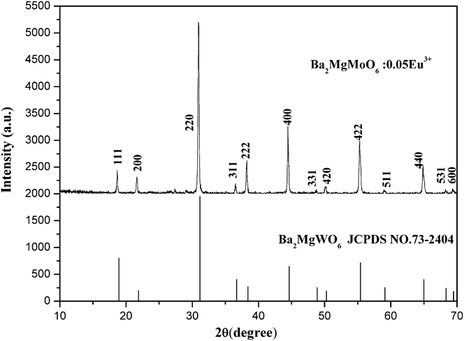
To characterize the phase purity and crystallinity of the as-prepared powder samples, the XRD patterns for all samples were examined. In the synthesis process, Ba2MgMoO6:Eu3+ were synthesized at different temperatures, such as 800, 850, 900, 950, 1000, and 1100 °C, etc., and it is found that the Ba2MgMoO6 compound could only be synthesized well at 1000 °C. Figure 1 shows the XRD pattern of the powder sample Ba2MgMoO6:5%Eu3+, which matches well the standard data of perovskite structure Ba2MgWO6 [Joint Committee on Power Diffraction Standards (JCPDS) card no. 22-0541], except for a very weak peak at 27.50°, which might be the diffraction peak of BaMoO4. Besides, the XRD patterns for other samples are identical to that of Ba2MgMoO6:5%Eu3+, and no extra impurity diffraction peaks are observed with different doping Eu3+ concentrations. This fact suggests that Eu3+ ions have been successfully built into the Ba2MgMoO6 host lattice and do not destroy the lattice structure of Ba2MgMoO6 host.
The XRD patterns of Ba2Mg0.95MoO6:0.05Eu3+ sample and the standard data of Ba2MgWO6 (JCPDS No. 73-2404).

The crystal structure of Ba2MgMo6, shown in Fig. 2, was covered to be a cubic system [space group Fm-3m (225)] with lattice constants a = b = c = 8.110 Å, α = β = γ = 90°, V = 533.4 Å3, and Z = 4, similar to the structure of (NH3)3FeF6, where Mg2+ and Mo6+ are ordered in alternate {111} cation layers.Reference Besse, Wathle and Baud17 There exist three different sites for the cations in Ba2MgMo6 host, viz. Ba located at the 8c (Td) site and Mg and Mo at the 4b (Oh) and 4a (Oh) sites, respectively.Reference Besse, Wathle and Baud17 The Eu3+ ions would substitute the Mg and Mo sites with an inversion center because the dominant lines (5D0 → 7F1) of the emission spectrum only correspond to an inversion center. Even though the ionic radii for Eu3+ (1.07 Å, eight-coordination) have an obvious gap compared with that for Mg2+ (0.89 Å, eight-coordination), it is much lager than that for Mo6+ (0.73 Å) in 6-fold coordination.Reference Su18 Thus, Eu3+ ions are expected to substitute for Mg2+ site ions in Ba2MgMoO6 host, and the chemical formula of Eu3+-doped Ba2MgMo6 can be the expression of Ba2Mg1−xMoO6:xEu3+. When Eu3+ ions are incorporated into Ba2MgMoO6 host, Eu3+ ions substitute for Mg2+ sites, which might induce the vacancy defect to compensate for the excess positive charge. As a consequence, the crystal lattice for Ba2MgMoO6 compound might exhibit slight deformation from cubic symmetry due to the nonequivalent substitution. The compound Ba2MgMoO6 is particularly suitable as model for fundamental studies of certain physical properties due to the simplicity of the crystal structure.
The crystal structure of Ba2MgMoO6 lattice.
B. Diffuse reflectance spectra of Ba2MgMoO6:Eu3+ phosphor
Figure 3 displays the diffuse reflectance spectrum of undoped Ba2MgMoO6 and Ba2Mg0.95MoO6:0.05Eu3+ samples in the spectral region from 200 to 800 nm at room temperature. It can be found that both Eu3+-free and Eu3+-doped samples exhibit the broad absorption band from 200 to 450 nm owing to the charge transfer (CT) transition from oxygen to molybdenum in MoO6 octahedra. In light of molecular orbital theory,Reference Shigeo and William19,Reference Blasse and Grabmaier20 the CT band is due to the electronic transition from the 2p orbital of O2− to the empty d orbital of Mo6+ in  ${\rm{MoO}}_{\rm{6}}^{{\rm{6}} - }$ groups. There is no selection rule that reduces the intensity, so the CT band is broad and large.
The diffuse reflection spectra of undoped Ba2MgMoO6 and Ba2Mg0.95MoO6:0.05Eu3+.
C. Photoluminescence properties of Ba2MgMoO6:Eu3+ phosphor
Figure 4 shows the excitation spectrum of Ba2Mg0.95MoO6:0.05Eu3+ phosphors monitored at 598 nm corresponding to 5D0 → 7F1 transition of Eu3+. Surprisingly, the excitation spectrum shows an intense broad band from 250 to 450 nm. This broad band is assigned to the CT from the oxygen ligands to the central molybdenum atom in  ${\rm{MoO}}_{\rm{6}}^{{\rm{6}} - }$ group. It is good agreement with the broad absorption band in the diffuse reflectance spectrum. There seems to be nonexistent of the characteristic excitation peaks of Eu3+. The reason for this phenomenon is resulting from the fact that the characteristic excitation peaks at about 396 nm must be overlapped by CT band. And the relative intensity of other f–f transitions of Eu3+ is much weaker than that of CT band. For this reason, the excitation spectrum comes out as shown in Fig. 4. The full width at half maximum (FWHM) of CT band is approximately 80 nm, which can cover the whole emission wave lengths (395–405 nm) of near UV LED chips (InGaN chip, λem = 400 nm).
Excitation spectrum of Ba2Mg0.95MoO6:0.05Eu3+ phosphor (λem = 598 nm).
Figure 5 displays the emission spectrum of Ba2Mg0.95MoO6:0.05Eu3+ phosphors under either CT band or 394 nm at room temperature. There exists one dominant emission peak corresponding to the parity-allowed magnetic dipole (MD) transition of 5D0 → 7F1 and the others are very weak as shown in Fig. 5. On the basis of the Judd-Ofeld theory,Reference Shigeo and William19 the electronic dipole (ED) transition 5D0 → 7F2 with ∆J = 2 would be dominant when Eu3+ ion occupied the lattice site without an inversion center and is hypersensitive while the MD transition 5D0 → 7F1 with ∆J = 1 is insensitive to the crystal field environment. Therefore, the intensity ratio of the transitions 5D0 → 7F1 to 5D0 → 7F2,
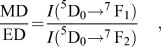 $${{{\rm{MD}}} \over {{\rm{ED}}}}{\rm{ = }}{{I{{\rm{(}}^{\rm{5}}}{{\rm{D}}_{\rm{0}}}{ \to ^{\rm{7}}}\,{{\rm{F}}_{\rm{1}}}{\rm{)}}} \over {I{{\rm{(}}^{\rm{5}}}{{\rm{D}}_{\rm{0}}}{ \to ^{\rm{7}}}\,{{\rm{F}}_{\rm{2}}}{\rm{)}}}}\quad ,$$
can be calculated to measure the symmetry of Eu3+ site. Obviously, the emission intensity of 5D0 → 7F1 transition is much higher than that of 5D0 → 7F2 transition, the value of MD/ED for Ba2Mg0.95MoO6:0.05Eu3+ sample is 8.4. This clearly indicates that Eu3+ ions mainly occupy the lattice site of symmetric environment in the Ba2MgMoO6 host. The result should come out as no surprise because Mg2+ sites for substituted Eu3+ have inversion symmetry in this case. It is noted that the most intensive emission at 598 nm is much narrow with a full width at half maximum less than 2 nm.
Emission spectrum of Ba2Mg0.95MoO6:0.05Eu3+ phosphor (λex = 394 nm).
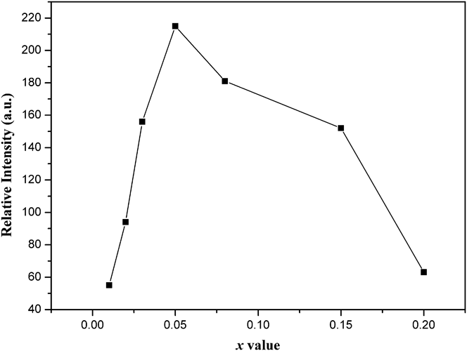
The effect of the Eu3+ doping concentration (x) in Ba2Mg1−xMoO6:xEu3+ (x = 0.01, 0.02, 0.03, 0.05, 0.08, 0.15, and 0.20) phosphors on the relative photoluminescence intensity at highest 5D0 → 7F1 transition is shown in Fig. 6. Generally speaking, a low doping concentration gives a weak emission and it is unfavorable to luminescent applications, whereas an overdoping ratio perhaps brings about quenching of the luminescence because the increase in the doping concentration results in the enhancement of nonradiative relaxation between the neighboring Eu3+ ions. The luminescence intensity of Ba2Mg1−xMoO6:xEu3+ phosphors enhances with the increase of the Eu3+ doping ratio and the maximum emission intensity appears at x = 0.05. When the Eu3+ doping ratio is higher above 0.05, the luminescence intensity would decrease. Therefore, the optimum doping concentration of Eu3+ in Ba2Mg1−xMoO6:xEu3+ phosphor is about 0.05. Apparently, a low concentration quenching occurs in Ba2MgMoO6:Eu3+. Quenching interactions between neighboring Eu3+ ion cannot maybe take place due to such a low doping Eu3+ concentration. So quenching correlates with the probability of pairing Eu3+ ions through intervening oxygens rather than with concentration.Reference Van Uitert and Iida21 And it depends upon the overlap of the wave function of the magnetic ions with those of a dumbbell-shaped p-orbital of an intervening oxygen ion. The closer the angle is to 180°, the stronger the interaction. In Ba2MgMoO6, the Ba–O–Ba angle is equal to 177.084°, and the Mg–O–Mg angle is about 115.734°or 180°. Thus, interactions between neighboring Eu3+ ions through intervening oxygens are involved in quenching. Dexter also pointed out that quenching may occur as a result of energy transfer by means of identical ions to one which acts as a sink due to its presence next to a defect.Reference Dexter and Schulman22 For Ba2MgMoO6:Eu3+, the lattice defects appear due to the nonequivalent substation. Hence, the Eu3+ ion next to the defect might lose the energy to the host structure through interaction with the phonon spectrum.
The photoluminescence intensity (integrated intensity of 5D0 → 7F1) of Eu3+ ions as a function of its doping concentration (x).
IV. DISCUSSIONS
A. CT state of Mo–O
As well is known that ligand and metal ions play prominent roles in CT transition in metal compounds. The CT excitation is an electronic transition from the ground state of ligand to the excited state of metal ions. The spectral position of the CT transition mainly depends on three factors: (i) the ionization potential of the d1 → d0 ionization, (ii) the number and nature of the ligands, (iii) the interaction between ions mutually in the lattice.Reference Blasse and Grabmaier20
In this work, we have studied the room temperature photoluminescence of undoped Ba2MgMoO6. There is no emission from MoO6 octahedra, which suggests that the emission is quenched at room temperature. The similar results are observed in the analogous compounds.Reference Sivakumar and Varadaraju23,Reference Bode and Van Oosterhout24 For Ba2Mg0.95MoO6:0.05Eu3+, the CT band is mainly due to the electronic transition from the 2p orbital of O2− to the empty d orbital of Mo6+ in  ${\rm{MoO}}_{\rm{6}}^{{\rm{6}} - }$ groups. This electronic transition is an allowed transition and no selection rules reduce its intensity. Hence, the CT band is strong and large compared with the spin and parity forbidden transitions of Eu3+. It is noted that the CT position of Ba2Mg0.95MoO6:0.05Eu3+ shifts into a lower energy region in comparison with that of CaMoO4:Eu3+. CaMoO4:Eu3+ with MoO4 tetrahedron has the central wave length of CT transition at 290 nm,Reference Mikhailik, Kraus, Miller, Mykhaylyk and Wahl25 whereas that of Ba2MgMoO6:Eu3+ with MoO6 octahedron is 390 nm. The reason for the shift of CT band to lower energy can be attributed to the increasing number of ligands (the oxygen ions) on condition that all other factors are equal. For the mixing of Mo6+ and O2− orbitals increasing in MoO6 octahedron, the energy required to transfer an electron from the O2− ion to the Mo6+ ion decreases and the CT band moves to lower energy.
B. Energy transfer from host to Eu3+ in Ba2MgMoO6:Eu3+
Energy transfer from the absorption groups to the Eu3+ ion is regulated by the exchange process, as argued by DexterReference Dexter26 and pointed out by Blasse and Bril.Reference Blasse and Bril27 The probability of this transfer is determined by the wave function overlap between the absorption group and the Eu3+ ions as well as energy overlap of the emission of the absorption group and the absorption levels of the Eu3+ ion.
To all appearance, the requirement of energy transfer is satisfied for Ba2MgMoO6:Eu3+. This is because the absorption group ( ${\rm{MoO}}_{\rm{6}}^{{\rm{6}} - }$) must emit a broad band in the short-wave length visible region, supposing that the emission was not quenched for Ba2MgMoO6 host at room temperature. The Eu3+ ion has some levels at 19,000; 21,500; and 23,900 cm−1 in the short-wave length visible region. Even if the emission of Ba2MgMoO6 is in the long-wave length visible region, there is some overlap with the 17,000-cm−1 level of the Eu3+ ion. In first approximation, the energy transfer from Ba2MgMoO6 host to Eu3+ ions depends on the wave function overlap, viz. orbital overlap, therefore. BlasseReference Blasse28 had presented much evidence that the overlap would be maximum if the angle of A/B-O-rare earth ion is 180°and least when the angle is 90°(A or B is the central of the absorption group). In the present case of Ba2MgMoO6:Eu3+ with cubic structure, the Mo–O–Eu angle is equal to 180°when the Eu3+ ions occupy the Mg site. This makes energy transfer from host to Eu3+ very facile due to the valid orbital overlap. This is the very reason why the emission (5D0 → 7F1) of Eu3+ dominates in the emission spectrum. However, when the Eu3+ is substituted at Ba site, the Mo–O–Eu angle is close to 90°, so energy transfer is not effective from host to Eu3+.
C. Near UV excitation
In the last few years, the CaMoO4:Eu3+ phosphor has attracted great interest due to its photoluminescent properties.Reference Hu, Zhuang, Ye, Wang, Zhang and Huang29–Reference Xie, Yuan, Hai, Wang, Wang and Li33 It is widely considered to be a promising red phosphor for near UV LEDs.Reference Tian, Qi, Wu, Hua and Chen13,Reference Hu, Zhuang, Ye, Wang, Zhang and Huang29,Reference Meng, Chen, Xu, Yang, Zhao, Di, Lu, Wang, Sun, Cheng, Yu and Peng34 As reported in previous work,Reference Hu, Zhuang, Ye, Wang, Zhang and Huang29 Eu3+-doped molybdate showed superior emission intensity than the conventional sulfide phosphor under excitation of 394 nm. To evaluate the merit of novel Ba2MgMoO6:Eu3+, we used the same excitation and make a comparison of emission intensity between the Ba2Mg0.95MoO6:0.05Eu3+and Ca0.76MoO4:0.24Eu3+. The Ca0.76MoO4:0.24Eu3+ was synthesized via the solid state, which was reported to display an optimum emission intensity according to Ref. Reference Hu, Zhuang, Ye, Wang, Zhang and Huang29. As depicted in Fig. 7, emission intensity of Ba2Mg0.95MoO6:0.05Eu3+ is on a par with that of Ca0.76MoO4:0.24Eu3+, although the Eu3+concentration of Ba2MgMoO6 is much less than that of CaMoO4. What's more, energy utilization efficiency of Ba2Mg0.95MoO6:0.05Eu3+ must be far higher than that of Ca0.76MoO4:0.24Eu3+. This is because the power is absorbed by broad excitation band for Ba2Mg0.95MoO6:0.05Eu3+ from the NUV chips. However, Ca0.76MoO4:0.24Eu3+ absorbs energy by the line excitation peak (the full width at half maximum is just 2.5 nm).
Excitation and emission spectra of Ba2Mg0.95MoO6:0.05Eu3+ and Ca0.76MoO4:0.24Eu3+ phosphor under 394-nm excitation.
Therefore, a conclusion can be made that Ba2MgMoO6:Eu3+ phosphor could be a promising red phosphor for near UV LEDs.
V. CONCLUSIONS
In summary, Ba2MgMoO6:Eu3+ is synthesized successfully by the Pechini method. An intense CT excitation band from 250 to 450 nm is observed in the near UV region. The FWHM of CT band and central wave length is approximately 80 and 394 nm, which can cover the whole emission wave lengths (395–405 nm) of near UV LED chips. A low concentration quenching occurs mainly due to the interactions of pairing Eu3+ ions through intervening oxygens in Ba2MgMoO6:Eu3+. The CT band of Mo–O is mainly due to the electronic transition from the 2p orbital of O2− to the empty d orbital of Mo6+ in  ${\rm{MoO}}_{\rm{6}}^{{\rm{6}} - }$ groups. Energy transfer from host to Eu3+ in Ba2MgMoO6:Eu3+ is very facile due to the valid orbital overlap. It has been found that Ba2MgMoO6:Eu3+ exhibits an intense orange-red emission under 394 nm excitation. Compared with CaMoO4:Eu3+, Ba2MgMoO6:Eu3+ could be a promising red phosphor for white LEDs under near-UV GaN-chips excitation.
ACKNOWLEDGMENT
This work is supported by the National Natural Science Foundation of China (Grant No. 21271049).