I. INTRODUCTION
For a few years, the choke horn has been used for downlink data-handling [Reference Ravanelli, Iannicelli, Baldecchi and Franchini1, Reference Jeon, Lee, Son, Lee, Lee and Lee2]. This antenna should often have both isoflux radiation pattern and circular polarization. In the coming years, the development of nanosatellite applications pushes the scientific community to do research on the X-band compact antennas. Unfortunately, an isoflux pattern and a compact antenna are often incompatible. One solution is to make a tradeoff between isoflux pattern quality and antenna size [Reference Arnaud, Duchesne, Elis, Fouany, Monediere and Thevenot3]. The maximum antenna dimensions were a diameter of 90 mm and a height of 20 mm above the 3 U nanosatellite platform (100 × 100 × 300 mm3). We have already conceived a compact choke horn antenna. Excellent results with an axial ratio (AR) lower than 3 dB and a realized gain (RG) higher than −2 dB at the limit of coverage (LOC) whatever azimuth angle (φ) over a 400 MHz radiation bandwidth (8.0–8.4 GHz) have been obtained except for the angle where the gain is maximum (θ = 35° instead 65°). However, the antenna feed is a 4-way divider with phase shifter (0, 90°, 180°, and 270°). This solution deteriorates the total efficiency and increases the antenna complexity. In this paper, a new electromagnetic feed is presented. It is made of a uniform circular helix antenna. It is organized as follows. First, Section II presents in simulation a comparison between several feeds and gives the best solution. It also deals with its association with the compact choke horn used in [Reference Arnaud, Duchesne, Elis, Fouany, Monediere and Thevenot3] on the 3 U platform. The comparison of measured and theoretical results is presented in Section III before a conclusion in Section IV.
II. ANTENNA DESCRIPTION
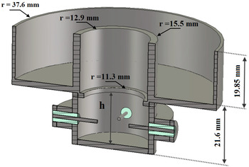
In [Reference Arnaud, Duchesne, Elis, Fouany, Monediere and Thevenot3], the global design of a compact choke horn fed with four coaxial probes spatially and temporally-shifted by 90° and placed in the same z-plane has been carried out. This design is based on the one from Brachat [Reference Brachat4] and scaled down to operate at 8 GHz. It has been optimized to obtain a good AR respecting the mechanical constraints. Figure 1 shows this antenna design with four coaxial probes but without the 4-way divider with phase shifter (0, 90°, 180°, and 270°). Now we have to replace this complex feed with a simpler one providing lower insertion losses and easier to realize. It is also essential to keep a good AR.
Design of the compact choke horn.

A) Comparison between several antenna feeds
All waveguide polarizers have a metallic or dielectric film in the middle of a waveguide, a sloped or stepped septum that are not suitable for this application because of their size. Three other feeds have been tested using CST Microwave Studio:
-
– Two coaxial probes
-
– Ring probe
-
– Helix antenna
1) TWO COAXIAL PROBES
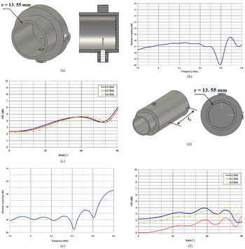
The simplest configuration is the case 1 which requires two coaxial probes, spatially and temporally-shifted by 90° at the central frequency (8.2 GHz), and placed in the same z-plane (Fig. 2(a)). The waveguide output has been extended by 20 mm for the establishment of the propagation modes. The AR radiation is then obtained. This configuration does not work properly because of the too high coupling between the probes (S21 > −20 dB) (Fig. 2(b)), which increases the AR in the φ = 0° cut-plane (Fig. 2(c)). This coupling, which can be either constructive or destructive, depends on the phase shift between the ports and results in a difference between the E θ and E φ electric field amplitudes [Reference Arnaud, Rodes, Thevenot, Chantalat and Monediere5]. It is therefore beneficial to add a guided wavelength (λ g ) between the coaxial probes (Fig. 2(d)) which will decrease the mutual coupling (S21 < −40 dB) (Fig. 2(e)). In this case 2, the AR is acceptable. However, this solution cannot be retained due to its size and its frequency dependence.
Case 1: two coaxial probes in the same z-plane (a), mutual coupling (b), simulated AR radiation patterns (φ = 0° plane) (c). Case 2: two coaxial probes in different z-planes (d), mutual coupling (e), simulated AR radiation patterns (φ = 0° plane) (f).

2) RING PROBE
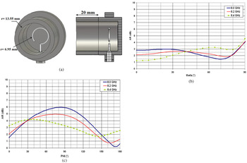
The design is based on the one from Kunpeng Wei [Reference Wei, Zhang, Zhao and Feng6] and scaled up to operate at 8 GHz (Fig. 3(a)). The waveguide output has been extended by 20 mm for the reasons aforementioned. Figure 3(b) presents the simulated AR radiation patterns (φ = 0° plane) and shows that this solution is not efficient. It is too sensitive to the frequency. Moreover, Fig. 3(c) shows the simulated AR patterns at θ = 65° versus the azimuth angle (φ). They depend highly on this azimuth angle. As a result, this feed cannot be kept for this study.
Design of ring probe (a), simulated AR radiation patterns (φ = 0 plane) (b), simulated AR at θ = 65° versus azimuth angle (c).

3) HELIX FEED
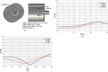
The helix antenna has been developed by Kraus in 1947 [Reference Volakis7]. Several configurations are possible (uniform, tapered end, continuous taper, non-uniform, etc.) with a single or several metallic conductors. In our case, a uniform circular helix feed has been designed with a single winding and turn to minimize the height (Fig. 4(a)). Figures 4(b)–4(c) show that the feed has correct performances of AR over a 400 MHz radiation bandwidth. This solution is kept for the following study. This feed will be associated with the compact choke horn used in [Reference Arnaud, Duchesne, Elis, Fouany, Monediere and Thevenot3] and installed on the 3 U platform simulating a nanosatellite to obtain the final structure.
Design of helix antenna (a), simulated AR radiation patterns (φ = 0° plane) (b), Simulated AR at θ = 65° versus azimuth angle (c).

B) Simulation of the whole antenna
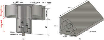
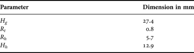
The helix feed is then installed into the horn input (Fig. 5(a)) and the whole antenna obtained on the 3 U platform is shown in Fig. 5(b). It is not possible to keep the helix parameters when it is associated with horn. Therefore, a new optimization has been made, by changing the value of the waveguide height (H g ), the helix conductor radius (R t ), the helix radius (R h ), and the helix height (H h ). The final dimensions are indicated in Table 1.
Simulation of the whole antenna (a), simulation of the whole antenna on the platform 3 U (b).

Parameter dimensions.

III. MEASUREMENT AND SIMULATION VALIDATION
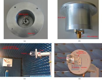
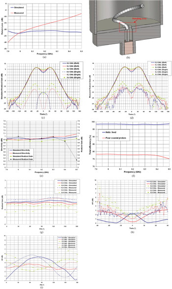
A prototype has been realized and measured in our Far-Field Antenna Test Range (Figs 6(a)–6(d)). Figure 7(a) shows a good matching over the desired radiation bandwidth. However, a difference appears between simulation and measurement. The matching antenna depends greatly on the mechanical accuracy of the helix and its positioning at the waveguide input (Fig. 7(b)). Figures 7(c)–7(d) show the left hand circular polarization (LHCP) and the right hand circular polarization (RHCP) radiation patterns (RG drawn in the φ = 0° cut-plane) in simulations and measurements. An isoflux shape over the entire frequency band is obtained but the RG is maximum at the θ = 35° angle instead of θ = 65°. This is the same for the antenna studied in [Reference Arnaud, Duchesne, Elis, Fouany, Monediere and Thevenot3]. The simulated and measured directivity are similar (Fig. 7(e)) in the studied bandwidth. The maximum RG are comparable over a 400 MHz bandwidth with a measurement tolerance of ±0.8 dB. We can see a real improvement on the total efficiency which is close to 100% (taking into account the measurement tolerance) instead of the 80% previously obtained in [Reference Arnaud, Duchesne, Elis, Fouany, Monediere and Thevenot3]. Figure 7(f) shows this comparison of the simulated total efficiency. The simulated RG is almost greater than 0 at the LOC whatever the azimuth angle (φ) instead of −2 dB in [Reference Arnaud, Duchesne, Elis, Fouany, Monediere and Thevenot3]. The measured RG is slightly lower than the simulated ones (Fig. 7(g)). On the other side, the horn changes the AR quality of the helix feed (Figs 7(h) and 7(i)). In the frequency band, the maximum AR is approximately 5 dB which is not suitable for such a space mission but for other ones less restrictive. Increasing the number of turns of the helix will improve this characteristic at the detriment of the antenna compactness [Reference Volakis7]. The AR measurement results are similar to the simulation up to θ = ± 50°. Beyond, the mechanical support effects such as the interface “antenna/motor” degrade this parameter.
View of the helix feed (front view) (a), view of the helix feed (bottom view) (b), photography of the manufactured antenna positioned on our antenna test range support (c), photography of the manufactured antenna positioned on our antenna test range support (zoom) (d).

Return loss (a), matching area (b), simulated RHCP and LHCP radiation patterns (φ = 0° plane) (c), measured RHCP and LHCP radiation patterns (φ = 0° plane) (d), directivity and maximum RG (e), simulated total efficiency (f), RG at θ = 65° versus azimuth angle (g), AR radiation patterns (φ = 0° plane) (h), AR at θ = 65° versus azimuth angle (i).

IV. CONCLUSION
This paper completes previous work on an X-band compact choke horn antenna with circular polarization and isoflux pattern for nanosatellite applications. The feed of this last one was made of four coaxial probes requiring the use of a 4-way divider with phase shifter (0, 90°, 180°, and 270°). The insertion losses of this device degrade the total efficiency and it increases the realization complexity. A new antenna feed using a uniform circular helix antenna has been proposed and applied to the design. Excellent numerical results have been obtained with a total efficiency close to 100% on the 8.0–8.4 GHz frequency band. On the other side, the simulated AR quality is less efficient than the first case, about 5 dB instead of 3 dB on the LOC whatever the azimuth angle (φ). This kind of antenna is suitable for missions less restrictive than the one developed here. A prototype has then been realized to demonstrate the feasibility of such a structure. The measurement results are in excellent agreement with the theoretical ones.
ACKNOWLEDGMENT
The authors would like to thank Centre National d'Etudes Spatiales (CNES) – FRANCE who has financially supported this study.
 Eric Arnaud was born in France in 1970. He received the Diplôme D'Etudes Supérieures Specialisées (DESS) and Ph.D. degrees in Electronics and Telecommunication from the University of LIMOGES in 1994 and 2010, respectively. He did his Ph.D. on circularly polarized EBG antenna. From 1996 to 2001, he was in charge of the Microwave part of Free-Electron Laser (L.U.R.E). Since 2001, he has been in charge of XLIM laboratory's antenna test range. He participated in several research projects related to the design, development, and characterization of antennas. His research interests are mainly in the fields of circularly polarized EBG antenna, agile electromagnetic band gap matrix antenna, and isoflux pattern antenna.
 Luc Duchesne has 20 years of experience in engineering design and technical management, much of it spent in the field of RF front-end subsystems, antennas, and antenna measurement systems. He graduated from the French engineering school SupAero in 1994, receiving a Master's degree in Aerospace Electronics. He joined the Antenna Department of the industrial company DASA (now EADS in Munich, Germany) as an RF design engineer where he took part in several product developments in the area of satellite antennas. Since 2000, he is working at SATIMO as Director of the Research & Development department, where he has led the development of several innovative antenna measurement systems based on the fast multi-probe techniques. Today, he is leading developments in new areas of applications for microwaves such as Non Destructive Testing. He is author of technical papers and patents in the fields of antennas, antenna measurement systems, and non-destructive testing.
 Kevin Elis was born in Carcassonne, in 1982. He received the master degree from the Paul Sabatier University of Toulouse, France, in 2009, and the Ph.D. degrees in Electromagnetism and High-Frequency systems from the University of Toulouse, in 2012. From January 2013 to March 2013, he worked with TELECOM/EMA research group, ENAC (French National Civil Aviation School), on RFC and ray techniques. Since April 2013, he is antenna engineer (Telemetry/Telecommand and SIGINT antennas) in the Antennas department of the CNES (French National Space Center), Toulouse.
 Jamil Fouany was born in Lebanon, in 1989. He received the Master's degree in Electronic and Optical Engineering for High-Frequency Communications (IXEO) from the University of Limoges, France in 2012. He is currently toward the Ph.D. degree in High Frequency Communications, photonics and systems in the XLIM Laboratory, University of Limoges. His research interests include parasitic antennas with circular polarization.
 Thierry Monediere was born in 1964 in Tulle (France). He obtained his Ph.D. in 1990 in the IRCOM Laboratory of the University of Limoges. He is actually the head of department “Waves and Associated Systems” of Xlim laboratory and Professor in the University of Limoges. He develops his research activities in Xlim Laboratory (UMR CNRS/University of Limoges). He works on multifunction antennas, EBG antennas, and also active antennas.
 Marc Thevenot was born in Limoges, France, in February 1971. He received the BS and M.Sc. degrees in Microwaves from the University of Limoges, France, in 1995. He received the Ph.D. Degree in Electronic from the University of Limoges in 1999. He joined the CNRS in 2001. He is responsible of multifunction antennas activities in the “Waves and Associated Systems department of Xlim. His main present research activities deal with the electromagnetism, EBG antennas, materials, parasitic element antennas, reconfigurable antennas, and reflectarray antennas.”