1. Introduction
As the population ages, there is a decline in the physical capabilities of the elderly, notably a decrease in their ability to walk, increasing the demand for mobility-assisting medical devices. Lower limb exoskeleton robots, as intelligent mechatronic systems, effectively assist elderly individuals with limited mobility through human-computer interaction technology, aiding them in performing daily activities such as climbing stairs and providing support on uneven terrain.
Beyond healthcare, exoskeleton robots also play a role in military and rescue operations, enhancing strength and endurance to allow soldiers to carry heavy equipment and adapt to complex environments. In labor-intensive industries, they reduce the physical strain on workers, improve efficiency, and lower the risk of work-related injuries [Reference Xue, Wang, Zhang, Zhang and Li1]. Joint actuation control lies at the heart of precise movement in exoskeleton robots, and devising control strategies for diverse application scenarios presents a significant research challenge, as shown in Figure 1. The adaptive robust control algorithm proposed in this paper aims to enhance the dynamic performance and stability of hip-assist exoskeleton robots, catering to the walking needs of a variety of users.
Wearing a hip-assist exoskeleton robot.

The drive control of exoskeleton robots is fundamental to ensuring stability and precise positional control. Given the complexity of their structure, mere low-level control is insufficient for the coordinated actuation required in complex operational environments [Reference Xue, Wang, Zhang, Zhang and Li2]. Therefore, it is essential to integrate advanced upper-level control strategies into the exoskeleton robot’s control system. This integration will enhance the robot’s motion accuracy, adaptability, and safety, thereby expanding its range of applications and increasing its value. Disc motors, noted for their torque richness, swift reactions, and space-saving form, optimally power the joints in these exoskeletons. Their design allows concentration of high power in a small area, key to creating sturdy and compact mechanisms for hip-assist devices. Disc motors’ efficiency and quiet operation both contribute to better device performance and a more pleasant user experience [Reference Wu, Wang, Du and Zhang3]. With ongoing technological progress, the integration of disc motors in such exoskeletons is likely to broaden, promising more sophisticated and effective support for elderly mobility. Such advancements may notably improve the elderly’s daily living standards and overall well-being [Reference Wei, Zha, Xia, Gu and Lin4].
Development of these robots’ joint mechanisms faces uncertainties due to variations in system parameters and external elements. Uncertainties in motor specifications, such as torque constants and inertia, along with the gear ratios of harmonic drive reducers, can lead to discrepancies from projected models [Reference Zhang, Tran and Huang5]. Moreover, the joint dynamics can be affected by external variables, including shifting loads, unstable temperatures, and operational inconsistencies. As these factors can impact the dynamic performance of the joint units, ongoing research aims to refine control strategies to ensure reliable and consistent operation of hip-assist exoskeleton robots [Reference Zhang, Nalam, Tu, Li, Si, Lewek and Huang6].
In classical control theory, PID control is widely recognized for its effectiveness in servo control systems, attributed to its straightforward structure and ease of parameter tuning [Reference Zhen, Zhao, Liu, Chen, Zhao and Chen7]. Despite its long-standing success, PID control faces challenges when applied to modern servo systems that demand high dynamic response speeds, precise steady-state accuracy, and superior disturbance rejection capabilities [Reference Ha, Lee and Park8]. These systems often require control strategies that offer enhanced nonlinear compensation and improved parameter robustness.
Currently, several advanced control strategies have been explored for servo control systems. One such approach is Active Disturbance Rejection Control (ADRC). ADRC employs an extended state observer to estimate and compensate for disturbances in real-time [Reference Khaled, Akhrif and Bonev9]. A key advantage of ADRC is its reduced reliance on precise mathematical models [Reference Zhong, Huang and Guo10]. However, its practical application can be influenced by the balance between observer bandwidth and noise sensitivity, and its multi-parameter coupling may require careful tuning [Reference Li, Ai, Gao and Tian11].
Sliding mode control is known for its ability to ensure finite-time convergence of system states through predefined sliding surfaces [Reference Rsetam, Cao and Man12]. This method offers strong robustness by effectively suppressing matched disturbances. Yet, the high-frequency oscillations associated with switching functions can lead to chattering, which may accelerate actuator wear and potentially excite unmodeled dynamics [Reference Aswani, Gonzalez, Sastry and Tomlin13]. These characteristics present considerations for its use in high-precision servo systems.
Predictive control is another strategy that addresses multi-constrained problems by employing receding horizon optimization [Reference Zeng, Mohammad, Madrigal, Axinte and Keedwell14]. Its effectiveness is closely tied to the accuracy of the prediction model. In applications sensitive to time delays, such as hip-assist exoskeletons, there is a notable trade-off between the algorithm’s real-time performance and dynamic response. Achieving precise acceleration tracking remains a challenge in these scenarios [Reference Wang, Wei, Yeboah, Li and Gao15].
To ensure precise trajectory following and robust dynamic reactions in the unpredictable nonlinear dynamics of systems like hip-assist exoskeleton robots, we’ve crafted a resilient control strategy founded on a definitive model, termed fractional-order hybrid PD (FHPD) control. This approach, while maintaining a straightforward architecture, delivers reliable control outcomes despite the presence of system uncertainties [Reference Zhao, Wu and Chen16, Reference Hwang, Park, Jin and Kang17]. The deterministic robust control system we’ve introduced effectively tackles and regulates these uncertainties through the strategic use of the joint module’s elements and design specifications.
Our framework initially categorizes system behavior into predictable and probabilistic segments, addressing joint module uncertainties within a bounded function. We integrate robust deterministic techniques with PID control, ensuring alignment with the system’s kinetic properties and resilience against unmodeled dynamics and parameter variations. Utilizing Lyapunov methods [Reference Qin, Zhao, Zhen, Sun and Zhang18, Reference Dawson, Qin, Gao and Fan19], we establish the controller’s stability, offering a simpler and more resource-efficient design suitable for constrained engineering applications.
This paper is structured into sections that cover the joint module’s nonlinear dynamics [Reference Yao and Jiang20], the development and stability analysis of our robust control approach, comparative performance evaluations with PID and MPD controllers, and a conclusion summarizing key research outcomes.
2. Dynamic system modeling
In the domain of dynamic assessment [Reference Moreno-Valenzuela, Quevedo-Pillado, Pérez-Aboytes and González-Hernández21], the hip-assist exoskeleton robot’s joint module is conceptualized as a composite unit, featuring a harmonic drive reducer coupled with a disc motor. Equation (1) captures the mathematical essence of the disc motor’s dynamics:
 \begin{align} \begin{cases}\dot {{i}_{d}}= -\dfrac {R}{{L}_{d}}{i}_{d}+ \dfrac {{L}_{q}}{{L}_{d}}{n}_{p}\dot {q}{{i}_{q}}+ \dfrac {{u}_{d}}{{L}_{d}}\\[6pt] \dot {{i}_{q}}= -\dfrac {R}{{L}_{q}}{i}_{q}-\dfrac {{L}_{d}}{{L}_{q}}{n}_{p}\dot {q}{{i}_{d}}-{n}_{p}\dot {q}\dfrac {{\varPsi }_{f}}{{L}_{q}}+ \dfrac {{u}_{q}}{{L}_{q}} \\[6pt] \ddot {q}=\dfrac {{T}_{e}}{J}-\dot {q}\dfrac {B}{J}-\dfrac {{T}_{p}}{J} \end{cases} \end{align}
Within the scope of this study, the variables
 ${i}_{d}$
and
 ${i}_{q}$
are indicative of the stator currents along the direct and quadrature axes, respectively. Correspondingly,
 ${u}_{d}$
and
 ${u}_{q}$
, denote the stator voltages in the d-axis and q-axis directions. The inductances of the stator along these axes are represented by
 ${L}_{d}$
and
 ${L}_{q}$
. The term
 ${n}_{p}$
signifies the count of pole pairs,
 $\omega$
symbolizes the angular velocity of the rotor, and
 ${\varPsi }_{f}$
refers to the flux linkage in the rotor. The stator resistance is denoted by
 $R$
. Furthermore, parameters
 $ B$
,
 ${T}_{e}$
, and
 ${T}_{p}$
are associated with the mechanical dynamics of the disc motor, relating to rotational inertia, damping due to viscosity, the torque generated by electromagnetic force, and the torque applied by the load, respectively.
Upon examining Eq. (1), it becomes evident that there is a nonlinear relationship between the speed and armature current of the disc motor. By decoupling Eq. (1), the derivation of the electromagnetic torque
 ${T}_{e}$
is presented as follows:
 \begin{equation} {T}_{e} =\frac {3}{2}{n}_{p}{i}_{p}\left [ {\psi }_{f}+({L}_{d}-{L}_{q}){i}_{d}\right ] \end{equation}
In the propulsion system of a disc motor, the Field-Oriented Control (FOC) technique is extensively applied. By aligning the vector sum of the three-phase stator currents along the q-axis, the d-axis current
 ${i}_{d}$
is nullified, with the q-axis current
 ${i}_{q}$
equating to the total current
 ${i}_{s}$
. Controlling the q-axis current
 ${i}_{q}$
in accordance with the principles of FOC allows for direct influence over the electromagnetic torque, which in turn optimizes dynamic responses due to the autonomous regulation of torque. The mathematical model for an embedded disc motor is delineated in Eqs. (3) and (4), serving as the theoretical foundation. For the surface-mounted disc motor used in experiments, it is assumed that the d-axis and q-axis inductances
 ${L}_{d}$
and
 ${L}_{q}$
are equal, collectively denoted as L. Thus, the mathematical model characterizing the surface-mounted disc motor is as follows:
 \begin{align} \begin{cases}{\dot {i}}_{d}=0 \\[4pt] {\dot {i}}_{q}=-\dfrac {R}{{L}_{q}}{i}_{q}-{n}_{p}\dot {q}\dfrac {{\psi }_{f}}{{L}_{q}}+\dfrac {{u}_{d}}{{L}_{d}} \\[4pt] \ddot {q}=\dfrac {\tau }{J}-\dot {q}\dfrac {B}{J}-\dfrac {{T}_{q}}{J} \end{cases} \end{align}
The expression for the electromagnetic torque
 ${T}_{e}$
is as follows:
 \begin{equation} {T}_{e} =\frac {3}{2}{n}_{p}{\psi }_{f}{i}_{q}={K}_{n}{i}_{q} \end{equation}
Within this framework,
 ${K}_{n}$
is designated as the constant of torque. By examining Eq. (3), the motion equation for the disc motor is articulated in the subsequent manner:
 \begin{equation} J\ddot {q}+B\dot {q}+{T}_{p}={T}_{e} \end{equation}
The movement of the manipulator’s joints is regulated by the motor’s output shaft through a harmonic drive reducer. The focus is on examining the operational transmission efficiency and the gear ratio of the reducer. The dynamic equation for the harmonic drive reducer can be succinctly represented as follows:
 \begin{equation} {T}_{N}=\mu \eta {T}_{p} \end{equation}
The constants
 $\mu$
and
 $\eta$
correspond to the gear ratio and the efficiency of the harmonic drive reducer, respectively.
 ${T}_{N}$
signifies the torque that the load imparts on the joint assembly. After integrating Eqs. (5) and (6) and taking into account the friction forces present in the harmonic drive reducer, the dynamic equation for the joint assembly is derived as follows:
 \begin{equation} J\ddot {q}+B\dot {q}+\frac {{T}_{N}}{\mu \eta }+{T}_{f}={T}_{e} \end{equation}
Within the harmonic drive reducer, the nonlinear frictional torque
 ${T}_{f}$
has a decisive impact on the dynamic performance of the joint module. The academic community continues to work on developing mathematical models of friction forces, aiming to more accurately assess the specific impact of these forces on the overall performance of mechanical systems, and has proposed various models to mitigate their adverse effects. In this study, we focus on introducing two types of friction models [Reference Marques, Flores, Claro and Lankarani22]: first, the widely recognized standard Coulomb friction model, followed by an optimized Stribeck model that incorporates factors such as initial friction, Coulomb friction, viscous resistance, and velocity transitions to more comprehensively reflect the friction characteristics within the joint module. Next, the key features of the standard Coulomb viscous friction model will be further elaborated [Reference Pennestr‘ı, Rossi, Salvini and Valentini23]:
 \begin{equation} {T}_{f}={f}_{b}\dot {q}+{f}_{d}sgn(\dot {q}) \end{equation}
The improved Stribeck friction model is articulated as follows [Reference Shao, Liu, Wang, Zhang and Yang24]:
 \begin{equation} {T}_{f}=\left [ {f}_{d}+({f}_{s}-{f}_{d}){\theta }^{-{(\frac {\dot {q}}{\dot {q}s} )}^{2}}\right ]sgn(\dot {q})+{f}_{b}\dot {q}-{f}_{g} \end{equation}
In the formula,
 ${f}_{b}$
represents the parameter for viscous friction,
 ${f}_{d}$
denotes the parameter for Coulomb friction, and
 ${f}_{s}$
is the parameter for static friction. The symbol
 $\dot {q}s$
is associated with the measure of lubrication. To counteract the irregular variations in frictional force that may occur during changes in the direction of motion, the element
 ${f}_{g}$
is incorporated into the model, the detailed function of which will be further elaborated in subsequent discussions:
 \begin{align} \begin{cases} {f}_{g}=s{\theta }^{-\frac {{\dot {q}}^{2}}{v}} \\[3pt] s=sgn \big(\dfrac {\dot {q}}{a} \big){f}_{s}+{f}_{d}l \\[3pt] v=a{\dot {q}}_{s}(d*sgn(a)+c*sgn(\dot {q})) \end{cases} \end{align}
In this context,
 $l$
,
 $d$
and
 $c$
represent the gain factors, while
 $a$
corresponds to the acceleration
 $\ddot {q}$
. The subsequent steps illustrate the transformation of Eq. (7) into its Lagrangian formulation:
 \begin{equation} E(q,t)\ddot {q}+I(q,\dot {q},t)\dot {q}+G(q,\dot {q})+F(q,\dot {q},t)=\tau (t) \end{equation}
where
 \begin{equation} \begin{cases}E= \dfrac {J}{K_{n} } \\I = \dfrac {B}{K_{n} } \\G=0 \\F = \dfrac {T_{n}}{\mu \eta }+ {T}_{f} \\\tau =i_{q} \end{cases} \end{equation}
Given that the subject of our study is a solitary disc motor, functioning as a mechanical system with a single degree of freedom, the variable in question is unidimensional. As the disc motor is designed for rotational movement only, the function G(
 $\cdot$
) equates to zero.
3. The robustly designed control system
3.1. The development of a resilient control framework
Our aim is for the mechanical system to accurately follow the preset trajectory
 ${q}^{d}\left ( t\right )$
with a desired swift velocity
 $\dot {{q}^{d}}\left ( t\right )$
, assuming
 ${q}^{d}\left ( t\right )$
is defined on [
 ${t}_{0}$
,
 $ \infty$
] with continuous second-order differentiability, and both
 ${q}^{d}\left ( t\right )$
, its first derivative
 $\dot {{q}^{d}}\left ( t\right )$
, and second derivative
 $\ddot {{q}^{d}}\left ( t\right )$
are uniformly bounded:
 \begin{align} \begin{cases}\theta (t)=q(t)-{q}^{d}(t) \\[3pt]\dot {\theta }(t)=\dot {q}(t)-{\dot {q}}^{d}(t) \\[3pt]\ddot {\theta }(t)=\ddot {q}(t)-{\ddot {q}}^{d}(t) \end{cases} \end{align}
Let:
 \begin{equation} \widetilde {\theta }(t)={\left [ \theta (t)\dot {\theta }(t)\right ]}^{T} \end{equation}
Our objective is to ensure that the system’s state variable
 $\widetilde {\theta }(t)$
remains uniformly bounded under the control of the developed controller and ultimately achieves uniform ultimate boundedness. The dynamics of the joint module, as defined by Eq. (11), can be reconceptualized as follows:
 \begin{equation} E({\ddot {q}}^{d}(t)+\ddot {\theta }(t))+I({\dot {q}}^{d}(t)+\dot {\theta }(t))+F=\tau (t) \end{equation}
In fact, due to the uncertainty and variability of parameters, as well as the dynamic characteristics not fully described by the model, the system inherently contains uncertainty. Therefore, the dynamic model can be decomposed into a standard part and an uncertain part. The division of the functions
 $E\left ( \cdotp \right )$
,
 $I\left ( \cdotp \right )$
and
 $F\left ( \cdotp \right )$
can be understood in the following manner:
 \begin{equation} \begin{matrix}E(q,\sigma ,t)=\overline {E}(q,t)+\triangle E(q,\sigma ,t) \\[3pt] I(q,\dot {q},\sigma ,t)=\overline {I}(q,\dot {q},t)+\triangle I(q,\dot {q},\sigma ,t) \\[3pt] F(q,\dot {q},\sigma ,t)=\overline {F}(q,\dot {q},t)+\triangle F(q,\dot {q},\sigma ,t) \end{matrix} \end{equation}
In this context,
 $\overline {E}\left ( \cdotp \right )$
,
 $\overline {I}\left ( \cdotp \right )$
and
 $\overline {F}\left ( \cdotp \right )$
denote the baseline components, whereas the variations
 $\varDelta E$
,
 $\varDelta I$
and
 $\varDelta F$
signify the oscillating elements correlated with
 $\sigma$
.
Subsequently, the estimated range of uncertainty and external disturbances is denoted by the variable
 $ \rho$
. For a given positive value of S, the scalar function
 $ \rho$
is chosen in a manner that:
 \begin{equation} \left \| \phi (\theta ,\dot {\theta },\sigma ,t)\right \|\leqslant \rho (\theta ,\dot {\theta },\sigma ,t) \end{equation}
where:
 \begin{align} \phi (\theta ,\dot {\theta },\sigma ,t) &=-\triangle E(q,\sigma ,t)({\ddot {q}}^{d}-S\dot {\theta })-\triangle I(q,\dot {q},\sigma ,t)({\dot {q}}^{d} -S\theta)\nonumber \\ &\quad -\triangle F(\dot {q},\sigma ,t) \end{align}
The subsequent goal is to devise an efficient control strategy
 $\tau (t)$
that ensures the tracking error is confined within predefined limits. We can utilize an algorithm to guarantee the desired performance constraints [Reference Tang, Sun, Li and Song25]. With a positive value of
 $\epsilon$
(typically small) and positive tuning coefficients
 ${k}_{p}$
and
 ${k}_{v}$
, the control law for the nonlinear system can be derived as follows:
 \begin{equation} \tau (t)=\overline {E}({\ddot {q}}^{d}-S\dot {\theta })+\overline {I}({\dot {q}}^{d}-S\theta )+\overline {F}-{K}_{p}\theta -{K}_{v}\dot {\theta }+p(\theta ,\dot {\theta },t) \end{equation}
where
 \begin{align} p(\theta ,\dot {\theta },t)=\begin{cases} -\dfrac {\varphi (\theta ,\dot {\theta },t) }{\epsilon }\rho (\theta ,\dot {\theta },t),& if\left \|\varphi (\theta ,\dot {\theta },t) \right \|\leqslant \epsilon \\[7pt] -\dfrac {\varphi (\theta ,\dot {\theta },t) }{\left \|\varphi (\theta ,\dot {\theta },t) \right \|}\rho (\theta ,\dot {\theta },t),& if\left \|\varphi (\theta ,\dot {\theta },t) \right \|\gt \epsilon \end{cases} \end{align}
 \begin{equation} \varphi (\theta ,\dot {\theta },t)=(\dot {\theta }+S\theta )\rho (\theta ,\dot {\theta },t) \end{equation}
 \begin{equation} {K}_{p}=diag{\left [ {K}_{pi}\right ]}_{n*n} \end{equation}
 \begin{equation} {K}_{v}=diag{\left [ {K}_{vi}\right ]}_{n*n} \end{equation}
Through in-depth analysis, our proposed model-based PD robust control framework demonstrates a design that relies on accurate system modeling and fully leverages the advantages of the PID control mechanism. The proportional adjustment component of the controller is designed to neutralize external disturbances and system uncertainties, with its piecewise design effectively preventing an excessive increase in robustness as the control signal decreases. This theoretical framework suggests that the FHPD controller surpasses standard PID and MPD controllers in terms of dynamic response. Figure 2 comprehensively displays the controller configuration, explaining how model-driven components and the PD feedback loop work together to reduce the discrepancy between the target and actual positions. In addition, the proportional component effectively alleviates uncertainties from the mechanical system and external disturbances, significantly enhancing the system’s dynamic performance.
Proposed FHPD robust control architecture diagram.

After structural analysis of the proposed controller, its advantages can be rephrased as follows:
-
1. Our algorithm, an extension of the traditional PD control, simplifies the complexity of parameter adjustment for engineering applications, enhancing its practicality.
-
2. The algorithm not only streamlines the parameter tuning process but also demonstrates robustness against uncertainties in parameters and external disturbances.
-
3. With a design that emphasizes simplicity and ease of implementation, the controller requires minimal hardware resources, making it suitable for a variety of mechanical systems with common embedded chips.
The design process of the PD robust controller for the joint module system can be re-articulated as:
Step one: Establish the dynamic equation of the joint module system using the Lagrangian approach.
Step two: Determine the upper bounds of external disturbances and uncertainties within the system, and calculate the scalar function q through Eq. (17).
Step three: Construct a piecewise function for q based on Eqs. (20) and (21).
Step four: Develop a model-based PD robust control method according to Eq. (19).
Considering the comprehensive analysis of the controller and its design process, it is notable that our proposed controller, with its low hardware requirements and ease of adjusting control parameters, is not only applicable to motor-driven systems but can also be rapidly adapted and integrated into various types of mechanical systems to achieve the desired motion control effects.
3.2. Stability analysis
Theorem. The controller (19) maintains the joint module’s error term
 $\widetilde {\theta }\left ( t\right )$
within a predefined boundary and ensures its convergence to a steady state within this boundary. The selection of an appropriate value for
 $\epsilon$
allows for the minimization of the error’s steady-state boundary, aligning with the precision objectives.
-
1. Uniform boundedness: For any
 $\gamma \gt 0$
,there exists a finite
$d\left ( \gamma \right )$
such that the norm of
$q\left ( t\right )$
does not exceed
$d\left ( \gamma \right )$
for all times
$t$
greater than or equal to
${t}_{0}$
, provided that the initial condition
$\left \| q\left ( {t}_{0}\right )\right \|$
is less than or equal to
$\gamma$
,
$\left \| q\left ( t\right )\leqslant d\left ( \gamma \right )\right \|$
for all
$t\geqslant {t}_{0}$
, as shown in the left part of Figure 3.
-
2. Uniform ultimate boundedness: Given
$\gamma \gt 0$
, if the initial condition
$\left \| q\left ( {t}_{0}\right )\right \|$
is within the bound
$\gamma$
, there exists a positive d such that the norm of
$q\left ( t\right )$
will be at least
$d$
for all future times
$t$
beyond
${t}_{0}+ T\left ( \bar {d},\gamma \right )$
, where
$T\left ( \bar {d},\gamma \right )$
is a finite time that depends on
$\bar {d}$
and
$\gamma$
,
$\left \| q\left ( t\right ) \right \|\geqslant d$
for all
$t\geqslant {t}_{0}+ T\left ( \bar {d},\gamma \right )$
with
$\bar {d}\gt d$
and
$T\left ( \bar {d},\gamma \right )\lt \infty$
, as shown in the right part of Figure 3.


System performance.

Proof. By employing the Lyapunov minimax approach, the stability assessment of the proposed controller is executed. Functions
 $d\left ( r\right )$
and
 $\bar {d}$
are established to ensure the system’s uniform boundedness and ultimate boundedness, enabling the closed-loop system to achieve the target error threshold in a finite timeframe. In the process of substantiating the controller’s stability, the subsequent discussion elaborates on the criteria for selecting an appropriate Lyapunov function candidate:
 \begin{equation} V(\widetilde {\theta },t)=\frac {1}{2}{(\dot {\theta }+S\theta )}^{T}E(\dot {\theta }+S\theta )+\frac {1}{2}{\theta }^{T}({K}_{p}+S{K}_{v})\theta \end{equation}
The Hamiltonian function
 $E\left ( q\right )$
of the mechanical system is confirmed to be uniformly positive definite, indicating the presence of a constant
 $\delta$
that satisfies this condition:
 \begin{equation} E(q)\geqslant \delta I\, \, \, \, \forall q\in {R}^{n} \end{equation}
To verify that V is a Lyapunov function, it is necessary to demonstrate that V is both positive definite and monotonically decreasing [Reference Slotine and Li26]. Given that Eq. (25) ensures the boundedness of E, the analysis can proceed as follows:
 \begin{align} V(\widetilde {\theta },t) &\geqslant {\frac {1}{2}\delta \left \| \dot {\theta }+S\theta \right \|}^{2}+\frac {1}{2}{\theta }^{T}({K}_{p}+S{K}_{v})\nonumber\\[4pt]&=\frac {1}{2}\delta ({\theta }^{2}+2S\dot {\theta }\theta +{S}^{2}{\theta }^{2})+\frac {1}{2}\delta ({K}_{p}+S{K}_{v}){\theta }^{2} \nonumber \\[4pt]&=\frac {1}{2}[\theta \dot {\theta }]\psi [\theta \dot {\theta }] \end{align}
where
 \begin{equation} \psi =\begin{bmatrix} \delta +{K}_{p}+S{K}_{v} & \delta S\\ \delta S & \delta \end{bmatrix} \end{equation}
Demonstrating that
 $\psi$
is positive is straightforward, which confirms that V is positive definite.
 \begin{equation} V\geqslant \frac {1}{2}{\lambda }_{min}(\psi )({\theta }^{2}+{\dot {\theta }}^{2})\geqslant \frac {1}{2}\underline {\lambda }{\left \| \theta \right \|}^{2} \end{equation}
where
 $\underline {\lambda }=min \,{\lambda }_{min}(\psi ),\, \, \, \, \underline {\lambda }\geqslant 0$
. This indicates that V is positive definite.
The change rate of V along the trajectory can be outlined as follows:
 \begin{align} \dot {V}&={(\dot {\theta }+S\theta )}^{T}(\tau -E{\ddot {q}}^{d}-I(\dot {\theta }+{\dot {q}^{d}})-F+ES\dot {\theta })\nonumber\\[3pt] &\qquad+\frac {1}{2}{(\dot {\theta }+S\theta )}^{T}\dot {\theta }(\dot {\theta }+S\theta )+{\theta }^{T}({K}_{p}+S{K}_{v})\dot {\theta }\nonumber\\[3pt] &={(\dot {\theta }+S\theta )}^{T}(\tau -E({\ddot {q}}^{d}-S\dot {\theta })-I({\dot {q}}^{d}-S\theta )-F) \nonumber\\[3pt] &\qquad-{(\dot {\theta }+S\theta )}^{T}I(\dot {\theta }+S\theta )+\frac {1}{2}{(\dot {\theta }+S\theta )}^{T}\dot {E}(\dot {\theta }+S\theta )\nonumber\\[3pt] &\qquad+{\theta }^{T}({K}_{p}+S{K}_{V})\dot {\theta } \end{align}
By Eq. (19) and using Eq. (29),
 \begin{align} \dot {V}&={(\dot {\theta }+S\theta )}^{T}[(\overline {E}-E)({\ddot {q}}^{d}-S\dot {\theta })+(\overline {I}-I)({\dot {q}}^{d}-S\theta )\nonumber\\[3pt] &\qquad+\overline {F}-F+p]-{(\dot {\theta }+S\theta )}^{T}({K}_{p}e+{K}_{v}\dot {\theta })+{\theta }^{T}({K}_{p}+S{K}_{v})\dot {\theta }\nonumber\\[3pt] &={(\dot {\theta }+S\theta )}^{T}\phi +{(\dot {\theta }+S\theta )}^{T}p-{\dot {\theta }}^{T}{K}_{v}\dot {\theta }-{\theta }^{T}S{K}_{p}\theta \end{align}
if
 $\left \| \varphi \right \|\gt \epsilon$
, then
 \begin{equation} {(\dot {\theta }+S\theta )}^{T}p=-\frac {{(\dot {\theta }+S\theta )}^{T}(\dot {\theta }+S\theta )\rho }{\left \| \varphi \right \|}\rho =-\left \| \varphi \right \| \end{equation}
if
 $\left \| \varphi \right \|\leqslant \epsilon$
, then
 \begin{equation} {(\dot {\theta }+S\theta )}^{T}p=-\frac {{(\dot {\theta }+S\theta )}^{T}(\dot {\theta }+S\theta )\rho }{\left \| \epsilon \right \|}\rho =-\frac {{\left \| \varphi \right \|}^{2}}{\epsilon } \end{equation}
Therefore, by Eqs. (21), (31) and (32), we get,
 \begin{equation} {(\dot {\theta }+S\theta )}^{T}\phi + {(\dot {\theta }+S\theta )}^{T}p \leqslant {(\dot {\theta }+S\theta )}^{T}p+\left \| \varphi \right \| \end{equation}
If
 $\left \| \varphi \right \|\gt \epsilon$
(31), we are able to derive
 \begin{equation} {(\dot {\theta }+S\theta )}^{T}p+{(\dot {\theta }+S\theta )}^{T}\phi \leqslant 0 \end{equation}
If
 $\left \| \varphi \right \|\leqslant \epsilon$
(32), we are able to derive
 \begin{equation} \frac {\epsilon }{4}\geqslant \left \| \varphi \right \|-\frac {{\left \| \varphi \right \|}^{2}}{\epsilon }\geqslant {(\dot {\theta }+S\theta )}^{T}\phi + {(\dot {\theta }+S\theta )}^{T}p \end{equation}
Consequently, when
 $\epsilon \gt 0$
, inequality (35) is valid for all
 $\epsilon$
. Substituting (35) into Eq. (30) yields the following result:
 \begin{equation} \frac {\epsilon }{4}-{\underline {\lambda }}_{1}{\left \| \widetilde {\theta }\right \|}^{2}\geqslant \dot {V} \end{equation}
where
 \begin{equation} {\underline {\lambda }}_{1}=min \left \{ {K}_{v},S{K}_{p}\right \} \end{equation}
Actually, for all norms
 $\left \|\widetilde {\theta } \right \|$
that meet the specified criteria, the value of V will be negative:
 \begin{equation} \frac {\epsilon }{4}-{\underline {\lambda }}_{1}{\left \| \widetilde {\theta }\right \|}^{2}\lt 0 \end{equation}
The purpose of these properties is to ensure the consistency of the boundary. In other words, for any given
 $\gamma \gt 0$
and
 $\left \| \tilde {\theta }\left ( {t}_{0}\right )\right \|\leqslant \gamma$
(where
 ${t}_{0}$
represents the initial time), the following inequality always holds:
 \begin{align} d(r)=\begin{cases} R{\left [ \dfrac {2({\overline {\lambda }}_{0}+{\overline {\lambda }}_{1}R+{\overline {\lambda }}_{2}{R}^{2})}{\underline {\lambda }}\right ]}^{\tfrac {1}{2}},& if\; \; r\leqslant R \\[10pt] r{\left [ \dfrac {2({\overline {\lambda }}_{0}+{\overline {\lambda }}_{1}r+{\overline {\lambda }}_{2}{r}^{2})}{\underline {\lambda }}\right ]}^{\tfrac {1}{2}},& if\; \; r\gt R \end{cases} \end{align}
 \begin{equation} R={\left [ \frac {\epsilon }{4{\underline {\lambda }}_{1}}\right ]}^{\frac {1}{2}} \end{equation}
Uniform ultimate boundedness can be guaranteed, meaning that
 $\left \| \tilde {e\left ( t\right )}\right \|$
will not exceed
 $d\left ( r\right )$
for all
 $t \geqslant {t}_{0}$
. Essentially, this holds true for any given
 $\bar {d}$
:
 \begin{equation} \overline {d}\gt R{\left [ \frac {2({\overline {\lambda }}_{0}+{\overline {\lambda }}_{1}R+{\overline {\lambda }}_{2}{R}^{2})}{\underline {\lambda }}\right ]}^{\frac {1}{2}} \end{equation}
By employing the following methods, the system’s performance can be guaranteed [Reference Corless and Leitmann27]:
 \begin{equation} T(\overline {d},r)=\begin{cases} 0,& if\; \; r\leqslant \overline {R} \\ \dfrac {{\overline {\lambda }}_{0}{r}^{2}+{\overline {\lambda }}_{1}{r}^{3}+{\overline {\lambda }}_{2}{r}^{4}-\frac {1}{2}\underline {\lambda }{\overline {R}}^{2}}{\underline {\lambda }{\overline {R}}^{2}-\frac {\epsilon }{4}},& if\; \; r\geqslant \overline {R} \end{cases} \end{equation}
 \begin{equation} \overline {R}={r}_{2}^{-1}\left ( \frac {1}{2}\underline {\lambda }{\overline {d}}^{2}\right ) \end{equation}
 \begin{equation} {r}_{2}(\zeta )={\overline {\lambda }}_{0}{\zeta }^{2}+{\overline {\lambda }}_{1}{\zeta }^{3}+{\overline {\lambda }}_{2}{\zeta }^{4} \end{equation}
By choosing
 $a$
suitably, the size of the terminal bounded region [Reference Bechlioulis and Rovithakis28] can be made arbitrarily small for all
 $t \geqslant {t}_{0} + T\left (\bar {d}, r\right )$
, provided that
 $\left \| \tilde {\theta }\left ( t\right )\right \|\leqslant \bar {q}$
.
3.3. Simulation
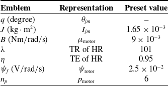
This paper employs numerical simulation to assess the efficacy of the robust elastic control strategy. Key parameters of the disc motor are detailed in Table I, which are then used to calculate Eq. (11), yielding the matrix in Eq. (15) that forms the basis for the simulation analysis.
In assessing the relative performance of PID, MPD, ADRC and FHPD in position tracking tasks, we utilized both step and sinusoidal inputs for our experiments, facilitating a comprehensive evaluation of the data obtained.
Constituents and variables of the joint module mechanism.

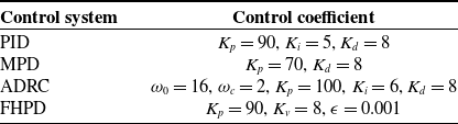
Variables within control strategies.

After thorough testing of the control parameters for three algorithms to ensure a fair comparison and to find a balance between system stability and response speed, we determined the optimal parameter settings as shown in Table II. In the simulation of the FHPD control strategy, the uncertainty introduced by the cosine function had a relatively minor impact on the disc motor.
Disc motor’s sine wave tracking simulation results.

Sinusoidal signal tracking.

However, when the motor was subjected to sinusoidal disturbances, the impact was significantly greater compared to square wave disturbances. Based on this finding, we decided to adopt the formula
 $\hat {F}= 0.5+0.01* \sin \left ( 5t\right )$
to represent the uncertainty factor of the motor. The initial error
 $e\left (\circ \right )$
was set to zero at the start of the experiment, and a fixed sampling interval of 0.001 s was chosen.
-
1. Step Response Test: The amplitude of the step signal, denoted as
${q}^{d}$
, is set to
$51.0556^{\circ }$
. The corresponding results are displayed in Figure 4. It was noted that the FHPD controller achieved the target trajectory more swiftly and without any overshoot, outperforming both the PID and MPD controllers. -
2. Sinusoidal Signal Tracking: The sinusoidal signal is considered as the reference path for tracking with amplitude
$80.6686^{\circ }$
.


Figures 5 presents the simulation results for a sinusoidal signal tracking scenario using a Stribeck friction model. The system’s initial response to the sinusoidal signal was similar to that of a step input scenario. Upon reaching a steady state, the FHPD controller demonstrated a reduction in steady-state error and a shorter time to recovery compared to the PID and MPD controllers, exhibiting a swifter return to stability. The findings from these simulations indicate that the discussed controller is effective in enhancing the system’s dynamic response capabilities.
The experimental platform known as CSPACE.

3.4. Experiment
A series of experiments focusing on the disc motor have been conducted to thoroughly verify the applicability of the control algorithm. As depicted in Figure 6, the experimental setup includes a computer, cSPACE supervisory software, a cSPACE control unit, and a disc motor embedded in a hip-assisting exoskeleton robot, among other equipment. An encoder with a 2500-line incremental count capability is utilized to collect positional data of the motor, with the simulation tests employing identical parameter settings.
The experimental procedure consists of three main stages: Firstly, the positional signals of the motor are acquired by the incremental encoder and fed back to the controller; Secondly, the digital signal processor within the cSPACE system, in accordance with our proposed control strategy, receives and processes the incoming data; Lastly, the motor is driven by augmenting the control signal, thereby achieving precise motion control of the disc motor.
-
1. Transient performance in the simulation experiments in Figure 7 illustrates the effect of the FHPD control strategy on the disc motor’s response to a step signal. The FHPD controller not only achieves rapid stabilization but also maintains high control precision, with errors being smaller and exhibiting superior convergence speed compared to other controllers.
-
2. Steady-state Performance, Figure 8, compares the performance of the three control strategies in the sinusoidal signal tracking experiment. Additionally, as can be seen from Figure 8, the FHPD control strategy outperforms PID and MPD in terms of accuracy, which is consistent with the simulation analysis. The highest tracking errors typically occur when the disc motor’s speed is near zero, mainly due to the imprecision of the position sensor and static friction. The experimental results indicate that there is almost no difference in control current among the three approaches.
Figure 9 presents a comparative analysis of current waveforms for the FHPD, MPD, and PID controllers during experimental operation. The results indicate that the FHPD controller achieves significantly reduced current oscillations compared to the other methods, demonstrating enhanced stability and energy efficiency. Notably, the FHPD exhibits lower peak currents and reduced fluctuations, which directly translate to decreased energy consumption. This improved performance is attributed to the FHPD’s optimized control strategy, which minimizes unnecessary power usage while maintaining precise tracking. The figure clearly illustrates the practical benefits of the FHPD controller in real-world applications.
The experiment results of step response analysis.

Sinusoidal response analysis.

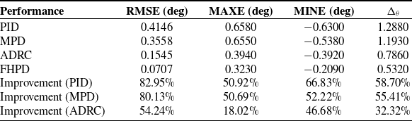
Table III presents a summary and comparison of the experimental findings. This comparison includes key performance indicators such as the root mean square error (RMSE), maximum error (MAXE), minimum error (MINE), and the range of error (
 $\Delta _{\theta }$
).
 \begin{equation} M A X E=\max \left (\left |\theta _{i}\right |\right ) \end{equation}
 \begin{equation} M I N E=\min \left (\left |\theta _{i}\right |\right ) \end{equation}
 \begin{equation} R M S E=\sqrt {\frac {1}{n} \sum _{i=1}^{n} \theta _{i}^{2}} \end{equation}
 \begin{equation} \Delta _{\theta }=\theta _{M A X E }-\theta _{M I N E } \end{equation}
Comparison of control response performance of different control methods.

Current waveform comparison.

The variable
 $ n$
indicates the total number of samples, while
 $ \theta _i$
signifies the tracking error for each individual sample
 $ i$
. The analysis indicates that the FHPD controller exhibits significant improvements in tracking accuracy and robustness compared to the PID, MPD, and ADRC methods. The FHPD controller demonstrates a substantial reduction in both RMSE and MAXE, along with a narrower error range, which underscores its enhanced performance and stability. These improvements are particularly important for maintaining consistent performance across various experimental conditions, highlighting the FHPD controller’s effectiveness in handling uncertainties such as tracking errors.
To comprehensively evaluate the performance of the FHPD controller against traditional PID and MPD controllers, we have incorporated several illustrative figures. The left figure in Figure 10 presents a bar chart comparing the tracking error range width from the sinusoidal tracking experiment, clearly highlighting the disparities in error ranges among the three methods. The results demonstrate that the proposed FHPD controller achieves a tracking error of
 $0.532^{\circ }$
, representing a 58.70% reduction compared to the traditional PID controller (
 $1.288^{\circ }$
) and a 55.41% reduction compared to the traditional MPD controller (
 $1.193^{\circ }$
). Additionally, the FHPD controller outperforms ADRC (
 $0.786^{\circ }$
) by reducing the tracking error by 32.32%. These findings highlight the superior performance of the FHPD controller in tracking accuracy. The right figure in Figure 11 offers a radar chart depicting the improvement percentages of the FHPD method relative to the others, visually emphasizing its significant performance enhancement. The left figure in Figure 11 displays a bar chart contrasting the stability difference width between simulation and experimental results in the step response test, demonstrating the FHPD controller’s consistent performance across both scenarios. The right figure in Figure 10 provides a bar chart of the difference percentages between simulation and experimental results for the three methods, further substantiating the reliability of the FHPD controller. Together, these visual aids effectively elucidate the performance variations among different control methods and underscore the superiority of the proposed FHPD controller.
4. Conclusion
This study proposes a fractional-order hybrid PD (FHPD) control framework that synergistically integrates mechanical dynamics modeling with adaptive robustness mechanisms. Lyapunov stability analysis formally guarantees the boundedness of system uncertainties and disturbances. Through comprehensive simulations and experimental validations under trajectory tracking tasks, the FHPD demonstrates 58.70% reductions in tracking error range compared to PID, respectively, significantly outperforming conventional methods in precision control. Notably, the experimental results maintain exceptional consistency with simulations, exhibiting less than 0.009% deviation in step response steady-states. These quantifiable improvements confirm the controller’s dual advantages in dynamic accuracy and implementation reliability. The proposed methodology provides a generalized solution for nonlinear systems with inherent uncertainties, particularly effective in load fluctuation mitigation. Future work will extend this architecture to multi-DOF robotic systems to explore its scalability in complex operational scenarios.
Tracking error and improvement analysis.

Simulation-experiment comparison.

Author contributions
Xiaoli Liu, Youli Hu and Faliang Wang conceived and designed the study. Shengchao Zhen conducted data gathering. Ye-Hwa Chen performed statistical analyses. Xiaoli Liu, Youli Hu and Faliang Wang wrote the article.
Funding statement
This work was supported in part by the National Natural Science Foundation of China (Grant No. 52305084 and 52175083); in part by the Natural Science Foundation of Anhui Province (Grant No.2308085QE161); in part by the Fundamental Research Funds for the Central Universities (JZ2024HGTG0300); in part by the University Synergy Innovation Program of Anhui Province (GXXT-2023-108); in part by the University-Local Government Collaborative Industry Innovation Guidance Fund Project (JZ2024YDZJ0038).
Competing interest
The authors declare no potential conflicts of interest with respect to the research, authorship, and/or publication of this article.
Ethical approval
None.