I. INTRODUCTION
A nanograined (NG) metal usually exhibits a higher tensile strength and a lower tensile ductility in comparison with its coarse-grained (CG) counterpart.Reference Fang, Li, Tao and Lu1 The enhancement of tensile strength can be attributed to the grain refinement, following the well-known Hall–Petch relationship.Reference Hall2,Reference Petch3 The increased brittleness may be attributed to two reasons. First is the reduced dislocation glide, which is effectively obstructed by the extremely small grains. Second is the lack of grain boundary sliding or diffusional creep to accommodate plastic deformation.Reference Fang, Li, Tao and Lu1 Nieman et al.Reference Koch4 reported that NG Cu prepared by the inert gas condensation method has an elongation of 8%. Karimpoor et al.Reference Karimpoor, Erb, Aust, Wang and Palumbo5 reported that nanocrystalline Co with a 12 nm average grain size has a tensile strength about 3 times that of CG Co while maintaining a 7% elongation in tension.
To expand the applications of nanocrystalline materials, an improved strength without much sacrifice in ductility is desired. Since a nanocrystalline metal is strong and brittle, while its CG counterpart is more ductile and less strong, an ideal design of a metal material is such that one side of the metal is NG and the other side is coarse grained, with the former providing a good global strength and the latter providing ductility. This design can be realized by either ex situ or in situ methods. The ex situ method involves growing a NG metal layer on a CG substrate by means of film deposition, including electrodeposition,Reference Zhou, Wang, Jia, Liu, Yang and Jiang6 magnetron sputtering,Reference Ye, Li and Wang7,Reference Wang, Wang, Liu, Gong and Song8 etc. On the other hand, the in situ method creates a nanostructured top layer by means of severe plastic deformation (SPD)Reference Kang and Kim9–Reference Yapici, Karaman, Luo, Maier and Chumlyakov12 on the surface of a CG metal. The main advantage of a sample treated by the in situ method is the absence of a shape interface between the nanostructured layer and the CG substrate, which may produce outstanding properties.
In this paper, a fast multiple rotation rolling (FMRR) technique was used to synthesis a nanostructured layer on the surface of a 316 stainless steel sample. The aim is to study the effect of nanostructured layer on tensile properties.
II. EXPERIMENTAL PROCEDURE
Used in this work is a 316L stainless steel plate. The as-received sample was annealed at 1173 K for 60 min to obtain a homogeneous CG microstructure, and then the sample was treated by FMRR. Based on the realization of SPD, the FMRR equipment used in this work is designed. Under a static pressure of P, an array of rotational tool tips can fast rotate and roll on a sample surface at a rotational speed of ω. The sample being treated moves steadily at a linear velocity of υ in one of the horizontal directions back and forth, thus a full surface treatment can be completed. The details of the FMRR process have been introduced in previous investigation.Reference Chui, Sun, Sun, Wu, Wang and Zhao13 In the present work, the processing parameters are as follows: P = 4.3 MPa (pressure), υ = 1.5 mm/s (horizontal velocity), ω = 1600 rpm (rotational speed), and t = 60 min (duration of FMRR).
The microstructure of the sample’s surface layer was characterized by transmission electron microscopy (TEM) on a JEOL JEM-2100, operating at a voltage of 200 kV. The TEM sample was obtained by several procedures: cutting, mechanical polishing, dimpling and ion thinning from one side. X-ray diffraction (XRD) analysis was performed with the Cu Kα radiation in a Rigaku D/max-2500 x-ray diffractometer at a 2θ scanning rate of 4 °/min to check the phase constituent in the surface layer. The cross-sectional morphology was observed by using an optical microscope (OM) of type EPIPHOT 300. Tensile tests were carried out on a CMT5150 Electromechanical Universal Testing Machine at room temperature. The dimensions of NCG (the NCG is an abbreviation of the name for such a structure, of which one side is an NG structure and the other side is a CG structure) and CG samples for tensile tests are 12 × 3 × 0.5 mm3, the dimensions of the NG sample are 12 × 3 × 0.08 mm3, and the strain rate is 7 × 10⁻⁴/s. A scanning electron microscope (SEM) of type JSM-6610LV was used to characterize the fracture surfaces of the samples after tensile tests.
III. RESULTS AND DISCUSSION
A. Microstructure analysis of the surface layer
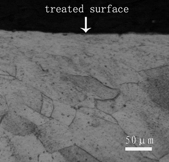
The cross-sectional OM micrograph of the FMRR sample was shown in Fig. 1. During FMRR treatment, those tool tips on the surface of the 316L stainless steel sample induce a plastic deformation layer with a thickness of about 80 μm. Evidence for SPD is clearly seen in the surface layer.
Cross-sectional OM observation of the FMRR sample.

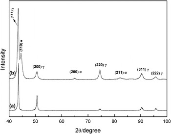
Figure 2 shows the XRD patterns of the original sample and the FMRR sample. It can be seen from Fig. 2(b) that besides the diffraction peaks of austenite (γ), the peaks of α-martensite exist in the FMRR sample. From Eq. (1) in the literature,Reference Fultz and Howe14 the volume fraction of martensite (V α) can be calculated as follows:
 $$V_{\rm{\alpha }} = 1 - {{0.65(I_{311{\rm{\gamma }}} + I_{220{\rm{\gamma }}} )} \over {I_{211{\rm{\alpha }}} + 0.65(I_{{\rm{311\gamma }}} + I_{220{\rm{\gamma }}} )}}\quad,$$
where I represents the integrate for the reflecting plane. Using the (211) reflection for α-martensite, V α was determined to be about 20% after FMRR treatment. Comparing Figs. 2(a) and 2(b), we can be clear that the full width at half maximum of diffraction peaks for the FMRR sample is much bigger than that for the original sample, which can be attributed to the grain refinement and microstrain. According to the Scherrer and Wilson equation,Reference Klug and Alexander15 the grain size in the surface layer of samples is calculated by use of an XRD Pattern Processing and Quantification Program referred as Jade 5 developed by MDI materials Data. Inc. The average grain size in the surface layer of the FMRR sample is determined to be 15 nm.
XRD patterns of the original sample and the FMRR sample.

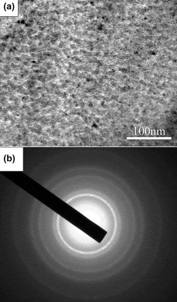
Figure 3 shows the typical TEM bright field image and the corresponding selected area electron diffraction (SAED) pattern for the top surface layer of the FMRR sample. Observations show that equiaxed nanograins with the average grain size of about 12 nm are obtained in the surface layer. The SAED pattern in Fig. 3(b) indicates further that the grains have been refined to the nanoscale level and the grains are random in crystallographic directions. For the FMRR sample, the grain size determined from the TEM observation is a litter smaller than that from the XRD calculation. This might be originated from the fact that XRD analysis averages the structural information of a surface layer of about 5 μm, while the TEM sample is a very thin film (<1 μm thick) at the sample surface.Reference Wang, Yu and Dong16
A TEM bright field image and an associated SAED pattern for the top surface layer of the FMRR sample.

B. Tensile properties
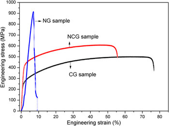
Engineering stress–strain curves of the NG, NCG (the NCG is an abbreviation of the name for such a structure of which one side is an NG structure and the other side is a CG structure) and CG samples are shown in Fig. 4. Obviously, the strength of the NG sample is much higher than that of the CG. The NG foil showed an ultimate tensile strength of ∼913 MPa, while elongation-to-failure for the nanostructured sample is only 9%. The ultimate tensile strength of the NCG sample reaches a higher value of about 608 MPa, which is increased by ∼22% compared with that of the CG sample (∼500 MPa). The yield strength (0.2% offset) is increased by 51% from 242 MPa for the CG sample to 365 MPa for the NCG one. On the other hand, elongation for the NCG sample is about 38%, while that for the CG sample is about 50%. The result indicates that plasticity is slightly reduced. Though the NG structured layer sample exhibits a much higher strength in comparison to the NCG sample, the plasticity is reduced for the NG sample. However, the NCG sample enhances mechanical properties of the 316L stainless steel without much sacrifice in its ductility.
Tensile engineering stress–strain curves for the samples.

The high strength of the 316L stainless steel is attributed to the grain size effect in terms of the Hall–Petch relationship.Reference Suryanarayana17 The yield strength can be expressed as a function of grain size as follows:
 $${\rm{\sigma }} = {\rm{\sigma }}_0 + K_h \cdot d^{ - 1{\rm{/2}}} \quad,$$
where σ is the 0.2% yield strength, σ0 is the lattice friction stress to move individual dislocations, d is the grain size, and K h is a constant, called the Hall–Petch intensity parameter. Obviously, the strength increases with a decrease in the grain size. From another point of view, nanocrystalline materials reduce the size of nucleating flaws and increase the resistance to crack propagation, leading to a higher fracture stress.Reference Wang, Chen, Zhou and Ma18,Reference Wang, Ma and Chen19 Accordingly, the nanostructured 316L stainless steel shows a much higher strength than the CG structure sample, and the thickness of the nanostructured layers is very small of the total sample thickness. In addition, FMRR treatment is based on the principle of SPD. Therefore, work-hardening was introduced in the process of SPD. At the same time, deformation-induced α-martensite was also produced. So, both of them have some contributions also in the improvement of strength. On the other hand, although the plasticity is slightly reduced in the NCG specimen, it reaches a higher value of about 38%. According to Chen et al.Reference Chen, Lu, Lu and Lu20 the plasticity of a nanocrystalline 316L stainless steel with an average grain size of about 40 nm is only about 3.4%. The plasticity was reduced because nanograins tend to lose the work-hardening on deformation owing to their very low dislocation storage efficiency inside a tiny grain. Such a material is prone to plastic instability, limiting the desirable uniform elongation.Reference Wang, Ma and Chen19 In general, nanograins are believed to be strong but often exhibit low tensile ductility.Reference Fang, Li, Tao and Lu1 However, the strength of the NCG 316L stainless steel treated by FMRR not only improved the plasticity but also is about ten times higher compared with that of a NG sample according to the investigation of Chen et al.Reference Chen, Lu, Lu and Lu20
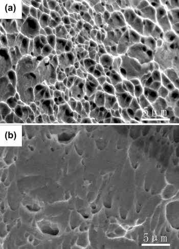
Figure 5 shows the structure of a fractured surface after tensile tests. Two kinds of different structures of the fracture are observed in the surface layer of the samples. Ruptures with numerous dimples were seen on the fracture surface of the CG matrix, implying a great deal of plastic deformation prior to failure.Reference Fang, Li, Tao and Lu1 On the contrary, the quantity of dimples was few on the fracture surface of the NG layer, which indicates the reduction of plastic strain.Reference Chen, Lu, Lu and Lu20
Fracture surface morphologies of the CG (a) and the NG (b) samples.

The strength of nanocrystalline metals is improved at the cost of their ductility.Reference Fang, Li, Tao and Lu1,Reference Gleiter21 In our study, the 316L stainless steel, which consists of an NG surface layer and a CG bulk, can markedly improve its strength without much sacrifice in ductility. This is because that the NG surface layer provides a good global strength and the CG bulk provides ductility. Hence, the FMRR technique provides an approach for enhancing mechanical properties of engineering materials. A widespread application of the FMRR technique is anticipated in practical engineering.
IV. CONCLUSION
A nanocrystalline layer on the surface of a 316L stainless steel plate was prepared by the FMRR technique. The yield strength (0.2% offset) of the NCG sample is increased by 51% compared with that of the CG sample. The strengthening of the NCG sample is mainly attributed to the NG microstructure of the surface layer. The plasticity was slightly reduced due to effective obstruction of the dislocation glide in the NG surface layer. Although plasticity decreases slightly, the elongation still reaches a high value of about 38%. Hence, the FMRR technique provides an approach for enhancing mechanical properties of engineering materials without much sacrifice in its ductility.
ACKNOWLEDGMENTS
This work was supported by the Natural Science Foundation of the People’s Republic of China (Grant Nos. 81171463 and 30800221), China Postdoctoral Science Foundation (Grant No. 200804401138), and Graduate Independent Innovation Foundation of Shandong University (Grant No. yzc11053).