1. Introduction
In the last decade, researches on various kinds of unmanned aerial vehicles (UAVs) have received much attention in the automatic control area [Reference Bae and Fahimi1, Reference Villanueva, Luque-Vega, González-Jiménez and Arellano-Muro2]. The UAVs have been widely used in different tasks such as surveillance, visual acquisition, exploration, and disaster assistance in urban circumstances [Reference Valavanis and Vachtsevanos3]. The ability to perform autonomous landing on a moving platform is a key feature for UAVs in the aerial transportation and logistics applications. For instance, a delivery system consists of multiple UAVs, and a truck is introduced in ref. [Reference Raj and Murray4]. The effectiveness of such kinds of logistics systems depends on minimizing travel distance and travel time [Reference Baniasadi, Foumani, Smith-Miles and Ejov5]. The autonomous landing maneuver effectively reduces traveling time and energy consumption per trip.
The autonomous landing problem is studied for different kinds of UAVs such as fixed-wing airplanes, helicopters, and also quadrotors. To the best of author’s knowledge, the early researches in the field of quadrotor’s autonomous landing on moving platform appeared around 2010 [Reference Voos and Bou-Ammar6, Reference Herisse, Hamel, Mahony and Russotto7]. Early works are concentrated on the problem formulation and giving simple possible solutions [Reference Daly, Ma and Waslander8, Reference Benavidez, Lambert, Jaimes and Jamshidi9]. While the real-world conditions and challenges are not considered in their work. At the initial stage of research, the challenge of vehicle localization is overcame by using global positioning system (GPS) like VICON [Reference Lee, Ryan and Kim10] or Opti-Track [Reference Daly, Ma and Waslander8] to obtain a ground-truth position for indoor experiments, while researches are focused on the control system design, only [Reference Lee, Ryan and Kim10]. The other challenges that are neglected frequently in the literature are actuator dynamics [Reference Serra, Cunha, Hamel, Cabecinhas and Silvestre11] and wind-induced disturbance forces [Reference Serra, Cunha, Hamel, Cabecinhas and Silvestre11–Reference Ghommam and Saad13]. Such kinds of challenges make the problem more complicated and severely affect the general performance of a control system. Sometimes, the ground vehicle communicates or cooperates with the quadrotor UAV in the autonomous landing maneuver, and the states of the ground vehicle from its internal sensors are available to the control system [Reference Daly, Ma and Waslander8]. For instance, in the outdoor experiment of Daly et al. [Reference Daly, Ma and Waslander8], the GPS and inertial measurement unit are used for vehicles’ localization while the performance of the control system is restricted by accuracy of GPS unit. High precision GPS units which are used in military applications are very expensive and usually unavailable. Consequently, in most outdoor experiments, commercial GPS units are only used in the long-range and a vision-based position estimation method is utilized to obtain local relative positions in the short range. Using a vision-based positioning system makes this possible to land autonomously on a moving platform without its cooperation. In this way, researchers focus on the development of vision positioning systems while conventional proportional-integral-derivative (PID) controllers are employed as vehicles’ motion controllers [Reference Wenzel, Masselli and Zell14, Reference Bi and Duan15]. For instance, Wenzel et al. [Reference Wenzel, Masselli and Zell14] have developed a pose estimation system using infrared technology which has some restrictions due to pattern size and angle of sight that works only in 2.5-m distance and is not suitable for outdoor experiments which is exposed to sun light. Bi and Duan [Reference Bi and Duan15] have introduced a visual tracking system for a quadrotor to find and track the position of red-green-blue-colored helipad in the image plane. The proposed method is also restricted by a limited detection range. The autonomous landing maneuver is a complex task. A successful autonomous landing needs more precise pose estimation method and more reliable motion controller for stabilization, tracking, and vertical landing maneuvers of quadrotor UAV despite the wind-induced disturbance force. Visual pose estimation methods have been used in several studies as a low-cost and efficient method for landing air vehicles on a moving target. Kim et al. use a simple color pattern and blob detection analysis for the purpose of landing [Reference Kim, Jung, Lee and Shim16]. In another study, a visual marker made of concentric rings is used on the landing pattern [Reference Lange, Sunderhauf and Protzel17]. In another study, researchers use a visual fiducial named ArUco [Reference Yang, Ying, Lu and Li18]. Olson et al. introduced AprilTag as a robust and flexible visual fiducial system [Reference Olson19]. Since then, AprilTag has been used in several kinds of research for pose estimation proposes [Reference Borowczyk, Nguyen, Phu-Van Nguyen, Nguyen, Saussié and Le Ny20, Reference Wang, She and Si21]. In recent years, researchers have focused on the time optimal solutions in the vision-based control systems to perform autonomous landing maneuver in the possible minimum time [Reference Almeshal and Alenezi22]. They work around the optimal path generation for autonomous landing maneuver while the conventional PID controller is widely used as a quadrotor motion controller [Reference Hu and Mishra23, Reference Rodriguez-Ramos, Sampedro, Bavle, De La Puente and Campoy24]. Unfortunately, the effects of wind-induced disturbance forces and actuator dynamics are not studied in these works. There are a few kinds of research in this area that represents a complete solution for autonomous landing problem and takes into the account the real-world challenges [Reference Qi, Jiang, Wu, Wang, Wang and Shan25, Reference Bhargavapuri, Shastry, Sinha, Sahoo and Kothari26]. In general, optimal path generation should make the autonomous landing maneuver faster [Reference Heidari and Saska27]. But, in our opinion, development of a fast and robust motion controller for quadrotor system can make critical improvements on landing time and precision in the real-world experiments that wind-induced disturbance forces are unavoidable. In most of the previous works, the proposed control method is employed for position control of quadrotor and the attitude control realized by using conventional PID controller. There is a known tradeoff between fast and robust response to be obtained by conventional PID controller. Consequently, a conventional PID controller usually is not fast or robust enough for a nonlinear under-actuated quadrotor system to perform complicated tasks such as autonomous landing on a moving platform in the presence of wind disturbance. In some researches, the problem is simplified by neglecting the actuator dynamics and wind induced disturbance force in the simulations. In addition, the proposed vision positioning systems in the literature are restricted by detection range and accuracy [Reference Polvara, Sharma, Wan, Manning and Sutton28]. The most utilized vision positioning methods are image-based visual servo (IBVS) and position-based visual servo (PBVS). The IBVS method relies on the target location in the image frame coordinates and does not consider the relative height. Consequently, it may cause undesirable interactions at the moment of touchdown since there is no information to slow down quadrotor UAV during vertical landing. The PBVS method provides more useful information for the control system since the relative height is also estimated. However, the performance of the PBVS method relies on the target size and geometry. There is a known challenge in the literature to estimate relative position precisely both in short and long ranges with the PBVS method. Large fiducial markers are suitable for long range while they cannot be detected in short range since they cannot fit in the camera frame. Inevitably, it imposes long free falls at the end of a vertical landing phase because of losing position feedback. Obviously, small fiducial markers cannot be detected from far distances and cannot be applied for approaching phase. Performance of the vision positioning method needs to be improved both in precision and detection range. On the other hand, it seems it is necessary to have a fast and more robust controller for nonlinear under-actuated system of quadrotor to perform autonomous landing maneuver despite wind induced disturbance force. Simultaneously, the controller needs to be feasible for onboard implementation and tuning.
This paper aims at the design of a closed-loop vision-based control system for quadrotor UAV to perform autonomous landing maneuver in the possible minimum time despite the wind-induced disturbance force. It is assumed that the unmanned ground vehicle (UGV) moves independently, and there is no communication and collaboration between two vehicles. An onboard vision positioning system is utilized to obtain the relative position of the moving landing pad. A compound fiducial marker is introduced as the target of the vision positioning system which enables high precision relative positioning in the range between 10 and 350 cm height. High precision positioning of the compound fiducial marker provides opportunity of safe and precise touchdown and eliminates risk of long free falls at the last step of vertical landings. The major contributions of this paper are as follows:
-
• A fractional-order fuzzy proportional-integral-derivative (FOFPID) controller is introduced for the nonlinear under-actuated system of quadrotor.
-
• The actuator dynamics is included to simulate more realistic model of quadrotor and make a challenge with transient response and saturated output thrust of actuators.
-
• A supervisory control algorithm is proposed as autonomous landing path generator to perform fast, smooth, and accurate landings.
The proposed FOFPID controller is an efficient integration of fuzzy logic and fractional-order calculus into the PID control hypothesis. Fuzzy systems usually provide fast and overshoot-less responses, while fractional-order systems give higher stability and robustness. The integration makes this possible to benefit from the advantages of both systems at the same time. The proposed FOFPID controller holds the simplicity of a conventional PID controller and is easy for onboard implementation. Also, it has more degree of freedom (DOF) for tuning. The proposed FOFPID controller along with feedback linearization method provides fast and more robust response for the nonlinear under-actuated system of quadrotor which cannot be achieved by a conventional PID controller.
Performance of the proposed FOFPID controller is obtained in multiple software-in-the-loop (SITL) simulations and is compared with fuzzy PID (FPID), fractional-order PID (FOPID), and conventional PID controllers. Simulation results reveal the superior performance of the proposed FOFPID controller over the other ones in terms of landing time and landing accuracy indexes.
The rest of this paper is organized as follows: Section 2 briefly represents the mathematical model of a quadrotor and its electrical actuators. Section 3 contains an overall description of the quadrotor control system, detailed representation of the proposed control methods, and demonstration of the vision positioning system. Simulation setup and simulation results are demonstrated in Section 4. Conclusion is discussed in Section 5.
2. Quadrotor model
Quadrotor is the most popular kind of multi-rotor UAVs due to its simple mechanics and high maneuverability (e.g., vertical takeoff and landing, stationary flight, etc.). Quadrotor’s mechanical structure consists of a symmetric cross-shaped rigid body and four electrical rotors which are located at the end of cross arms. Schematic model of a quadrotor is depicted in Fig. 1. It is assumed that the center of gravity of the quadrotor is located at the intersection point of the cross arms, and the quadrotor has a diagonal inertia tensor about its principal axes. Hereafter, the variables
 $m$
,
 $L$
, and
 $I = diag\left( {\left[ {{I_{xx}},{I_{yy}},{I_{zz}}} \right]} \right)$
are the quadrotor’s mass, the arm’s length, and the quadrotor’s inertia tensor, respectively.
Schematic model of a quadrotor.

2.1. Body dynamics
Two coordinate systems are introduced in Fig. 1 for dynamical analysis of the quadrotor’s body: the first is the earth-fixed inertial frame defined by
 $\left\{ E \right\}\,:\,\{ {\vec O,( {\hat X,\hat Y,\hat Z} )} \}$
, and the second is the body-fixed frame defined by
 $\left\{ B \right\}\,:\,\{ {\vec P,( {\hat x,\hat y,\hat z} )} \}$
. Vector
 $\vec O = {\left[ {0,0,0} \right]^T}$
indicates the origin of the earth-fixed inertial frame
 $\left\{ E \right\}$
. Also, vector
 $\vec P = {\left[ {X,Y,Z} \right]^T}$
indicates the origin of the frame
 $\left\{ B \right\}$
in the earth-fixed inertial frame
 $\left\{ E \right\}$
. Orientation of the body-fixed frame
 $\left\{ B \right\}$
with respect to the frame is defined by roll–pitch–yaw angles which are denoted by
 $\phi ,\theta $
, and
 $\psi $
, respectively. The quadrotor translational dynamics is obtained in the inertial frame
 $\left\{ E \right\}$
, while its rotational dynamics is obtained in the body frame
 $\left\{ B \right\}$
.
The thrust force (
 ${T_i}$
) and the aerodynamic torque (
 ${Q_i}$
) are produced by the four propeller spinning rotors which are given by Eqs. (1) and (2), respectively [Reference Kayacan and Maslim29]:
 \begin{align}{T_i} = b{\omega _i}^2 \qquad \quad i = 1, \cdots ,4\end{align}
 \begin{align}{Q_i} = d{\omega _i}^2\qquad \quad i = 1, \cdots ,4\end{align}
where
 ${\omega _i}$
,
 $b$
, and
 $d$
are angular speed of the i-th rotor, thrust factor, and drag factor, respectively. According to Eqs. (3)–(6), combination of the thrust forces and the aerodynamic torques produce four generalized forces in the body frame
 $\left\{ B \right\}$
[Reference Kayacan and Maslim29]:
 \begin{align}{U_1} = \mathop \sum \limits_{i = 1}^4 {T_i} = b\left( {\omega _1^2 + \omega _2^2 + \omega _3^2 + \omega _4^2} \right)\end{align}
 \begin{align}{U_2} = {T_4}L - {T_2}L = Lb\left( {\omega _4^2 - \omega _2^2} \right)\end{align}
 \begin{align}{U_3} = {T_3}L - {T_1}L = Lb\left( {\omega _3^2 - \omega _1^2} \right)\end{align}
 \begin{align}{U_4} = \mathop \sum \limits_{i = 1}^4 {\left( { - 1} \right)^{i + 1}}{Q_i} = d\left( {\omega _1^2 - \omega _2^2 + \omega _3^2 - \omega _4^2} \right),\end{align}
where
 ${U_1}$
is the actuation force along
 $\hat z$
axis,
 ${U_2}$
is the actuation torque about
 $\hat x$
axis,
 ${U_3}$
is the actuation torque about
 $\hat y$
axis, and
 ${U_4}$
is the actuation torque about
 $\hat z$
axis. Quadrotor’s rotational dynamics is represented in Eq. (7) which is obtained using Euler’s rotational motion equations [Reference Kayacan and Maslim29]:
 \begin{align}\left[\begin{array}{c} {\ddot \phi } \\[6pt] {\ddot \theta } \\[4pt] {\ddot \psi } \end{array}\right] = \left[\begin{array}{c} \dfrac{{U_2} - {J_r}\dot \theta {\omega _r} + \left( {{I_{yy}} - {I_{zz}}} \right)\dot \psi \dot \theta }{{I_{xx}}}\\[13pt] \dfrac{{U_3} + {J_r}\dot \phi {\omega _r} + \left( {{I_{zz}} - {I_{xx}}} \right)\dot \psi \dot \phi }{{I_{yy}}}\\[13pt] \dfrac{{U_4} + \left( {{I_{xx}} - {I_{yy}}} \right)\dot \theta \dot \phi }{{I_{zz}}}\end{array}\right],\end{align}
where
 ${J_r}$
is the rotor moment of inertia and
 ${\omega _r}$
is the overall speed of rotors which is given by Eq. (8).
 \begin{align}{\omega _r} = - {\omega _1} + {\omega _2} - {\omega _3} + {\omega _4}.\end{align}
The translational dynamics of quadrotor is given from Newton approach [Reference Qi, Jiang, Wu, Wang, Wang and Shan25]:
 \begin{align}\left[\begin{array}{c} {\ddot X}\\[4pt] {\ddot Y}\\[4pt] {\ddot Z}\end{array}\right] = \left[\begin{array}{c}\dfrac{\left( {{C_\phi }{S_\theta }{C_\psi } + {S_\phi }{S_\psi }} \right){U_1}}{m}\\[13pt]\dfrac{\left( {{C_\phi }{S_\theta }{S_\psi } - {S_\phi }{C_\psi }} \right){U_1}}{m}\\[13pt]\dfrac{\left( {{C_\phi }{C_\theta }} \right){U_1}}{m} - g \end{array}\right],\end{align}
where
 ${S_.}$
and
 ${C_.}$
denote
 ${\rm{sin}}\left(\cdot \right)$
and
 ${\rm{cos}}\left( \cdot \right)$
functions, respectively. Also, the parameter
 $g = 9.81{\rm{m}}/{{\rm{s}}^2}$
is the gravity acceleration in the
 $\hat Z$
direction. Note that effect of aerodynamic torques on the translational motion and external disturbances are neglected. According to Eqs. (7) and (9), the quadrotor is an under-actuated system because it has six DOF but only four actual inputs. As a result, only four DOFs can be controlled independently (i.e.,
 $Z,\psi $
, and one from each pairs of
 $\left\{ {X,\theta } \right\}$
,
 $\left\{ {Y,\phi } \right\}$
). In this research, these four DOFs
 $\left\{ {X,Y,Z,\psi } \right\}$
are considered to be controlled independently.
2.2. Actuator dynamics
In this study, quadrotor actuators are considered to be brushed direct current (DC) electrical motors without speed reduction gears. Assuming that motor inductance has negligible effect, an approximated first-order equation can be obtained for actuator dynamics:
 \begin{align}{\dot \omega _m} = - \frac{d}{{{J_r}}}\omega _m^2 - \frac{{{K_{tm}}{K_{em}}}}{{{R_m}{J_r}}}{\omega _m} + \frac{{{K_{tm}}}}{{{R_m}{J_r}}}{V_a},\end{align}
where,
 ${\omega _m}$
is angular speed of rotor,
 ${V_a}$
is supply voltage of motor,
 ${K_{tm}}$
is motor torque constant,
 ${K_{em}}$
is electrical constant of motor,
 ${R_m}$
is motor resistance,
 ${J_r}$
is rotor inertia, and
 $d$
is drag factor. Electrical DC motors have a limited input voltage and generate a limited output torque/speed. Consequently, they generate a saturated thrust output which affects motion control of quadrotor in the presence of external disturbances. On the other hand, transient dynamic response of DC motors is very important when control system generates fast and high amplitude speed commands. The input voltage and output velocity limits are included using saturation function in the actuator dynamics.
In general, the actuator dynamics is included to simulate more realistic model of quadrotor. Indeed, it is included to make a challenge with transient response and saturated output thrust of actuators. While it is not considered in the control design, controllers are tuned with the limitations to obtain best possible fast and robust response. This is to ensure that stability and tracking performance are realized with reasonable available power of the actuators.
Architecture of the proposed control system.

3. Quadrotor control
Motion control of quadrotor is a challenging problem due to its nonlinear under-actuated dynamics [Reference Raj and Murray4]. Specially, controlling lateral motion of the quadrotor is the main problem since it is associated with under-actuated subsystem of the quadrotor dynamics [Reference Baniasadi, Foumani, Smith-Miles and Ejov5]. Although the quadrotor has under-actuated dynamics, it needs six controllers to track four desired trajectories and regulate roll and pitch angles simultaneously. Actually, roll and pitch dynamics are the internal dynamics for lateral motion of the quadrotor. Therefore, two single closed-loop control systems are employed to control quadrotor’s altitude and yaw maneuver, and an inner–outer-loop control paradigm is applied to control lateral motion of the quadrotor. The outer loop generates desired forces to control lateral translations of the quadrotor, while the inner loop controls roll and pitch maneuvers. Consequently, analytical inversion is needed to generate desired roll and pitch angles from desired lateral forces. Desired roll and pitch angles (
 ${\phi _d}$
and
 ${\theta _d}$
) can be obtained as follows [Reference Parivash and Ghasemi30]:
 $\begin{align}\left\{\begin{array}{c}{U_y^d = \left( {{C_{{\phi _d}}}{S_{{\theta _d}}}{S_\psi } - {S_{{\phi _d}}}{C_\psi }} \right)U_1^d}\\[9pt] {U_x^d = \left( {{C_{{\phi _d}}}{S_{{\theta _d}}}{C_\psi } + {S_{{\phi _d}}}{S_\psi }} \right)U_1^d}\end{array}\right\} \Rightarrow \left[\begin{array}{c@{\quad}c} {{S_\psi }} & { - {C_\psi }}\\[6pt] {{C_\psi }} & {{S_\psi }}\end{array}\right] \left[ \begin{array}{c} {{C_{{\phi _d}}}{S_{{\theta _d}}}}\\[4pt] {{S_{{\phi _d}}}}\end{array} \right] = \left[ \begin{array}{c} {{\dfrac{U_y^d}{U_1^d}}}\\[12pt] {{\dfrac{U_x^d}{U_1^d}}}\end{array}\right] \nonumber\\[8pt] \Rightarrow \left[\begin{array}{c}{{C_{{\phi _d}}}{S_{{\theta _d}}}} \\[4pt] {{S_{{\phi _d}}}} \end{array}\right] = \left[ \begin{array}{c}{{\dfrac{{S_\psi }U_y^d + {C_\psi }U_x^d}{U_1^d}}}\\[11pt] {{\dfrac{ - {C_\psi }U_y^d + {S_\psi }U_x^d}{U_1^d}}} \end{array}\right] \Rightarrow \left\{\begin{array}{c} {{\phi _d}} \\[4pt] {{\theta _d}}\end{array}\right\} = \left[\begin{array}{c} \textrm{arcsin} \left( \dfrac{ - {C_\psi }U_y^d + {S_\psi }U_x^d}{U_{1}^d} \right)\\[11pt] \textrm{arcsin} \left( \dfrac{{S_\psi }U_y^d + {C_\psi }U_x^d}{{C_{{\phi _d}}}U_{1}^d} \right)\end{array}\right], \end{align} $
where
 $U_x^d$
,
 $U_y^d$
, and
 $U_1^d$
are desired forces along
 $\hat X$
,
 $\hat Y$
, and
 $\hat z$
directions, respectively. Note, the saturation function is applied to keep the argument of the sine inverse function in the range between [−1 and 1].
3.1. Control system architecture
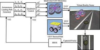
Architecture of the proposed vision-based closed-loop control system for autonomous landing maneuver of the quadrotor is depicted in Fig. 2. In the presented closed-loop control system, a vision positioning system computes the relative position of the compound AprilTag using the acquired image from virtual reality scene. Relative position is used as the only feedback source for the position controller subsystem and also as an input to the autonomous landing path generator subsystem.
The autonomous landing path generator is a supervisory control algorithm that is realized by a programmed state machine and manages the process of autonomous landing maneuver by simply generating conditional set points.
The quadrotor control subsystem gets relative position feedback and desired set points and generates motors speed commands using the proposed control law. Equations (7) and (9) can be expressed in the closed form of Eq. (12):
 \begin{align}\dot X = f\!\left( X \right) + b\!\left( X \right)U + D,\end{align}
with the state vector
 $X = \left[ {x,y,z,\phi ,\theta ,\psi } \right]$
and the disturbance vector
 $D$
, the control law is presented in Eq. (13):
 \begin{align}U_i^d = \frac{1}{{{b_i}\left( x \right)}}\left( {{\nu _\cdot } - {f_i}\left( x \right)} \right),\end{align}
where a simple feedback linearization term is considered to compensate model nonlinearities and an error dependent term (
 ${\nu.}$
) is included to achieve reliable tracking accuracy. It should be noted that the error dependent term
 ${\nu _\cdot }$
is the main part of the proposed control law and then is designed as the proposed FOFPID controller. Subsequently, the position and attitude control can be obtained by using the following control laws:
 \begin{align}U_y^d & = F{L_y} + m{\nu _y};\qquad\qquad {F{l_y} = 0}\nonumber\\[5pt] U_x^d & = F{L_x} + m{\nu _x}; \qquad\qquad {F{l_x} = 0}\\[5pt] U_1^d & = F{L_z} + {m \over {{C_\phi }{C_\theta }}}{\nu _z};\qquad {F{l_z} = {m \over {{C_\phi }{C_\theta }}}g}\nonumber \end{align}
 \begin{align}U_2^d & = F{L_\phi } + {I_{xx}}{\nu _\phi };\qquad {F{l_\phi } = \left( {{I_{zz}} - {I_{yy}}} \right)\dot \psi \dot \theta + {J_r}\dot \theta {\omega _r}}\nonumber\\[6pt] U_3^d & = F{L_\theta } + {I_{yy}}{\nu _\theta };\qquad {F{L_\theta } = \left( {{I_{xx}} - {I_{zz}}} \right)\dot \psi \dot \theta - {J_r}\dot \phi {\omega _r},} \\[6pt] U_4^d & = F{L_\psi } + {I_{zz}}{\nu _\psi };\qquad {F{l_\psi } = ({I_{yy}} - {I_{xx}})\dot \theta \dot \phi }\nonumber \end{align}
where
 $U_.^d$
is desired generalized force acting on the axis (.),
 $F{L_.}$
consist feedback linearization part of the control law, and term
 ${\nu.}$
denotes error dependent part of the control law. Finally, from desired generalized forces, velocity commands of the rotors are given by
 \begin{align}\left[ \begin{array}{c}{\omega _1^2}\\[5pt]{\omega _2^2}\\[5pt]{\omega _3^2}\\[5pt]{\omega _4^2}\end{array}\right] = \left[ \begin{array}{c@{\quad}c@{\quad}c@{\quad}c}b & b & b& b\\[4pt]0 & { - Lb} & 0& {Lb}\\[4pt]{ - Lb}& 0 & {Lb}& 0\\[4pt]d& { - d} & d& { - d}\\[4pt]\end{array} \right]^{ - 1}\left[ \begin{array}{c}{U_1^d}\\[5pt]{U_2^d}\\[5pt]{U_3^d}\\[5pt]{U_4^d}\end{array}\right].\end{align}
3.2. FOFPID controller
Structure of the proposed FOFPID controller is shown in Fig. 3. The proposed FOFPID controller is formed as fuzzy fractional-order PI + fuzzy fractional-order PD subsystem with a common core of fuzzy logic controller.
The fuzzy logic controller is a Mamdani-type fuzzy system with two scaled inputs (i.e., scaled tracking error and its scaled fractional-order derivative (
 $E,\dot E$
)). The Caputo fractional-order derivative is presented in Eq. (17):
 \begin{align}{}_0^CD_t^\mu U\left( t \right) = \frac{1}{{{\rm{\Gamma }}\left( {a - \mu } \right)}}\mathop \smallint \limits_0^t {\left( {t - \tau } \right)^{a - \mu - 1}}{U^{\left( a \right)}}\left( \tau \right)d\tau ,\end{align}
where,
 $\mu $
is the order of derivative,
 $a$
is integer supremum or least upper bound of
 $\mu $
(
 $a - 1 \lt \mu \lt a$
), and
 $U( t )$
is a continuous time-variant function. The Gamma function is denoted by
 ${{\Gamma }}({.})$
. Seven fuzzy sets with Gaussian membership function of Eq. (18) are considered for the fuzzy inputs and the fuzzy output in the range between
 $\left[ { - 1\ {\rm{and}}\ 1} \right]$
.
 \begin{align}\mu\! \left( x \right) = {e^{\frac{{ - {{\left( {x - c} \right)}^2}}}{{2{\sigma ^2}}}}}.\end{align}
The membership functions are depicted in Fig. 4. The proposed fuzzy rule base consists of 49 rules, and it is demonstrated in Table I. The fuzzy rule base is generally obtained by try and error in our previous work [Reference Parivash and Ghasemi30]. In the manual tuning procedure, fuzzy rule base is somehow rearranged to obtain smooth and homolographic surface for the fuzzy system output while counteracting the error growth. Abbreviations NL, NM, NS, Z, PS, PM, and PL mean negative large, negative medium, negative small, zero, positive small, positive medium, and positive large, respectively.
Fuzzy rule base.

Structure of the proposed fuzzy FOPID controller.

Membership function of fuzzy input–output.

Every rule is expressed in the form of Eq. (19), and the output rule firing strength is obtained by using Eq. (20). Kindly, see ref. [Reference Gottwald31] for more detailed descriptions on the fuzzy sets and fuzzy functions.
 \begin{align}{\rm{If}}\,E\,{\rm{is\ NL}}\,{\rm{And}}\,\dot E\,{\rm{is}}\,{\rm{NL}}\,{\rm{Then}}\,{U_{FLC}}\,{\rm{is}}\,{\rm{NL}}\end{align}
 \begin{align}{\mu _{N{L_E} \cap N{L_{\dot E}}}} = {\rm{min}}\left( {{\mu _{NL}}\left( E \right),{\mu _{NL}}\left( {\dot E} \right)} \right).\end{align}
In the proposed fuzzy logic controller, Mamdani min–max method is considered for inference engine. Consequently, a rule output and interfered output of the whole rules can be obtained by Eqs. (21) and (22), respectively. Kindly, see ref. [Reference Niemiec32] for more detailed descriptions on the Mamdani min–max inference method.
 \begin{align}\mu _{N{L^{'}}}^k\left( {{U_{FLC}}} \right) = {\rm{min}}\left({\mu _{N{L_E} \cap N{L_{\dot{E}}}}},{\mu _{NL}}\left( {{U_{FLC}}} \right) \right)\end{align}
 \begin{align}{\mu _{FLC}}\left( {{U_{FLC}}} \right) = \max \left\{ {\mu _\cdot ^1, \cdots ,\mu _{N{L^{'}}}^k, \cdots ,\mu _{\cdot}^N} \right\}k = 1, \cdots N.\end{align}
The centroid method is used for defuzzification to obtain the fuzzy system output (
 ${U_{FLC}}$
) according to Eq. (23).
 \begin{align}{U_{FLC}} = \frac{{\mathop \smallint \nolimits_U^{} y \cdot {\mu _{FLC}}\left( y \right)dy}}{{\mathop \smallint \nolimits_U^{} {\mu _{FLC}}\left( y \right)dy}}.\end{align}
Finally, output of the proposed fuzzy FOPID controller is given by
 \begin{align}{\nu _ \cdot } = \alpha {\rm{U}} + \beta D_{0,t}^{ - \lambda }\left( U \right),\end{align}
where
 $D_{0,t}^{ - \lambda }\left( U \right)$
denotes a fractional-order integration which is defined in Eq. (25).
 \begin{align}D_{0,t}^{ - \lambda }U\!\left( t \right) = \frac{1}{{{{\Gamma }}\!\left( \lambda \right)}}\mathop \int \limits_0^t {\left( {t - \tau } \right)^{\lambda - 1}}U\!\left( \tau \right)d\tau .\end{align}
There are six variables for tuning of the proposed FOFPID controller: variables
 ${K_e}$
and
 ${K_d}$
are the scaling factors of the tracking error (
 ${e_\cdot}$
) and its fractional-order derivative (
 ${}_0^CD_t^\mu e$
), respectively. Also, variables
 $\alpha $
and
 $\beta $
are proportional and integral gains, respectively. Coefficients
 $\mu $
and
 $\lambda $
are derivative and integration fractional order, respectively. Kindly, see refs. [Reference Parivash and Ghasemi33] and [Reference Sharma, Rana and Kumar34] for general stability analysis of the proposed FOFPID formulation.
In this research, it is assumed that The UGV move independently, and there is no communication and collaboration between two vehicles. Consequently, the onboard vision positioning system is the only available feedback source for position control subsystem and supervisory control algorithm.
3.3. Vision positioning system
Vision positioning systems are utilized to obtain the precise position and orientation of a desired object. For this purpose, a certain pattern is placed on the desired object as the target of vision positioning system. To simplify the detection, recognition, and tracking of moving object, the pattern can be a simple color pattern or a complex one. Using the camera parameters and patterns geometry, the pose of the camera with respect to the center of the pattern can be estimated. Pose estimation methods are critically dependent on the accuracy of camera calibration and object geometry [Reference Corke35].
In this paper, the PBVS method is employed for visual position estimation of the landing pad. A compound fiducial marker is introduced to be used as the target of PBVS method. The proposed compound fiducial marker is made of two concentric AprilTag fiducial markers as shown in Fig. 5.
AprilTag fiducial markers.

As shown in Fig. 5(c), the compound AprilTag consists of a large tag and a small tag which are shown separately in Fig. 5(a) and 5(b), respectively. The large AprilTag with a size of 50 × 50 cm is used for detection in far distances, and the small AprilTag with a size of 3 × 3 cm tag is used for near distances and high-precision landing. The small AprilTag, because of its small size, does not distort the overall pattern of the large AprilTag. The proposed compound fiducial marker enables high precision relative positioning of the landing pad using the PBVS method in the range between 10 and 350 cm height. It should be noted that the upper range can be extended easily by using a bigger large AprilTag.
The lower range is very important for autonomous landing maneuver since it implies minimum detectable relative height. Autonomous landing controller has to turn off the engines for a free fall and hopes a successful landing when reaches the minimum detectable relative height. There is a high risk for long free falls during vertical landing since it implies undesirable interaction forces with landing pad or the ground for unsuccessful landings (land outside of the landing pad). Also, long free fall cause inaccurate landing since the landing pad is moving by ground vehicle.
Using the proposed compound fiducial marker with PBVS method provides suitable detection ranges that eliminates the risk of free falls and can be employed by a supervisory landing controller to perform fast, smooth, and accurate landings.
3.4. Supervisory control algorithm
The supervisory control algorithm motivates the quadrotor UAV in the autonomous landing maneuver according to a mission scenario. The proposed supervisory control algorithm is depicted in Fig. 6. In the mission scenario, the quadrotor takes off from the landing pad surface and goes to 3 (m) height and hovers for 5 s. UGV starts moving within these 5 s and goes on an elliptic trajectory defined in Eq. (26).
 \begin{align} X\!\left( t \right) & = \left\{\begin{array}{c@{\quad}c} 0 & {0 \le t \le 20}\\[6pt] {2\cos \left( {\dfrac{\pi}{{30}}t - \dfrac{\pi}{2}} \right)} & {20 \lt t}\end{array}\right. \nonumber\\[8pt] Y\!\left(t\right) & = \left\{\begin{array}{c@{\quad}c} 0 & {0 \le t \le 20} \\[6pt] {1 + \sin \left( {\dfrac{\pi}{{30}}t - \dfrac{\pi}{2}} \right)} & {20{\rm{ }} \lt t} \end{array}\right. . \end{align}
Then quadrotor starts following ground vehicle and tries to achieve rendezvous conditions of Eq. (27):
 \begin{align}{\mathbb{C}_R} = \left\{\begin{array}{lc}\mathrm{Case}1:\,\mathrm{if}\left\{\begin{array}{c} \left| {{r_x}} \right| \le 0.2\\[3pt] {|{r_y}| \le 0.2}\\[3pt] {|{{\dot{r}}_x}| \le 0.2}\\[3pt] {|{{\dot{r}}_y}| \le 0.2}\\[3pt] {{r_z} \ge 0.5} \end{array}\right. & {\mathrm{Then}\ {Z_d} = {R_z} - 0.10}\\[40pt] \mathrm{Case}2:\,\mathrm{if} \left\{\begin{array}{c}\left| {{r_x}} \right| \le 0.15\\[3pt] {|{r_y}| \le 0.15}\\[3pt] {|{{\dot{r}}_x}| \le 0.15}\\[3pt] {|{{\dot{r}}_y}| \le 0.15}\\[3pt] {0.32 \lt {r_z} \lt 0.5} \end{array}\right. & {\mathrm{Then}\ {Z_d} = {R_z} - 0.01}\\[40pt] \mathrm{Case}3:\,\mathrm{if} \left\{\begin{array}{c} \left| {{r_x}} \right| \le 0.15\\[3pt] {\left| {{r_y}} \right| \le 0.15}\\[3pt] {\left| {{{\dot{r}}_x}} \right| \le 0.15}\\[3pt] {\left| {{{\dot{r}}_y}} \right| \le 0.15}\\[3pt] {{r_z} \le 0.5}\end{array}\right. & {\mathrm{Then}\ {Z_d} = 0.25\ (m)} \end{array}\right.,\end{align}
where,
 ${r_x}$
,
 ${r_y}$
, and
 ${r_z}$
are relative positions obtained from the vision positioning system along X, Y, and Z axes, respectively. Rendezvous conditions are defined on the relative position and velocity states. Whenever rendezvous conditions are satisfied, quadrotor starts vertical landing while tries to preserve rendezvous conditions. If rendezvous conditions are lost, the quadrotor preserves its height and tries to achieve rendezvous condition again. Rendezvous margins and vertical decent rate are decreased going step by step for smooth and accurate landings. When the quadrotor reaches the landing conditions of Eq. (28), supervisory controller commands turn off engines for a vertical touchdown. It should be noted that the final set point for relative height should be considered according to landing gear height for a smooth touchdown.
 \begin{align}{\mathbb{C}_L} = {\rm{If}}\left\{\begin{array}{l}\left| {{r_x}} \right| \lt 0.15\ (m)\\[6pt]{\left| {{r_y}} \right| \lt 0.15\ (m)}\ {\rm{Then}}\,{\rm{Turn}}\,{\rm{off}}\,{\rm{engines}}.\\[6pt]{{r_z} \le 0.3\ (m)} \end{array}\right.\end{align}
Proposed supervisory control algorithm.

4. Simulation results
An SITL simulation testbed is realized on the windows platform which integrates MATLAB/Simulink, Virtual reality, and Opencv softwares to simulate the proposed closed-loop control system. ViSP [Reference Marchand, Spindler and Chaumette36] is a modular cross-platform library and is based on open-source libraries including OpenCV which is used to detect and estimate position of the compound AprilTag. Numerical simulations are carried out on the windows platform on a personal computer with Intel core i7-5600 CPU and 16GB of RAM.
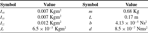
Main parameters associated with the quadrotor model are given in Table II Also, manually tuned gains for the proposed controllers are reported in Table III. The tuning procedure involves several numerical simulations of different set-point regulation and trajectory tracking tasks where the controller gains are tuned accordingly toward the best possible tracking and disturbance rejection performance.
Numerical parameters of the quadrotor model [Reference Kayacan and Maslim29].

Controller gains for the studied control methods.

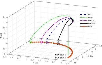
The quadrotor system is exposed to wind induced disturbance force in X direction. Four different conditions are considered in the simulations for wind induced disturbance force. At first, performance of the proposed FOFPID controller is examined in the absence of wind disturbance and is compared with the other controllers. Figure 7 shows translational motion of the quadrotor UAV and the UGV in the cartesian space within the first simulation.
Autonomous landing of quadrotor in the absence of wind disturbance. Symbols
 $ \vee $
and
 $ \otimes $
illustrate UAV and UGV position at the touchdown sequence of autonomous landing maneuver, respectively.

According to simulation results in Fig. 7, all of the controllers have successfully performed the autonomous landing maneuver while the proposed FOFPID controller is faster than the others.
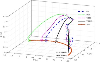
In the second simulation, the wind induced disturbance force is considered as a sine function (
 ${D_1} = 0.1{\rm{sin}}\left( {0.5t} \right)$
). Performance of the proposed controllers in the autonomous landing maneuver of quadrotor is demonstrated in Fig. 8 in the presence of wind induced disturbance
 ${D_1} = 0.1{\rm{sin}}\left( {0.5t} \right)$
.
Autonomous landing of quadrotor in the presence of wind disturbance
 ${{\rm{D}}_1} = 0.1sin\left( {0.5{\rm{t}}} \right)$
. Symbols
 $ \vee $
and
 $ \otimes $
illustrate UAV and UGV position at the touchdown sequence of autonomous landing maneuver, respectively.

Although all of the controllers have successfully performed the autonomous landing maneuver, the other controllers are more affected by wind disturbance. The proposed FOFPID controller provides faster and more robust responses for the under-actuated nonlinear system of the quadrotor.
In the following simulations, the quadrotor system is exposed to higher amplitude disturbance forces of
 ${D_2} = 0.2{\rm{sin}}\left( {0.5t} \right)$
and
 ${D_3} = 0.3{\rm{sin}}\left( {0.5t} \right)$
, respectively.
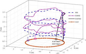
Performance of the controllers in the autonomous landing maneuver in the presence of wind disturbance of
 ${D_2} = 0.2{\rm{sin}}\left( {0.5t} \right)$
is depicted in Fig. 9. Fuzzy controller could not achieve and preserve rendezvous conditions in at least 500 s. Consequently, it has failed to perform autonomous landing maneuver in the presence of wind disturbance of
 ${D_2} = 0.2\sin \left( {0.5t} \right)$
.
Autonomous landing of quadrotor in the presence of wind disturbance of
 ${{\rm{D}}_2} = 0.2sin\left( {0.5{\rm{t}}} \right)$
. Symbols
 $ \vee $
and
 $ \otimes $
illustrate UAV and UGV position at the touchdown sequence of autonomous landing maneuver, respectively.

Simulation results in Fig. 9 reveal that the proposed FOFPID controller is more robust against the wind disturbance and very better preserve the rendezvous conditions. So that, it can perform autonomous landing maneuver in less time. Conventional PID and FOPID controllers are completely affected by wind disturbance and have lost the rendezvous conditions several times during simulation. Consequently, the quadrotor has landed on the moving platform in multiple attempts.
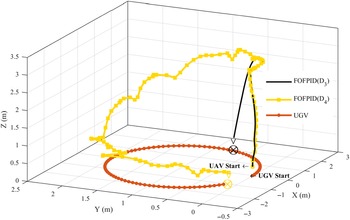
Performance of the proposed FOFPID controller against the wind disturbances
 ${{\rm{D}}_3} = 0.3sin\left( {0.5{\rm{t}}} \right)$
and
 ${D_4} = 0.4sin\left( {0.5{\rm{t}}} \right)$
. Symbols
 $ \vee $
and
 $ \otimes $
illustrate UAV and UGV position at the touchdown sequence of autonomous landing maneuver, respectively.

Performance of the proposed FOFPID controller is examined against the wind induced disturbance forces of
 ${D_3} = 0.3{\rm{sin}}\left( {0.5t} \right)$
and
 ${D_4} = 0.4{\rm{sin}}\left( {0.5t} \right)$
, and results are depicted in Fig. 10.
The tochdown position of the UAV and the UGV during autonomous landing maneuver.

The other controllers have failed to perform successful autonomous landing maneuver in at least 500 s. They could not achieve and preserve rendezvous conditions. Therefore, their trajectories are eliminated from the results.
The proposed FOFPID controller strongly resists the wind disturbance force and preserve rendezvous conditions. It could perform autonomous landing maneuver as fast as ideal conditions against the wind disturbance of
 ${D_3} = 0.3{\rm{sin}}\left( {0.5t} \right)$
. While it is considerably affected by the wind disturbance of
 ${D_4} = 0.4{\rm{sin}}\left( {0.5t} \right)$
and has lost the rendezvous condition several times. It has successfully performed the autonomous landing maneuver in 70 s against the strong wind disturbance of
 ${D_4} = 0.4{\rm{sin}}\left( {0.5t} \right)$
with the accuracy of
 ${r_x} = 0.14\;{r_y} = 0.04$
. The tochdown position of the UAV and the UGV during autonomous landing maneuver is reported in Table IV.
Tables V and VI give a comprehensive breakdown of the controllers’ performance in term of landing time and landing accuracy indexes where superior results are bolded. From the viewpoint of landing time, the proposed FOFPID controller has performed the best among the studied control methods. Clearly, the proposed FOFPID controller tries to perform the autonomous landing maneuver as fast as possible while scarifies the landing accuracy. It can be concluded that the proposed FOFPID control method provides fast and robust response simultaneously which is usually difficult to achieve with constant control gains for nonlinear under-actuated systems like quadrotors.
Performance of the proposed controllers in term of the landing time.

*Unsuccessful rendezvous.
Performance of the proposed controllers in term of the landing accuracy.

5. Conclusion
This research is concentrated on the design of an FOFPID controller for nonlinear under-actuated system of the quadrotor. Also, a supervisory control algorithm is proposed as autonomous landing path generator to perform fast, smooth, and accurate landing. On the other hand, a compound AprilTag fiducial marker is employed by the PBVS method to obtain the relative position of the landing pad which extends positioning range and enables high precision positioning both in short and long ranges.
SITL simulation method is realized on the windows platform to perform numerical simulations of the proposed PBVS control system. The quadrotor UAV is exposed to different wind-induced disturbance forces while the actuators dynamics are included in the quadrotor model to make a challenge with transient response and saturated output thrust of actuators. Simulation results reveal superior performance of the proposed FOFPID controller over the other ones in terms of landing time and landing precision indexes. The proposed FOFPID controller provides fast and more robust response for nonlinear under-actuated system of quadrotor which cannot be achieved by conventional PID controller.
The proposed FOFPID controller has more DOF for tuning and provides superior performance at the cost of more difficult and time-consuming manual tunings. In the future work, an adaptive gain scheduling method will be adopted to the FOFPID controller to overcome the labor of manual tuning and to improve system robustness against unknown time varying disturbances.
Acknowledgments
The authors would like to acknowledge financial support of the Islamic Azad University, North Tehran Branch (Grant No. 2691) for this research, which is based on a research project contract.