I. INTRODUCTION
Near-field (NF) coupling between antennas has been studied since a long time in the context of research activities on coupling effects in antenna arrays, field sensing for NF antenna scanning systems, and magnetic coupling between loops operating at the low-frequency (LF, 125–134 KHz) and high-frequency (HF, 13.56 MHz) industrial, scientific, and medical radio bands. More recently, the NF-coupling analysis has been applied to specific short-range radio systems, as, for example, NF communications [Reference Tucker, Muehlmann and Gebhart1], microwave wireless power transfer [Reference Gowda, Yurduseven, Lipworth, Zupan, Reynolds and Smith2, Reference Del Prete, Berra, Costanzo and Masotti3], intra-body communication for the Medical Device Radiocommunications Service (MedRadio) [Reference Moradi4], and radio frequency identification (RFID) systems [Reference Trevisan and Costanzo5, Reference Chen, Chen and Li6].
In LF/HF RFID systems, the reader-tag communication occurs through a NF inductive coupling, and antennas are usually made of single-/multi-turn coils at both reader and tag sides. LF/HF inductive couplings are robust with respect to the presence of metallic objects and conductive liquids in the tag vicinity [Reference Fotopoulou and Flynn7]. When compared with LF/HF RFID systems, ultra high frequency (UHF, 860–960 MHz) and microwave (2.4 and 5.8 GHz) RFID systems are characterized by larger reading range, reading rate, and data rate, but they are more sensitive to environmental effects such as line-of-sight obstruction, multipath phenomena, and presence of nearby objects exhibiting high dielectric permittivity and losses [Reference Nikitin, Rao and Lazar8]. To exploit the advantages of both LF/HF and UHF RFID systems, the NF UHF-RFID systems [Reference Nikitin, Rao and Lazar8, Reference Fuschini, Piersanti, Sydanheimo, Ukkonen and Falciasecca9] have been investigated for applications such as item-level tagging (ILT) in pharmaceutical and retail industries [Reference Buffi, Michel, Caso and Nepa10, Reference Cho, Lee, Ryoo and Choo11]. They combine the high data rate that is typical of UHF systems with the higher robustness to the environment effects of the LF/HF systems. Communication occurs in the reader antenna NF region through a NF electromagnetic coupling and the load modulation principle [Reference Nikitin and Rao12]. A NF UHF-RFID system can be realized by different approaches and, according to the classification proposed in [Reference Nikitin, Rao and Lazar8, Reference Fuschini, Piersanti, Sydanheimo, Ukkonen and Falciasecca9], they can be subdivided into the following ones:
-
I. Using conventional UHF-RFID readers and tags, with low-power levels at the reader output; by reducing the power radiated by the reader antenna, the read range decreases and only the tags close to the reader antenna will be detected.
-
II. Using ad hoc tags: tags properly designed to maximize the magnetic coupling, or intentionally mismatched, are detected only if they are close to the reader antenna. Such an approach is specific for the ITL of objects that are small with respect to conventional UHF-RFID tags, as, for example, medicines or mechanical tools [Reference Jaakkola and Koivu13, Reference Turalchuk, Munina, Derkach, Vendik and Vendik14].
-
III. Using ad hoc reader antennas: planar reader antennas are properly designed to shape and limit the near field, so reducing the false-positive readings of tags located far from the reader antenna surface [Reference Michel, Caso, Buffi, Nepa and Isola15–Reference Michel, Rodriguez Pino and Nepa17].
In this context, most of numerical results here presented refer to the first case, although the tags involved in the analysis are commercialized as UHF-RFID tags exhibiting good performance in both NF and far-field applications [18, 19]. Nonetheless, the specific case with a reader antenna identical to the commercial tag antenna belongs to the approach where an ad hoc reader antenna is used.
Besides the NF UHF-RFID systems, other UHF RFID applications where the NF coupling between the reader and tag antennas can arise are those related to item-tracking on conveyor belts [Reference Liu and Hillegas20], desktop readers [Reference Michel, Caso, Buffi, Nepa and Isola15–Reference Michel, Rodriguez Pino and Nepa17], smart shelves [Reference Medeiros, Costa and Fernandes21], printer encoders [Reference Tsirline, Hohberger, Gawelczyk and Donato22, Reference Michel, Buffi, Nepa and Manara23], smart systems for indoor tracking [Reference Catarinucci24].
In NF-coupling scenarios, the Friis equation and the conventional far-field antenna parameters, as the gain patterns and the polarization-mismatching coefficient, are not suitable to characterize the radio link. The analytical evaluation of the NF electromagnetic coupling is a quite challenging task, and some results are limited to configurations involving simple antenna models. In [Reference Fuschini, Piersanti, Sydanheimo, Ukkonen and Falciasecca9], the reciprocity theorem has been used to evaluate the NF coupling between a few antenna models for which a known current source distribution can be assumed. In [Reference Yates, Holmes and Burdett25], a NF coupling coefficient has been calculated through a series expansion, starting from the vector expression of the far-field radiation. On the other hand, maximizing the wireless power transfer between reader and tag represents a key issue in improving the performance of actual RFID systems, as well as in facing with novel challenging RFID applications. To account for the influence of different antenna layouts and their relative orientations/positions, full-wave numerical simulations are preferred as they give more general and practical results. Indeed, the NF coupling is determined by the behavior of all NF components of both the electric and magnetic fields, and it is specific for each antenna layout. Then, considering realistic tag and reader antennas instead of simplified models is mandatory when trying to quantify the wireless power transfer in real-word applications. Numerical simulations are also convenient with respect to expensive and time-consuming measurement campaigns, which can be obtained only for a limited set of reader-tag antenna pairs.
In this paper, a preliminary numerical analysis for NF UHF-RFID systems is addressed, through full-wave numerical simulations and by referring to a set of commercial tag antennas. Typical UHF-RFID commercial antennas like patches and slot antennas are also employed at the reader side, together with loop antennas as already considered in the preliminary results shown in [Reference Buffi, Nepa and Manara26]. Additionally, the case of a reader antenna identical to the tag antenna has been considered, which has been referred as the “shape-matched antenna” configuration. In this context, the power transfer efficiency (PTE) in RFID systems using identical antennas at the tag and reader sides have also been studied in [Reference Chen, Chen and Li6], by referring to two conventional dipoles or loops instead of pairs of commercial UHF-RFID tag antennas.
The PTE has been evaluated by using an equivalent impedance matrix model for the electromagnetic coupling between the reader and tag antennas, where the matrix entries are calculated through the ANSYS™ commercial numerical code.
To allow for a comparison between different antenna pairs, a benchmarking impedance loading condition has been considered at the tag side. Specifically, the optimum load in [Reference Bird, Rypkema and Smart27] has been assumed, which allows to get an upper bound for the PTE. A more realistic loading condition refers to a load impedance equal to the conjugate of the tag antenna input impedance. The paper is concerned with the most critical link of the tag-reader communication, namely the forward link (or downlink) [Reference Kuester, Novotny and Guerrieri28]. Indeed, it is during this phase that the passive tag is activated by the reader radiation through wireless powering. It is also worth noting that the case under analysis is different from an energy harvesting scenario where the energy is captured from ambient sources, as, for example, solar power, thermal or wind energy, human or machine kinetic activities.
The paper structure is as follows. The impedance matrix Z of an equivalent two-port circuit made of the two nearby reader and tag antennas is briefly introduced in Section II. In Section III, reader and tag antennas used to get the numerical results are described, together with some of their main characteristic parameters. In Section IV, the “shape-matched antenna” configuration is described and some preliminary results in terms of mutual coupling are shown. PTE curves for different antenna pairs are presented in Section V. Concluding remarks are drawn in Section VI.
II. NF UHF-RFID COUPLING MODEL
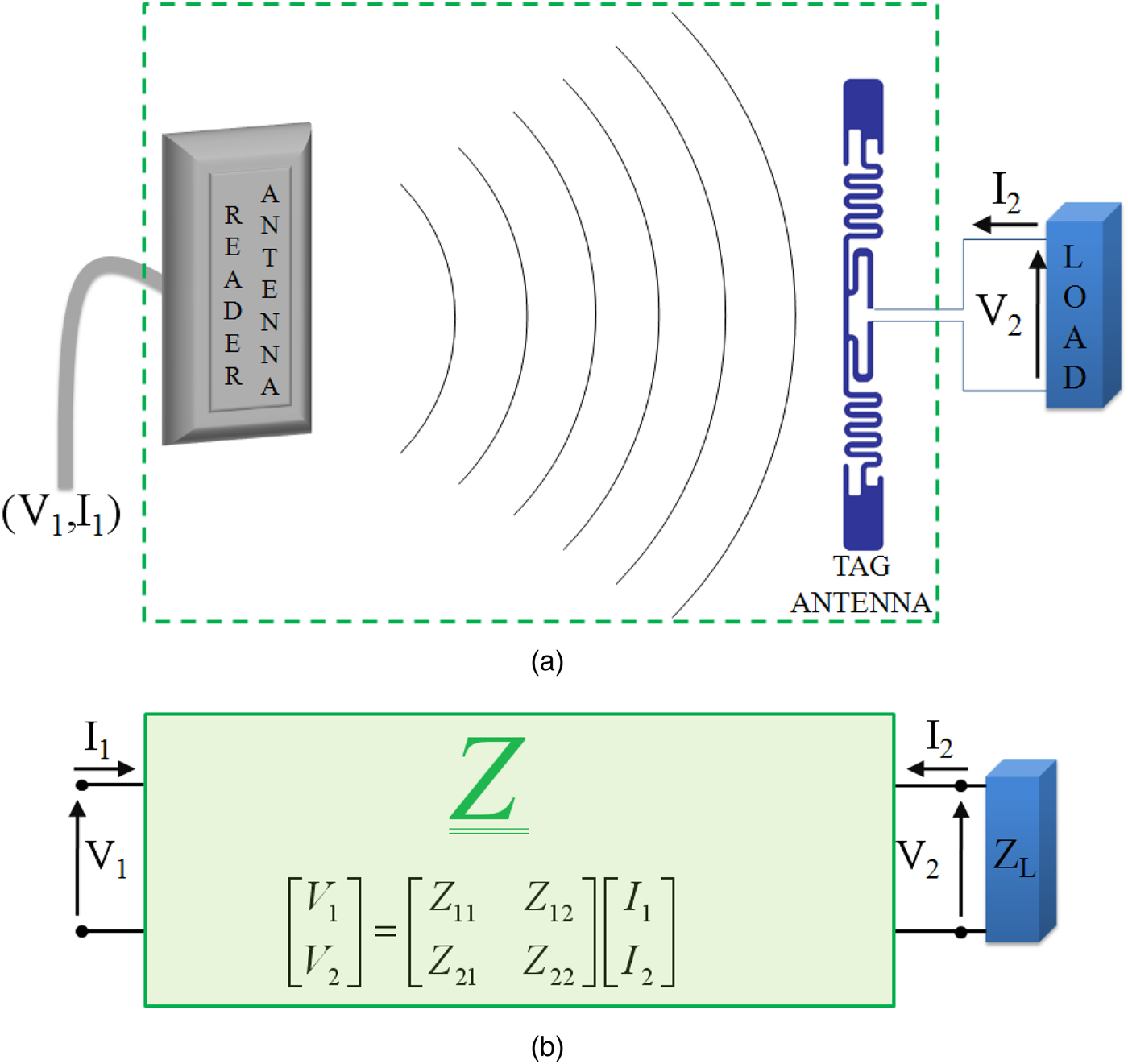
The impedance matrix model adopted for the analysis of the NF UHF-RFID forward link is shown in Fig. 1. It results from considering the tag and reader antennas as a two-port linear network (throughout the manuscript, indexes 1 and 2 refer to the reader and tag ports, respectively).
(a) The scheme of a NF UHF-RFID system, with the tag antenna connected to a load representing the RFID chip and (b) the equivalent two-port linear network described by the impedance matrix Z . ZL denotes the tag load impedance.
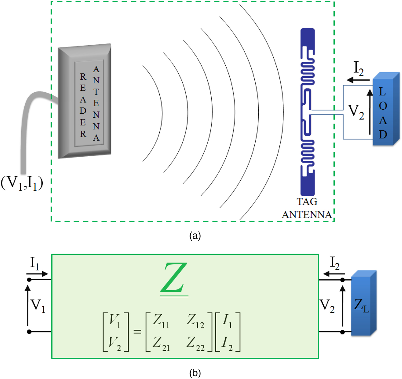
In the typical configuration shown in Fig. 1(a), the tag antenna is directly connected to a load that is the RFID chip, without any transmission line. In addition, the tag antenna is designed so that its input impedance resembles the conjugate of the ohmic-capacitive chip equivalent impedance. In this preliminary numerical analysis, the non-linear behavior of the RFID chip has been neglected. Besides, environmental phenomena, like multipath or the presence of material objects close to the antennas, are not considered, as their effect will deserve an analysis significantly dependent on the specific obstacle/environment surrounding the tag vicinity and the object the tag is placed on.
As a figure-of-merit of the wireless power transfer between the reader and tag antennas, both the mutual-impedance (Z
21 of the impedance matrix) and the PTE have been analyzed. Z
21 = Z
12 is equal to the open-circuit voltage at the antenna tag side normalized to the input current at the reader antenna, and it is independent of the tag antenna loading. The PTE is defined as the ratio between the power absorbed by the tag antenna load (namely, the power given to the RFID chip),
 $P_T = 1/2\Re \{ Z_L \} \vert I_2 \vert ^2 $
, and the input power accepted by the reader antenna,
 $P_R = 1/2\Re \{ Z_{in} \} \vert I_1 \vert ^2 $
:
 $$PTE = \displaystyle{{P_T} \over {P_R}} = \displaystyle{{(1/2)\Re \{ Z_L \} \vert I_2 \vert ^2} \over {(1/2)\Re \{ Z_{in} \} \vert I_1 \vert ^2}}, $$
where Z in is the input impedance of the two-port network at port 1, calculated as Z in = Z 11 − Z 12 Z 21/(Z 22 + Z L ). By combining the two following equations for the voltage at port 2, V 2 = Z 21 I 1 + Z 22 I 2 and V 2 = −Z L I 2, it is possible to derive that I 2/I 1 = −Z 21/(Z L + Z 22), and then the PTE expression in terms of the impedance matrix entries and tag impedance load results as:
 $$PTE = \vert Z_{21} \vert ^2 \displaystyle{{\Re \{ Z_L \} /\Re \{ Z_{in} \}} \over { \vert Z_L + Z_{22} \vert ^2}}. $$
It is worth noting that P R is the net power absorbed by the reader antenna. This means that the impedance mismatching at the reader side is not considered or, equivalently, it is assumed that an adaptive lossless impedance network is inserted between the reader output and the reader antenna. The power absorbed by the tag P T has to be equal or greater than the chip sensitivity to power-up the tag itself.
Let us denote the input impedance for the stand-alone reader and tag antennas as Z R and Z T , respectively (note that they are frequency-dependent). The diagonal terms of the impedance matrix, namely the self-impedances Z 11 and Z 22, approach Z R and Z T , respectively, when each antenna can be considered in the far-field region of the other one. For the definition of antenna far-field region, the reader can refer to any book on antenna theory [Reference Balanis29]. Nonetheless, numerical results in Section III will show that, for the antenna layouts here considered, it can be assumed that the NF coupling can be simplified with a simpler far-field coupling model when the antenna separation is larger than one wavelength.
While the mutual impedance, Z 21 = Z 12, only depends on the relative orientation/position of the reader and tag antennas [Reference Stubenrauch and Francis30], the PTE is a function the tag antenna loading too, as apparent from equation (2). To allow for a comparison between different antenna pairs, a specific tag loading condition has been assumed, Z L = Z opt = R opt + jX opt , which guarantees the maximum PTE for a given set of impedance matrix entries Z ij = R ij + jX ij . Specifically, the Linville load [Reference Bird, Rypkema and Smart27] is given by:
 $$R_{opt} = \sqrt {\eqalign{&R_{22} ^2 - R_{22} (R_{12} R_{21} - X_{12} X_{21} )/R_{11} \cr&- (R_{12} X_{21} + R_{21} X_{12} )^2 /(4R_{11}^2 ),}} $$
 $$X_{opt} = - X_{22} + (R_{12} X_{21} + R_{21} X_{12} )/2R_{11}, $$
and the corresponding PTE will be denoted as PTE max :
 $$PTE_{max} = PTE(Z_L = Z_{opt} ).$$
It is worth noting that the analytical expression of the Linville load is valid for any separation between the two antennas, as it refers to a general two-port network.
To consider a more realistic case, PTE numerical results are also shown when the tag load impedance equals the conjugate of the input impedance of the stand-alone tag antenna, Z
T
, with the latter being evaluated at an assigned frequency f
0:
 $Z_L = Z_T^* (f = f_0 )$
. Indeed, this is the design criteria commonly applied for commercial tag antennas. The PTE for the above conjugate-impedance matching case is denoted as PTE
im
:
 $$PTE_{im} = PTE(Z_L = Z_T^* (f = f_0 )).$$
Since above conjugate-matched loading maximizes the PTE when f = f 0 and the two antennas operate in the far-field region, PTE max approaches PTE im when the antenna separation increases and f is close to f 0. From a numerical point of view, it happens that Z opt tends to Z 22* and Z 22 approaches Z T .
III. READER AND TAG ANTENNAS
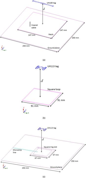
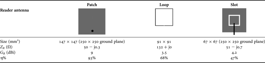
The reader antennas used in the numerical analysis are a square patch, a square loop and a square ring slot, so including most of the technologies used in commercial reader planar antennas. In the following, we briefly refer to them as patch, loop, and slot antennas. All antennas exhibit an input impedance close to 50 Ω in the UHF-RFID frequency band with a resonance frequency at around f 0 = 910 MHz. The coaxial-fed patch antenna (Fig. 2(a)) is 147 mm × 147 mm large, with a 250 mm × 250 mm ground plane positioned at a distance of 20 mm. The loop antenna (Fig. 2(b)) has a width of 2 mm with a perimeter of 364 mm, which roughly corresponds to the value of the wavelength at the UHF-RFID central frequency: λ 0 = 0.33 m. The slot antenna (Fig. 2(c)) is realized on a 1.6 mm-thick FR-4 substrate and it is fed with a microstrip line. It is 8 mm-wide with a perimeter of 268 mm. The ground plane measures 250 mm × 250 mm. The reader antennas and their main electrical and geometrical parameters are summarized in Table 1. The simulated input impedance, the gain, and the radiation efficiency of the stand-alone reader antennas are calculated at the resonance frequency f 0 = 910 MHz. As far as the radiation efficiency is concerned, it is worth noting that a high antenna radiation efficiency is needed to maximize PTE.
NF UHF-RFID configurations: (a) Patch/UH100, (b) Loop/UH113, and (c) Slot/UH113. Sizes are not in scale.

Reader antenna size, and simulated input impedance, realized gain and radiation efficiency, at f 0 = 910 MHz (results are for the stand-alone reader antenna).

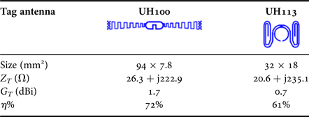
The tags we considered are listed in Table 2, together with their simulated parameters: UH113 [18] and UH100 [19]. The UH113 is the smallest one (32 mm × 18 mm) and is based on a hybrid dipole-loop configuration. The central loop (whose radius is around 7 mm) is used to get the impedance matching with the ohmic-capacitive chip impedance, as well as to generate a strong NF magnetic coupling with the reader interrogation field [Reference Marrocco31], just like in LF/HF systems. Indeed, it is classified as a tag with good performance in both far field and NF regions [18]. The UH100 tag is a 94 mm × 7.8 mm meandered dipole. Even in this case, the presence of the central loop (18 mm × 7.6 mm) allows to get a satisfactory NF performance [19]. For all reader and tag antenna models, a 0.035 mm thick copper layer has been assumed.
Tag antenna size, and simulated input impedance, realized gain, and radiation efficiency, at f 0 = 910 MHz (results are for the stand-alone tag antenna).

To limit the number of configurations under analysis, we only considered linearly polarized reader antennas and the tag orientation corresponding to the far-field polarization matching condition.
The numerical model for each tag antenna has been extracted from tag samples [18, 19]. We noted a small discrepancy between the numerical values of Z T and the complex conjugate of the input impedance of the corresponding tag chip (the latter as extracted from tag datasheet [32], if available). This can be related to a number of issues: both tag and chip impedances vary significantly in the UHF-RFID frequency band; the chip input impedance actually represents the equivalent input impedance of a non-linear electronic front-end; finally, the numerical model we extracted from the tag samples may be affected by some tolerance errors (although we did our best to get them below 1 mm).
As an example of the simulated reader and tag antenna pairs, some geometries are depicted in Fig. 2: the patch antenna with the UH100 tag (Patch/UH100); the loop and slot antennas with the UH113 tag (Loop/UH113 and the Slot/UH113). All the antennas lye on parallel planes, and they are aligned to meet the polarization matching condition in case of a hypothetical far-field condition.
The first numerical tests focus on finding the minimum distance d between the reader and the tag antennas beyond which both the following approximations can be assumed as valid:
-
(a) the self-impedances, Z 11 and Z 22, can be considered independent of the distance;
-
(b) the mutual-impedance, Z 12 = Z 21, exhibits a 1/d algebraic decay, namely a 20 dB/decade amplitude decay typical of the antenna coupling in the far-field region.
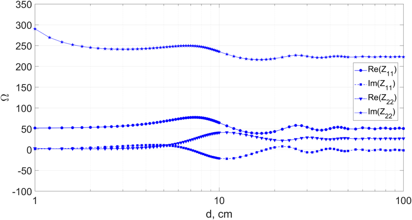
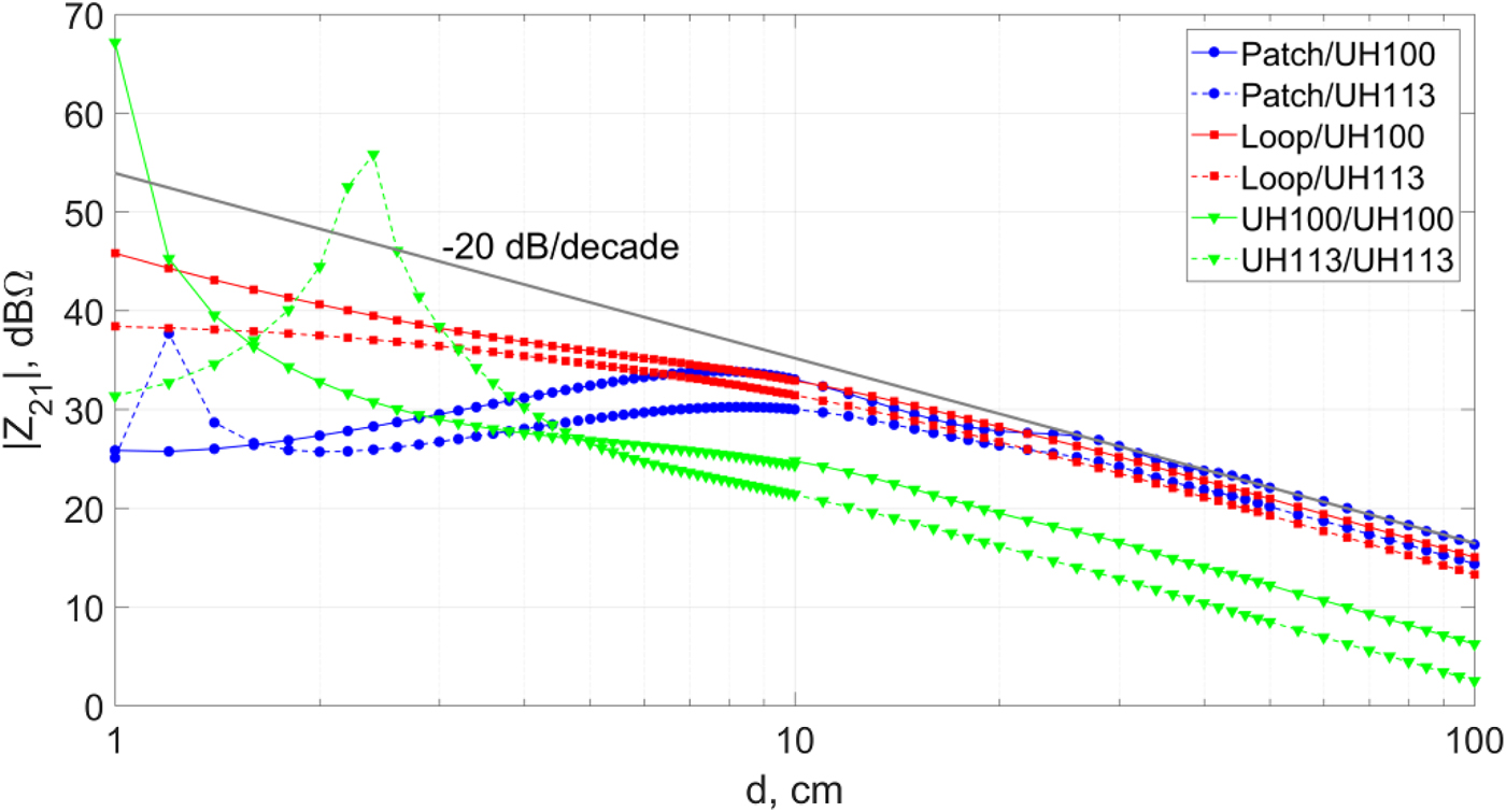
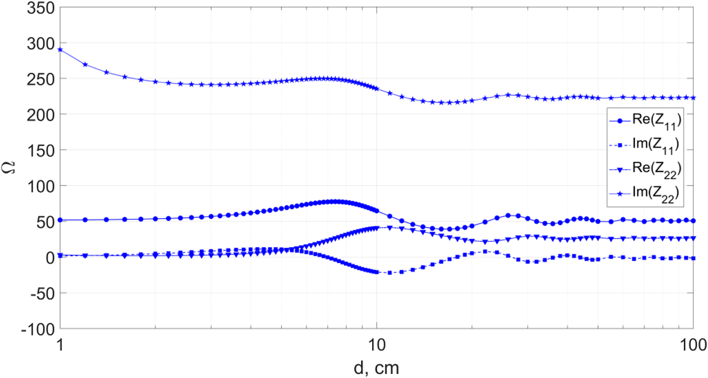
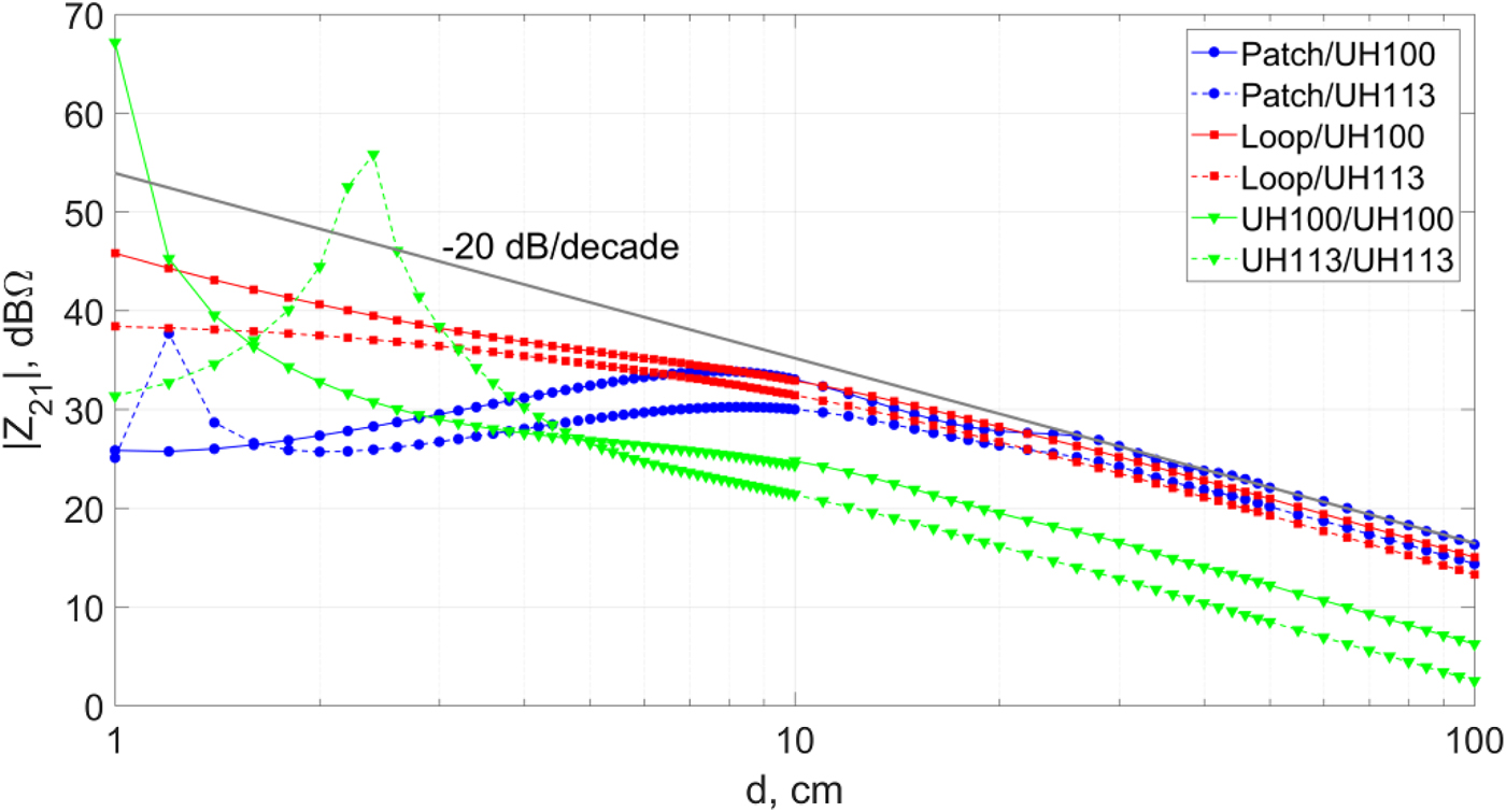
Figure 3 shows the self-impedances at 910 MHz, by referring to the antenna pair Patch/UH100 in Fig. 2(a). After some oscillations, beyond d = 30 cm the self-impedance approaches a constant value. Figure 4 shows the mutual impedance Z 21 for the following antenna pairs: Patch/UH100, Patch /UH113, Loop/UH100, and Loop/UH113. In Fig. 4, the results for the “shape-matched antenna” configurations have also been included (UH100/UH100 and UH113/UH113). At distances greater than d = 30 cm, all curves approach a 1/d algebraic decay. By considering the behavior of the above curves, it could be stated that the boundary of the far-field region is at around d FF = 30 cm (around 0.9λ, at 910 MHz). After considering all possible combinations of the antennas in Tables 1 and 2, for a set of frequencies in the whole 860–960 MHz range, it is here assumed that the electromagnetic coupling between the reader and tag antennas behaves as a simpler far-field coupling for antenna separations larger than one wavelength. This result agrees with the antenna basic theory for antennas smaller than one wavelength [Reference Balanis29].
Real and imaginary parts of the self-impedances, Z11 and Z22, versus the antenna separation, for the Patch/UH100 configuration, at f 0 = 910 MHz.
Amplitude of the mutual impedance, Z 21, versus the antenna separation, evaluated at f 0 = 910 MHz, for the following configurations: Patch/UH100 (circle-marker solid line), Patch/UH113 (circle-marker dashed line), Loop/UH100 (square-marker solid line), Loop/UH113 (square-marker dashed line), UH100/UH100 (triangle-marker solid line), UH113/UH113 (triangle-marker dashed line).
IV. “SHAPE-MATCHED” READER ANTENNA
As mentioned in Section I, a NF UHF-RFID system can also be implemented through an ad hoc reader antenna. Thus, besides conventional reader antennas, the employment of a reader antenna equal to the tag antenna is here investigated. In wireless applications, choosing identical (or quite similar) antennas to increase the antenna NF coupling is not a novelty. In this context, some well-known examples are a pair of either loops or dipoles used at the receiver and transmitter sides of short-range LF/HF radio links, or the Yagi-Uda antenna parasitic directors whose size is close to that of the driven element. More recently, a reader antenna identical to the tag antenna has been proposed for UHF-RFID printer encoders, where the tags to be encoded are at a few millimeters only from the reader antenna [Reference Michel, Buffi, Nepa and Manara23].
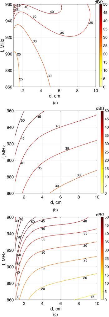
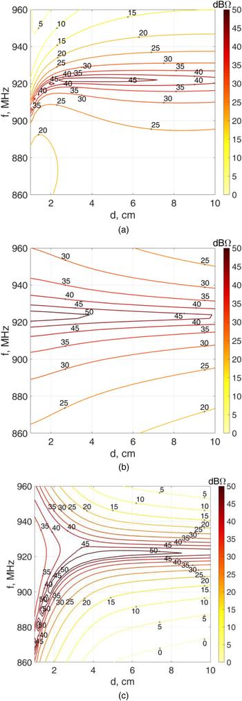
To illustrate the |Z 21| features for the NF coupling between two identical tag antennas, some numerical results are shown in Fig. 4 (green curves with triangle markers). At the central frequency of 910 MHz, the “shape-matched antenna” configuration shows quite high mutual-impedance values, and a peak coupling distance is apparent: d peak = 1 cm and d peak = 2.4 cm, for the UH100/UH100 and UH113/UH113 cases, respectively. In Figs 5 and 6, contour plots of the Z 21 mutual impedance as a function of the antenna separation between 1 and 10 cm are shown in the whole UHF-RFID frequency range, and for six different antenna pairs. Results related to the slot antenna are similar to those obtained for the loop, and they are not shown for the sake of brevity. From above results, it appears that a frequency corresponding to a peak of the Z 21 amplitude can be found for almost any assigned antenna separation that is less than a few centimeters. Such behavior looks like a resonant condition and is more pronounced for the “shape-matched antenna” configuration, especially when the smallest tag is considered (UH113). However, the results in the next section show that above resonant condition disappears when considering the PTE max curves, as the PTE is proportional to the square of |Z 21| through a coefficient that includes the ratio between a number of impedance values (see equation (2)).
Contour plot of the amplitude of the mutual impedance Z 21 (dBΩ) versus the antenna separation and the frequency, for some NF UHF-RFID antenna configurations: (a) Patch/UH100, (b) Loop/UH100, and (c) UH100/UH100.

Contour plot of the amplitude of the mutual impedance Z 21 (dBΩ) versus the antenna separation and the frequency, for some NF UHF-RFID antenna configurations: (a) Patch/UH113, (b) Loop/UH113, and (c) UH113/UH113.

V. PTE RESULTS
Figure 7 presents the PTE calculated through equation (2), when either Z
L
= Z
opt
(PTE = PTE
max
) or
 $Z_L = Z_T ^* (f = f_0 )$
(PTE = PTE
im
), at the central frequency f
0 = 910 MHz, as a function of the antenna separation. We briefly refer to them as PTE
max
and PTE
im
.
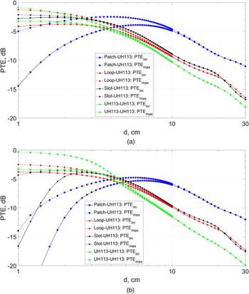
PTEim (solid line) and PTEmax (dashed line) versus antenna separation for the following NF UHF-RFID system configurations: (a) Patch/UH100 (circle-marker), Loop/UH100 (square-marker), Slot/UH100 (star marker) and UH100/UH100 (triangle marker), (b) Patch/UH113 (circle-marker), Loop/UH113 (square-marker), Slot/UH113 (star marker), and UH113/UH113 (triangle marker).

It is worth noting that the theoretical upper bound of PTE max = 0 dB can be approached when considering two lossless antennas that are electrically small (l ≤ 0.1λ), since the radiation power becomes negligible with respect to the transmitted power [Reference Lee and Nam33]. For the UH113 tag, which is near 0.1λ wide, a PTE max = −0.3 dB is reached in the “shape-matched antenna” configuration. A lower value equal to PTE max = −0.9 dB is reached for the UH100 tag, whose size goes up to 0.3λ. By considering the global behavior of the PTE max curves, it appears that the “shape-matched antenna” configuration allows maximizing the PTE max for small antenna separations. As the distance increases, the PTE max approaches the value that can be evaluated through the Friis formula, and the largest values are those for the configurations including the patch antenna, as the latter exhibits the largest far-field gain. On the contrary, the smallest PTE max values are those for the “shape-matched antenna” configuration, which includes two antennas with the lowest gain.
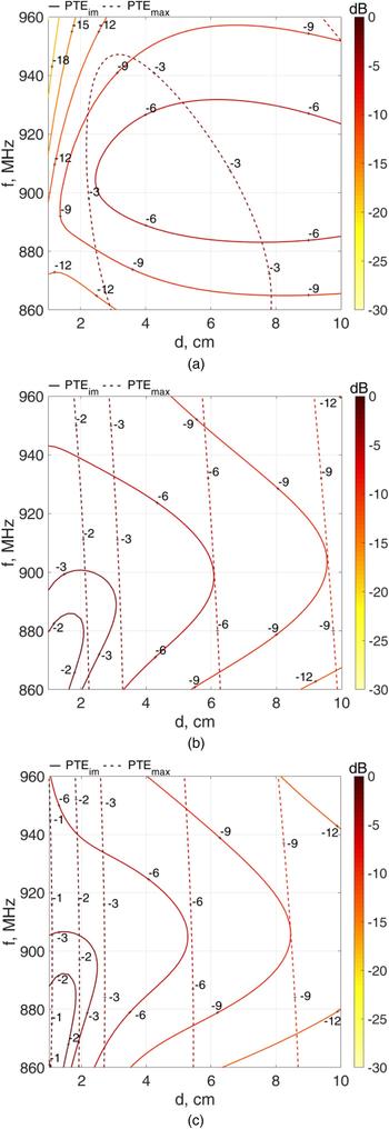
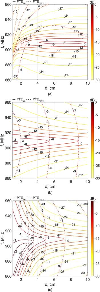
A larger set of numerical results are shown in Figs 8 and 9, where PTE max and PTE im are evaluated for separation distances in the range from 1 to 10 cm and within the whole UHF-RFID frequency bandwidth, for six different antenna pairs. If the patch is used as a reader antenna, the PTE max tends to vanish when the tag approaches the patch surface. This is not the case for all other reader antennas here considered. At small distances, the PTE max results are usually slightly larger for the “shape-matched antenna” configuration with respect to the loop (and slot too, although not explicitly shown in those figures). On the other hand, in the “shape-matched antenna” configuration, the antenna used at the reader side is more compact with respect to the loop and slot antennas, and the above mentioned low PTE value at large distances helps to reduce the false-positive readings. Both above advantages can be exploited in RFID readers for either tag checking at the manufacturer production lines or printer encoders [Reference Michel, Buffi, Nepa and Manara23], where a specific relative position/orientation between the two antennas is determined by the system mechanical parts, and the reader antenna compactness is mandatory.
Contour plot of the PTEim (solid line) and of the PTEmax (dashed line) versus antenna separation and frequency, for the following NF UHF-RFID system configurations: (a) Patch/UH100, (b) Loop/UH100, and (c) UH100/UH100.

Contour plot of the PTEim (solid line) and of the PTEmax (dashed line) versus antenna separation and frequency, for the following NF UHF-RFID system configurations: (a) Patch/UH113, (b) Loop/UH113, and (c) UH113/UH113.

When comparing the curves for PTE max and PTE im , for a specific antenna pair, it appears that PTE im approaches PTE max when f = f 0 = 910 MHz and for the larger distances, as expected. Only a relatively small PTE reduction is noted when the antenna separation reduces, as soon as the operating frequency remains around 910 MHz, especially for the smallest tag (UH113). This positive effect is probably related to the resonance induced at the tag side by the conjugate–impedance condition.
VI. CONCLUSION
In the context of the forward link in NF UHF-RFID systems, this paper presented a preliminary numerical analysis of the wireless power transfer between the reader and tag antennas. Since the two antennas are very close, far-field coupling models are useless; then, the impedance matrix associated to an equivalent two-port linear model has been used, where the mutual- and self-impedances are calculated through a full-wave numerical tool. Since the NF coupling is strongly related to the antenna layouts, the tag antenna models here considered are those of typical commercial UHF-RFID tags, instead of simple loop or dipole antennas. Even the reader antenna models are representative of typical commercial reader antennas. The numerical analysis has been carried out by considering different reader antenna/tag pairs, by varying the antenna separation and the operating frequency within the UHF-RFID frequency band. To allow for a comparison between different antenna pairs, numerical data have been calculated when the tag loading impedance is that one that maximizes the PTE. A more realistic condition, namely the conjugate–impedance matching, has also been considered to estimate the performance drop with respect to the above optimal case.
This preliminary analysis demonstrated that the configuration where an ad hoc reader antenna is chosen as identical to the tag antenna (“shape-matched antenna” configuration) can guarantee similar or better performance than conventional antennas (like patches, loops, and slots), at least when the antenna separation is of the order of a few centimeters or less, and the antenna is more compact too.
Environmental phenomena, like multipath or the presence of material objects close to the antennas, have not been considered in the present paper, as their effect will deserve an analysis significantly depending on the specific obstacle/environment surrounding the tag vicinity and the object the tag is placed on. Nonetheless, in the cases here considered, the tag is at a few centimeter only from the reader antenna and then it is expected that the multipath effect is negligible with respect to the direct NF coupling mechanisms.
Future work will be devoted to a more detailed analysis of the “shape-matched antenna” configuration. That study will include the effect of the matching network required to match the ad hoc tag-like antenna to the typical 50-Ω output impedance of commercial readers, as well as the presence of obstacles close to the antenna pair and the variations induced by the antenna reciprocal orientations/positions.
ACKNOWLEDGEMENTS
The authors would like to thank LAB ID srl, Bologna, Italy (http://www.lab-id.com), for providing some tag samples.
CONFLICT OF INTEREST
None.
 Alice Buffi received the bachelor and master (summa cum laude) degrees in Telecommunications Engineering from the University of Pisa, Pisa, Italy, in 2006 and 2008, respectively. During the undergraduate course, she attempted additional classes to get the Percorso di Eccellenza Award. She received the Ph.D. degree in Applied Electromagnetism from the University of Pisa in 2012, with Doctor Europaeus label. She is currently a Post-Doctoral Researcher with the Department of Information Engineering, University of Pisa. She was a Visiting Ph.D. Student with the Queen Mary University of London, London, UK, in 2012. Her research interests include design of near-field focused microstrip arrays and microstrip antennas, near-field coupling in UHF-RFID systems and wireless power transfer, antenna design for UHF-RFID readers, and new phase-based localization techniques for RFID systems. Dr. Buffi was a recipient of the Young Scientist Award from the International Union of Radio Science, Commission B, in 2013 and 2016.
 Andrea Michel received the M.E. and Ph.D. degrees in Telecommunications Engineering from the University of Pisa, Italy, in 2011 and 2015, respectively. Since 2015 he is a Post-Doctoral Researcher with the Department of Information Engineering, University of Pisa. His research topics focus on the design of antennas for communication systems and near-field UHF-RFID systems. In 2014, he was a Visiting Scholar at the ElectroScience Laboratory, the Ohio State University, Columbus, OH, USA. During this period, he has been involved in research on a theoretical analysis on the accuracy of a novel technique for deep tissue imaging. Recently, he is involved on the design of antennas for automotive applications and wearable communication systems. Dr. Michel was a recipient of the URSI Young Scientist Award in 2014, 2015, and 2016. In 2016, he received the Best Paper Honorary Mention from the IEEE International Conference on RFID-TA, Shunde, China.
 Paolo Nepa is an Associate Professor at the University of Pisa. He co-authored more than 200 scientific papers on journals and international conference proceedings, regarding high-frequency asymptotic techniques, antenna design for mobile communications, radiolocalization techniques, RFID systems, wearable antennas, and on-body wave propagation modeling. He serves as an Associate Editor for IEEE Antennas and Wireless Propagation Letters.
 Giuliano Manara is a Professor at the College of Engineering of the University of Pisa, Italy. Since 1980, he has been collaborating with the Department of Electrical Engineering of the Ohio State University, Columbus, Ohio, USA, where, in the summer and fall of 1987, he was involved in research at the ElectroScience Laboratory. His research interests include numerical, analytical and hybrid techniques (both in frequency and time domain), frequency selective surfaces (FSS), electromagnetic compatibility, the design of microwave antennas with application to broadband wireless networks, the development and testing of new microwave materials (metamaterials), the analysis of antennas, and propagation problems for radio frequency identification (RFID) systems. Prof. Manara was elected as an IEEE (Institute of Electrical and Electronic Engineers) Fellow in 2004. He served as the International Chair of URSI (International Radio Science Union) Commission B for the triennium 2011–2014. Prof. Manara has been elected as a URSI Fellow in 2017.