1 Introduction
Gravity driven flows such as debris flows, sub-aerial and submarine landslides play a key role in erosion processes on the Earth’s surface. They represent one of the major natural hazards threatening life and property in mountainous, volcanic, seismic and coastal areas, as shown recently by the debris flows that occurred in Uganda and Brazil in 2010, causing 400 and 350 deaths respectively and displacing several hundred thousand inhabitants.
One of the ultimate goals of landslide studies is to produce tools for the prediction of velocity and runout extent of rapid landslides. The development of a theoretical description and physical understanding of the associated processes in a natural environment remains an unsolved and extremely challenging problem in Earth science, mechanics and mathematics. Recent progress in the mathematical, physical and numerical modelling of gravity driven flows has led to the development and use of numerical models for the investigation of geomorphological processes and the assessment of risks related to such natural hazards. However, severe limitations prevent us from fully understanding the physical processes acting in natural flows and from predicting landslide dynamics and deposition. One of the important issues is that existing models do not accurately account for the coexistence and interaction of fluid (water and gas) and solid granular phases within the flowing mass, which play a key role in natural gravity related instabilities. Water is almost always present in natural landslides, and the frequently resulting debris flows (mixture of water and grains) are often highly destructive.
The interaction between the fluid and granular phases within a saturated mixture essentially depends on the fluid pressure, also called pore pressure, which determines the effective friction force acting on the granular medium (e.g. Iverson Reference Iverson2000; Jackson Reference Jackson2000; Iverson Reference Iverson2005). Since the pioneering work of Reynolds (Reference Reynolds1885), a large number of studies have been dedicated to dilatancy effects in granular materials and to their interaction with pore fluid pressure, solid pressure and strain rates (e.g. Schofield & Wroth Reference Schofield and Wroth1968; Jackson Reference Jackson and Meyer1983; Bolton Reference Bolton1986; Vardoulakis Reference Vardoulakis1986; Wood Reference Wood1990; Mitchell Reference Mitchell1993). A change in the fluid pressure may result from a dilation of the granular phase, which induces a sucking of the fluid within the mixture and a diminution of the fluid pressure, thereby increasing the effective friction on the granular phase. On the other hand, a contraction of the granular phase induces an expulsion of the fluid from the mixture and an increase of the fluid pressure, thereby decreasing the effective friction. This process is sometimes called ‘pore pressure feedback’ (Iverson Reference Iverson2005). Contraction of a grain–fluid mixture may lead to liquefaction of the mixture. Dilation and contraction occur in response to a deformation of the granular medium, and in particular to shearing. Indeed, a densely packed granular assembly (high solid volume fraction) must dilate to be sheared, in order for the grains to have room enough to move one with respect to the other. On the other hand, a loosely packed assembly contracts in response to shearing. These processes play a dramatic role in the dynamics of fluidized granular flows, from their initial destabilization to their final deposition (Iverson et al. Reference Iverson, Logan, LaHusen and Berti2010; George & Iverson Reference George and Iverson2011; Rondon, Pouliquen & Aussillous Reference Rondon, Pouliquen and Aussillous2011; Montserrat et al. Reference Montserrat, Tamburrino, Roche and Niño2012; Andreini, Ancey & Epely-Chauvin Reference Andreini, Ancey and Epely-Chauvin2013; Iverson & George Reference Iverson and George2016).
It is a crucial issue to take dilatancy effects into account in numerical models of granular flows. However, solution of the complete three-dimensional (3D) equations of granular mass motion, with sufficient resolution to describe the real topography, requires prohibitive computational costs. For this reason, it is necessary to write simplified models. A class of efficient techniques, developed and successfully employed to reproduce a large range of experimental and geological observations, makes use of a depth-averaged continuum description, based on the thin-layer approximation (i.e. the thickness of the flowing mass is assumed to be small compared with its downslope extension) (Savage & Hutter Reference Savage and Hutter1989). This leads to the assumption that the velocity normal to the topography is small compared with the downslope velocity. Taking into account two-phase grain–fluid mixtures and dilatancy in the thin-layer approximation raises significant mathematical difficulties because of the need for a consistent description of these effects within this approximation. In particular, contraction–dilation induces a relative motion of the fluid and solid phases in the direction normal to the topography, which is formally small in the thin-layer asymptotic expansion. The drag friction force between the fluid and solid phases is, however, strong enough to make it important to take this relative motion into account in the asymptotic model, as detailed in this paper.
The solid–fluid mixture models described in the literature are generally based on Jackson’s model (Jackson Reference Jackson2000), which describes the main interactions between the two phases, such as buoyancy and drag frictional forces. Setting apart rheological laws, the main equations in Jackson’s model are mass and momentum conservation for the two phases, thus eight scalar equations. It has nine principal unknowns: the solid volume fraction, the solid and fluid pressures and the components of the solid and fluid velocities. As a result, a scalar closure equation is necessary to complete the model. Several depth-averaged thin-layer models have been deduced from Jackson’s model (e.g. Pitman & Le Reference Pitman and Le2005; Pelanti, Bouchut & Mangeney Reference Pelanti, Bouchut and Mangeney2008; Pailha & Pouliquen Reference Pailha and Pouliquen2009; Kowalski & McElwaine Reference Kowalski and McElwaine2013; Iverson & George Reference Iverson and George2014). Pitman & Le (Reference Pitman and Le2005) followed by Pelanti et al. (Reference Pelanti, Bouchut and Mangeney2008) replaced the closure relation by an extra boundary condition at the free surface. This leads to an overdetermined problem at the free surface (two kinematic conditions), and to an underdetermined problem inside the domain. However, given the hydrostatic pressure assumption, a depth-averaged model can be obtained since the disappearance of the normal variable gives a kind of equivalence between a boundary condition and a closure relation inside the domain. The lack of a relevant closure equation leads to a non-dissipative energy balance in the Pitman and Le model, as well as in its variants. Moreover, these models do not take into account dilatancy effects. See Bouchut et al. (Reference Bouchut, Fernández-Nieto, Mangeney and Narbona-Reina2015) for more details on the different methods used to tackle this problem and on the validity of the proposed closure relations.
A crucial point in order to obtain a realistic model is that the energy balance associated with the model must be physically relevant. A main objective here is to propose a closure equation that gives such an energy balance, at least in the case when a simplified rheology is taken. Along these lines, in our previous work (Bouchut et al.
Reference Bouchut, Fernández-Nieto, Mangeney and Narbona-Reina2015) we proposed a depth-averaged two-phase debris flow model that gives a dissipative energy balance. In that model, the closure equation is simply the incompressibility of the solid phase – in the sense of cancellation of the dilation rate (divergence of the solid velocity) – so that dilatancy is not accounted for. Moreover, in order to avoid overdetermined boundary conditions, only the sum of the solid and fluid normal stresses is set to zero at the free surface, instead of both separately. We propose here to close Jackson’s model by including dilatancy effects, based on the model proposed by Roux & Radjai (Reference Roux, Radjai and Herrmann1998) for dry granular flows derived from critical-state mechanics (e.g. Schofield & Wroth Reference Schofield and Wroth1968; Wood Reference Wood1990). In this model, the dilation rate is directly related to the volume fraction and is taken to be equal to
 $\dot{{\it\gamma}}\tan {\it\psi}$
, where
 $\dot{{\it\gamma}}$
is the shear rate and
 ${\it\psi}$
is the ‘dilation angle’ which depends on the volume fraction. This description of dilatancy has been used in Pailha & Pouliquen (Reference Pailha and Pouliquen2009) to develop a thin-layer depth-averaged two-phase model for immersed granular flows. In this configuration there is one moving surface for the mixture, and one fixed (say horizontal) surface for the fluid, thus there is no excess boundary condition. However, the authors assumed uniformity in the slope-aligned direction. In their final model, the dilatancy effect appears through an excess pore pressure term, in addition to the hydrostatic pressure.
Other kinds of debris flow models are based on the idea of a single-phase mixture model. One of the first such models was presented by Iverson (Reference Iverson1997), followed by other versions proposed in Iverson (Reference Iverson2009), George & Iverson (Reference George and Iverson2011, Reference George and Iverson2014) and Iverson & George (Reference Iverson and George2014), still based on a single-phase mixture model. As a result, the relative motion between the solid and fluid phases does not appear explicitly. The mass and momentum equations for the mixture are coupled to an advection–diffusion equation to describe the changes in pore pressure. The model in Kowalski & McElwaine (Reference Kowalski and McElwaine2013) is also of this type: it uses a closure by the Richardson & Zaki (Reference Richardson and Zaki1954) sedimentation law, which is indeed an alternative way to formulate the relative motion of solid and fluid phases by an advection–diffusion equation on the volume fraction. To close the system, Iverson & George assume that the mixture obeys a Darcy law and they use a closure relation that takes into account the dilatancy effects. More precisely, they consider a modification of the Roux and Radjai dilatancy law in order to introduce the variations of the effective stress, already proposed in Iverson (Reference Iverson2009). In this case the dilation rate is given by
 $\dot{{\it\gamma}}\tan {\it\psi}-{\it\alpha}(\text{d}/\text{d}t)({\it\sigma}-p_{f})$
, where
 ${\it\alpha}$
is the compressibility of the mixture,
 ${\it\sigma}$
is the total normal stress and
 $p_{f}$
is the fluid pressure. The definition of
 ${\it\alpha}$
is discussed in Andreini et al. (Reference Andreini, Ancey and Epely-Chauvin2013).
The aim of this paper is to establish a depth-averaged two-phase thin-layer model including dilatancy effects from Jackson’s model with the Roux and Radjai closure. It is a kind of extension with slope-aligned variable dependence of the model of Pailha & Pouliquen (Reference Pailha and Pouliquen2009), in the two thin-layer configuration. As opposed to previously cited works, and in order to be consistent with the physical processes described above, we consider an extra upper fluid layer, which allows the fluid to be expelled or sucked in from the mixture at its upper boundary. This also allows us to resolve the overdetermination at the boundary, because now there are two moving surfaces, and one kinematic condition for each of them. This is a key point in our approach. An accurate asymptotic analysis is performed to derive the depth-averaged system. We show that the effect of dilatancy on the fluid pressure appears through an extra contribution to the hydrostatic pressure, the so-called excess pore pressure. It is strongly related to the normal relative motion between the granular and fluid phases. We prove additionally that the proposed model satisfies a dissipative energy balance equation as well as the initial 3D starting system, under the assumption of a pressure-dependent critical volume fraction. This is obtained via a compressible interpretation of our model.
The paper is organized as follows. Section 2 describes the 3D starting mixture system together with the closure equation and boundary conditions. The thin-layer model is derived in § 3, where the scaling assumptions are specified. In § 4 we discuss the properties of our thin-layer model and the differences from other models in the literature. Section 5 shows some preliminary numerical simulations in the uniform setting, and § 6 presents our conclusions. Technical calculations are provided in several appendices.
2 Two-phase mixture model
2.1 Jackson’s model
The starting point of our derivation is the same as in Bouchut et al. (Reference Bouchut, Fernández-Nieto, Mangeney and Narbona-Reina2015), i.e. the 3D model proposed by Jackson (Reference Jackson2000) for flows of solid granular materials filled (saturated) with fluid. A related theory of mixtures is also developed in Brenner (Reference Brenner2009). The two mass conservation equations for the solid and fluid phases are respectively
 $$\begin{eqnarray}\displaystyle & \displaystyle \partial _{t}({\it\rho}_{s}{\it\varphi})+\boldsymbol{{\rm\nabla}}\boldsymbol{\cdot }({\it\rho}_{s}{\it\varphi}\boldsymbol{v})=0, & \displaystyle\end{eqnarray}$$
 $$\begin{eqnarray}\displaystyle & \displaystyle \partial _{t}({\it\rho}_{f}(1-{\it\varphi}))+\boldsymbol{{\rm\nabla}}\boldsymbol{\cdot }({\it\rho}_{f}(1-{\it\varphi})\boldsymbol{u})=0, & \displaystyle\end{eqnarray}$$
 $$\begin{eqnarray}\displaystyle & \displaystyle {\it\rho}_{s}{\it\varphi}(\partial _{t}\boldsymbol{v}+(\boldsymbol{v}\boldsymbol{\cdot }\boldsymbol{{\rm\nabla}})\boldsymbol{v})=-\boldsymbol{{\rm\nabla}}\boldsymbol{\cdot }\unicode[STIX]{x1D64F}_{s}+\boldsymbol{f}_{0}+{\it\rho}_{s}{\it\varphi}\,\boldsymbol{g}, & \displaystyle\end{eqnarray}$$
 $$\begin{eqnarray}\displaystyle & \displaystyle {\it\rho}_{f}(1-{\it\varphi})(\partial _{t}\boldsymbol{u}+(\boldsymbol{u}\boldsymbol{\cdot }\boldsymbol{{\rm\nabla}})\boldsymbol{u})=-\boldsymbol{{\rm\nabla}}\boldsymbol{\cdot }\unicode[STIX]{x1D64F}_{f_{m}}-\boldsymbol{f}_{0}+{\it\rho}_{f}(1-{\it\varphi})\boldsymbol{g}. & \displaystyle\end{eqnarray}$$
 $\boldsymbol{v}$
for the solid phase and
 $\boldsymbol{u}$
for the fluid phase, while
 $\unicode[STIX]{x1D64F}_{s}$
and
 $\unicode[STIX]{x1D64F}_{f_{m}}$
denote the (symmetric) stress tensors for the solid and the fluid respectively. Moreover, the constant densities are denoted by
 ${\it\rho}_{s}$
and
 ${\it\rho}_{f}$
. Acceleration due to gravity is denoted by
 $\boldsymbol{g},$
and
 $\boldsymbol{f}_{0}$
represents the average value of the resultant force exerted by the fluid on a solid particle. The solid volume fraction is
 ${\it\varphi}$
. The combination of (2.1a
) and (2.1b
) yields the mass conservation for the mixture,
 $$\begin{eqnarray}\partial _{t}({\it\rho}_{m})+\boldsymbol{{\rm\nabla}}\boldsymbol{\cdot }({\it\rho}_{m}\boldsymbol{V}_{m})=0,\end{eqnarray}$$
where
 $$\begin{eqnarray}{\it\rho}_{m}={\it\rho}_{s}{\it\varphi}+{\it\rho}_{f}\left(1-{\it\varphi}\right),\quad \boldsymbol{V}_{m}=\frac{{\it\rho}_{s}{\it\varphi}\boldsymbol{v}+{\it\rho}_{f}\left(1-{\it\varphi}\right)\boldsymbol{u}}{{\it\rho}_{s}{\it\varphi}+{\it\rho}_{f}\left(1-{\it\varphi}\right)}\end{eqnarray}$$
are the density and velocity of the mixture respectively. Dividing (2.1a
) by
 ${\it\rho}_{s}$
, (2.1b
) by
 ${\it\rho}_{f}$
and adding the results gives
 $$\begin{eqnarray}\boldsymbol{{\rm\nabla}}\boldsymbol{\cdot }({\it\varphi}\boldsymbol{v}+(1-{\it\varphi})\boldsymbol{u})=0,\end{eqnarray}$$
which can also be written as
 $\boldsymbol{{\rm\nabla}}\boldsymbol{\cdot }\boldsymbol{v}=\boldsymbol{{\rm\nabla}}\boldsymbol{\cdot }((1-{\it\varphi})(\boldsymbol{v}-\boldsymbol{u}))$
. It should be noted that this relation does not imply that
 $\boldsymbol{{\rm\nabla}}\boldsymbol{\cdot }\boldsymbol{V}_{m}$
is equal to zero.
According to Anderson & Jackson (Reference Anderson and Jackson1967) and as in Bouchut et al. (Reference Bouchut, Fernández-Nieto, Mangeney and Narbona-Reina2015), the force
 $\boldsymbol{f}_{0}$
is decomposed into the sum of the buoyancy force
 $\boldsymbol{f}_{B}$
and all remaining contributions
 $\boldsymbol{f}$
,
 $$\begin{eqnarray}\boldsymbol{f}_{0}=\boldsymbol{f}_{B}+\boldsymbol{f}=-{\it\varphi}\boldsymbol{{\rm\nabla}}p_{f_{m}}+\boldsymbol{f},\end{eqnarray}$$
where
 $p_{f_{m}}$
is the fluid pressure in the mixture (pore pressure). The term
 $\boldsymbol{f}$
combines the drag force, the lift force and the virtual mass force. It should be noted that separation of the buoyancy force from the rest of inter-phase forces is not trivial, as explained in Jackson (Reference Jackson2000). Here, we assume that
 $\boldsymbol{f}$
can be expressed simply by the drag force, thus
 $$\begin{eqnarray}\boldsymbol{f}=\tilde{{\it\beta}}(\boldsymbol{u}-\boldsymbol{v}),\end{eqnarray}$$
 $\tilde{{\it\beta}}$
being the drag coefficient given as in Pailha & Pouliquen (Reference Pailha and Pouliquen2009) and Iverson & George (Reference Iverson and George2014) by
 $$\begin{eqnarray}\tilde{{\it\beta}}=(1-{\it\varphi})^{2}\frac{{\it\eta}_{f}}{{\it\kappa}},\end{eqnarray}$$
where
 ${\it\eta}_{f}$
is the dynamic viscosity of the fluid and
 ${\it\kappa}$
is the hydraulic permeability of the granular aggregate, which depends on
 ${\it\varphi}$
.
By substituting (2.6) into (2.2a ) and (2.2b ), we obtain
 $$\begin{eqnarray}\displaystyle & \displaystyle {\it\rho}_{s}{\it\varphi}(\partial _{t}\boldsymbol{v}+(\boldsymbol{v}\boldsymbol{\cdot }\boldsymbol{{\rm\nabla}})\boldsymbol{v})=-\boldsymbol{{\rm\nabla}}\boldsymbol{\cdot }\unicode[STIX]{x1D64F}_{s}-{\it\varphi}\boldsymbol{{\rm\nabla}}p_{f_{m}}+\boldsymbol{f}+{\it\rho}_{s}{\it\varphi}\boldsymbol{g}, & \displaystyle\end{eqnarray}$$
 $$\begin{eqnarray}\displaystyle & \displaystyle {\it\rho}_{f}(1-{\it\varphi})(\partial _{t}\boldsymbol{u}+(\boldsymbol{u}\boldsymbol{\cdot }\boldsymbol{{\rm\nabla}})\boldsymbol{u})=-\boldsymbol{{\rm\nabla}}\boldsymbol{\cdot }\unicode[STIX]{x1D64F}_{f_{m}}+{\it\varphi}\boldsymbol{{\rm\nabla}}p_{f_{m}}-\boldsymbol{f}+{\it\rho}_{f}(1-{\it\varphi})\boldsymbol{g}. & \displaystyle\end{eqnarray}$$
 $$\begin{eqnarray}\displaystyle & & \displaystyle \displaystyle \partial _{t}({\it\rho}_{s}{\it\varphi}\boldsymbol{v}+{\it\rho}_{f}(1-{\it\varphi})\boldsymbol{u})+\boldsymbol{{\rm\nabla}}\boldsymbol{\cdot }({\it\rho}_{s}{\it\varphi}\boldsymbol{v}\otimes \boldsymbol{v}+{\it\rho}_{f}(1-{\it\varphi})\boldsymbol{u}\otimes \boldsymbol{u}+\unicode[STIX]{x1D64F}_{s}+\unicode[STIX]{x1D64F}_{f_{m}})\nonumber\\ \displaystyle & & \displaystyle \quad =({\it\rho}_{s}{\it\varphi}+{\it\rho}_{f}(1-{\it\varphi}))\boldsymbol{g}.\end{eqnarray}$$
We shall assume rheologies of the form
 $$\begin{eqnarray}\unicode[STIX]{x1D64F}_{s}=p_{s}\text{Id}+\widetilde{\unicode[STIX]{x1D64F}}_{s},\quad \unicode[STIX]{x1D64F}_{f_{m}}=p_{f_{m}}\text{Id}+\widetilde{\unicode[STIX]{x1D64F}_{f_{m}}},\end{eqnarray}$$
where
 $p_{s}$
and
 $p_{f_{m}}$
are the total pressures for the solid and fluid within the mixture respectively and
 $\widetilde{\unicode[STIX]{x1D64F}}_{s}$
,
 $\widetilde{\unicode[STIX]{x1D64F}_{f_{m}}}$
need to be defined, according to rheological assumptions. With (2.11), the fluid momentum equation (2.9b
) involves the pressure contribution
 $-(1-{\it\varphi})\boldsymbol{{\rm\nabla}}p_{f_{m}}$
. It is important to see that, since the factor
 $1-{\it\varphi}$
appears also on the left-hand side, the velocity
 $\boldsymbol{u}$
, however, only feels the term
 $-\boldsymbol{{\rm\nabla}}p_{f_{m}}$
, as expected since
 $p_{f_{m}}$
is the pore pressure. The interpretation of the solid momentum equation (2.9a
) is that the solid feels the buoyancy term
 $-{\it\varphi}\boldsymbol{{\rm\nabla}}p_{f_{m}}$
and the solid pressure term
 $-\boldsymbol{{\rm\nabla}}p_{s}$
. The latter pressure
 $p_{s}$
(also called effective normal stress) represents only the effects of grain interactions, and its gradient can be evaluated in practice by measuring the force exerted on a grid immersed into the mixture.
The system of eight scalar equations (2.1a,b
), (2.9a,b
) has nine scalar unknowns
 ${\it\varphi}$
,
 $p_{s}$
,
 $p_{f_{m}}$
, and the components of
 $\boldsymbol{u}$
and
 $\boldsymbol{v}$
. Thus, as exposed in Bouchut et al. (Reference Bouchut, Fernández-Nieto, Mangeney and Narbona-Reina2015), it is not closed, and this is due to the averaging process used for its deduction (see Jackson Reference Jackson2000 for details). Therefore, a closure relation is needed, under the form of an additional scalar equation that should be imposed, based on the physical processes involved. A possible closure is to impose the incompressibility of the solid phase,
 $\boldsymbol{{\rm\nabla}}\boldsymbol{\cdot }\boldsymbol{v}=0$
, considered in the previous work (Bouchut et al.
Reference Bouchut, Fernández-Nieto, Mangeney and Narbona-Reina2015). However, in real granular materials the dilatancy effects, due to geometrical congestion, may induce changes of the solid dilation rate
 $\boldsymbol{{\rm\nabla}}\boldsymbol{\cdot }\boldsymbol{v}$
, even if the mass of the granular material remains constant. This effect has to be included in the model instead of incompressibility.
2.2 Closure and energy balance
The energy balance associated with Jackson’s system can be written, as in Bouchut et al. (Reference Bouchut, Fernández-Nieto, Mangeney and Narbona-Reina2015), as
 $$\begin{eqnarray}\displaystyle & & \displaystyle \displaystyle \partial _{t}\left({\it\rho}_{s}{\it\varphi}\frac{|\boldsymbol{v}|^{2}}{2}+{\it\rho}_{f}(1-{\it\varphi})\frac{|\boldsymbol{u}|^{2}}{2}-(\boldsymbol{g}\boldsymbol{\cdot }X)({\it\rho}_{s}{\it\varphi}+{\it\rho}_{f}(1-{\it\varphi}))\right)\nonumber\\ \displaystyle & & \displaystyle \qquad \displaystyle +\,\boldsymbol{{\rm\nabla}}\boldsymbol{\cdot }\left({\it\rho}_{s}{\it\varphi}\frac{|\boldsymbol{v}|^{2}}{2}\boldsymbol{v}+{\it\rho}_{f}(1-{\it\varphi})\frac{|\boldsymbol{u}|^{2}}{2}\boldsymbol{u}-(\boldsymbol{g}\boldsymbol{\cdot }X)({\it\rho}_{s}{\it\varphi}\boldsymbol{v}+{\it\rho}_{f}(1-{\it\varphi})\boldsymbol{u})\right.\nonumber\\ \displaystyle & & \displaystyle \qquad \displaystyle +\left.p_{f_{m}}({\it\varphi}\boldsymbol{v}+(1-{\it\varphi})\boldsymbol{u})+\widetilde{\unicode[STIX]{x1D64F}_{f_{m}}}\boldsymbol{u}+\unicode[STIX]{x1D64F}_{s}\boldsymbol{v}\vphantom{\frac{1}{2}^{2}}\right)\nonumber\\ \displaystyle & & \displaystyle \quad \displaystyle =\unicode[STIX]{x1D64F}_{s}:\boldsymbol{{\rm\nabla}}\boldsymbol{v}+\widetilde{\unicode[STIX]{x1D64F}_{f_{m}}}:\,\boldsymbol{{\rm\nabla}}\boldsymbol{u}+\boldsymbol{f}\boldsymbol{\cdot }(\boldsymbol{v}-\boldsymbol{u}),\end{eqnarray}$$
where
 $X$
denotes the space position. The friction effects naturally give a dissipative term
 $\boldsymbol{f}\boldsymbol{\cdot }(\boldsymbol{v}-\boldsymbol{u})\leqslant 0$
, and it is also natural to assume that
 $\widetilde{\unicode[STIX]{x1D64F}_{f_{m}}}:\,\boldsymbol{{\rm\nabla}}\boldsymbol{u}\leqslant 0$
. The sign of
 $\unicode[STIX]{x1D64F}_{s}:\boldsymbol{{\rm\nabla}}\boldsymbol{v}$
remains, however, undetermined. Since by (2.11)
 $$\begin{eqnarray}\unicode[STIX]{x1D64F}_{s}:\boldsymbol{{\rm\nabla}}\boldsymbol{v}=p_{s}\boldsymbol{{\rm\nabla}}\boldsymbol{\cdot }\boldsymbol{v}+\widetilde{\unicode[STIX]{x1D64F}}_{s}:\boldsymbol{{\rm\nabla}}\boldsymbol{v},\end{eqnarray}$$
and it is also natural to have
 $\widetilde{\unicode[STIX]{x1D64F}}_{s}:\boldsymbol{{\rm\nabla}}\boldsymbol{v}\leqslant 0$
, the term
 $p_{s}\boldsymbol{{\rm\nabla}}\boldsymbol{\cdot }\boldsymbol{v}$
remains. As mentioned above, the closure relation that states the incompressibility of the solid phase
 $\boldsymbol{{\rm\nabla}}\boldsymbol{\cdot }\boldsymbol{v}=0$
gives a consistent energy balance and the model of Bouchut et al. (Reference Bouchut, Fernández-Nieto, Mangeney and Narbona-Reina2015), but does not take into account dilatancy. Thus, we consider the following closure equation to Jackson’s model, involving the solid dilation rate
 $\boldsymbol{{\rm\nabla}}\boldsymbol{\cdot }\boldsymbol{v}$
:
 $$\begin{eqnarray}\boldsymbol{{\rm\nabla}}\boldsymbol{\cdot }\boldsymbol{v}={\it\Phi},\end{eqnarray}$$
with
 ${\it\Phi}$
a function to be determined, which may depend on the unknowns of the system, as discussed in the next subsection. This kind of ‘weakly compressible’ closure is considered in low-Mach-number flows, see, for example, Penel, Dellacherie & Després (Reference Penel, Dellacherie and Després2015). This equation (2.14) together with (2.1a
,
b
), (2.9a
,
b
) (and (2.11) with suitable definitions of
 $\widetilde{\unicode[STIX]{x1D64F}}_{s}$
,
 $\widetilde{\unicode[STIX]{x1D64F}_{f_{m}}}$
), gives a closed system. Then, on the right-hand side of (2.12) with the decomposition (2.13), only the first term
 $p_{s}{\it\Phi}$
is not always non-positive. This term is further analysed in § 2.4.
2.3 Dilatancy in dense granular flows
In the work of Roux & Radjai (Reference Roux, Radjai and Herrmann1998), a model for introducing dilatancy effects into the behaviour of dry granular media is proposed. This effect is directly related to the changes experienced by the solid volume fraction. In particular, the rate of volume change is given by
 $\dot{{\it\gamma}}\tan {\it\psi}$
, where
 $\dot{{\it\gamma}}=|D\boldsymbol{v}|$
is the norm of the strain rate
 $D\boldsymbol{v}=(\boldsymbol{{\rm\nabla}}\boldsymbol{v}+\boldsymbol{{\rm\nabla}}\boldsymbol{v}^{t})/2$
, and
 ${\it\psi}$
is the so-called ‘dilation angle’. This means more explicitly that
 $$\begin{eqnarray}\partial _{t}{\it\varphi}+\boldsymbol{v}\boldsymbol{\cdot }\boldsymbol{{\rm\nabla}}{\it\varphi}=-{\it\varphi}\,\dot{{\it\gamma}}\tan {\it\psi}.\end{eqnarray}$$
From the mass equation (2.1a
) we have
 $\partial _{t}{\it\varphi}+\boldsymbol{v}\boldsymbol{\cdot }\boldsymbol{{\rm\nabla}}{\it\varphi}=-{\it\varphi}\,\boldsymbol{{\rm\nabla}}\boldsymbol{\cdot }\boldsymbol{v}$
, thus we can reformulate (2.15) as a relation between the solid dilation rate
 $\boldsymbol{{\rm\nabla}}\boldsymbol{\cdot }\boldsymbol{v}$
and the dilation angle
 ${\it\psi}$
, as
 $$\begin{eqnarray}\boldsymbol{{\rm\nabla}}\boldsymbol{\cdot }\boldsymbol{v}=\dot{{\it\gamma}}\,\tan {\it\psi}.\end{eqnarray}$$
The dilation angle
 ${\it\psi}$
is in turn related to the solid volume fraction
 ${\it\varphi}$
, and a linear approximation can be written as
 ${\it\psi}=a({\it\varphi}-{\it\varphi}_{c}^{eq})$
, with
 $a>0$
, and
 ${\it\varphi}_{c}^{eq}$
the critical-state equilibrium compacity, which corresponds to the volume fraction obtained when a steady-state regime is reached (Schofield & Wroth Reference Schofield and Wroth1968; Wood Reference Wood1990). This critical-state compacity
 ${\it\varphi}_{c}^{eq}$
is generally a function of the solid pressure
 $p_{s}$
, of the shear rate
 $\dot{{\it\gamma}}$
and of the granular temperature, increasing with respect to
 $p_{s}$
. For the case of pores filled by fluid considered here, the granular temperature can be neglected. For steady granular flows it was shown in GDR MiDi group (2004), Cassar, Nicolas & Pouliquen (Reference Cassar, Nicolas and Pouliquen2005), Da Cruz et al. (Reference Da Cruz, Emam, Prochnow, Roux and Chevoir2005) and Forterre & Pouliquen (Reference Forterre and Pouliquen2008) that
 ${\it\varphi}_{c}^{eq}$
is indeed a decreasing function of
 $\dot{{\it\gamma}}/\sqrt{p_{s}}$
in the dry case (respectively of
 $\dot{{\it\gamma}}/p_{s}$
in the wet case).
This approach with critical-state compacity
 ${\it\varphi}_{c}^{eq}$
allows us to recover the different behaviours of loose and dense granular media, according to the sign of
 ${\it\varphi}-{\it\varphi}_{c}^{eq}$
. Namely, for a dense packing
 ${\it\varphi}>{\it\varphi}_{c}^{eq}$
, one has a positive dilation angle,
 ${\it\psi}>0$
, which induces dilation of the granular medium,
 $\boldsymbol{{\rm\nabla}}\boldsymbol{\cdot }\boldsymbol{v}>0$
, while for a loose packing
 ${\it\varphi}<{\it\varphi}_{c}^{eq}$
, one has a negative dilation angle,
 ${\it\psi}<0$
, which induces contraction of the granular medium,
 $\boldsymbol{{\rm\nabla}}\boldsymbol{\cdot }\boldsymbol{v}<0$
. This is valid as soon as
 $\dot{{\it\gamma}}>0$
, i.e. when a deformation occurs.
Pailha & Pouliquen (Reference Pailha and Pouliquen2009) deal with the immersed granular flow system. They consider the preceding model where a linearization of
 $\tan {\it\psi}$
is proposed,
 $$\begin{eqnarray}\tan {\it\psi}=K({\it\varphi}-{\it\varphi}_{c}^{eq}),\end{eqnarray}$$
 $K>0$
being a calibration constant (dilation constant). We adopt this dilation model to write
 $$\begin{eqnarray}\boldsymbol{{\rm\nabla}}\boldsymbol{\cdot }\boldsymbol{v}=K\dot{{\it\gamma}}({\it\varphi}-{\it\varphi}_{c}^{eq}).\end{eqnarray}$$
Thus, the closure considered in this work for (2.14) is
 $$\begin{eqnarray}{\it\Phi}=K\dot{{\it\gamma}}({\it\varphi}-{\it\varphi}_{c}^{eq}).\end{eqnarray}$$
As exposed by Iverson (Reference Iverson2005) and Schaeffer & Iverson (Reference Schaeffer and Iverson2008), there is a coupling between the dilatancy and the pore pressure, called ‘pore pressure feedback’. This effect plays an important role in the way a landslide starts, and then dramatically affects the flow dynamics. The formula (2.18) reproduces the contraction–dilation effects well (see Pailha & Pouliquen Reference Pailha and Pouliquen2009; Andreotti, Forterre & Pouliquen Reference Andreotti, Forterre and Pouliquen2011), which are the following.
-
(i) If
 ${\it\varphi}>{\it\varphi}_{c}^{eq}$
then the granular medium dilates (
$\boldsymbol{{\rm\nabla}}\boldsymbol{\cdot }\boldsymbol{v}>0$
) as soon as there is a deformation (
$\dot{{\it\gamma}}>0$
). Consequently,
-
(1) the fluid must be sucked into the mixture,
-
(2) the pore pressure decreases.
-
-
(ii) If
${\it\varphi}<{\it\varphi}_{c}^{eq}$
then the granular medium contracts (
$\boldsymbol{{\rm\nabla}}\boldsymbol{\cdot }\boldsymbol{v}<0$
) as soon as there is a deformation (
$\dot{{\it\gamma}}>0$
). Consequently,-
(1) the fluid must be expelled from the mixture,
-
(2) the pore pressure increases.
-


The type of closure (2.18) entails a modification of the coefficient of the Coulomb friction law which becomes
 $\tan ({\it\delta}+{\it\psi})$
instead of
 $\tan {\it\delta}$
. By linearization, we can write an effective friction coefficient as
 $$\begin{eqnarray}\tan {\it\delta}_{eff}=\tan {\it\delta}+\tan {\it\psi}.\end{eqnarray}$$
In the thin-layer expansion performed below, we neglect the deviatoric solid stress
 $\widetilde{\unicode[STIX]{x1D64F}}_{s}$
inside the mixture, and only consider the bottom solid friction with the friction coefficient
 $\tan {\it\delta}_{eff}$
.
Closure laws slightly different from (2.19) are considered in § 4.6.
2.4 Interpretation as a compressible model
We would like here to propose an interpretation of the Roux & Radjai (Reference Roux, Radjai and Herrmann1998) dilatancy relation under the form (2.18) as a compressible model, which enables us to write down a fully dissipative energy equation in the case when the critical-state compacity
 ${\it\varphi}_{c}^{eq}$
depends only on the pressure
 $p_{s}$
, and not on
 $\dot{{\it\gamma}}$
.
We consider the critical volume fraction
 ${\it\varphi}_{c}^{eq}$
to be an increasing function of the solid pressure only,
 ${\it\varphi}_{c}^{eq}={\it\varphi}_{c}^{eq}(p_{s})$
, bounded by some maximal value
 ${\it\varphi}_{max}$
(
 ${\it\varphi}_{max}\sim 0.6$
for monodisperse spherical grains, but
 ${\it\varphi}_{max}$
can be higher for real polydisperse materials). This function
 ${\it\varphi}={\it\varphi}_{c}^{eq}(p_{s})$
can be defined by its inverse
 $p=p_{c}^{eq}({\it\varphi})$
(
 $p_{c}^{eq}({\it\varphi})$
being called the critical pressure), as for example
 $p_{c}^{eq}({\it\varphi})=\mathscr{K}{\it\varphi}^{{\it\gamma}}/({\it\varphi}_{max}-{\it\varphi})^{{\it\iota}}$
, for some coefficient
 $\mathscr{K}$
, and some exponents
 ${\it\gamma}$
,
 ${\it\iota}$
. Particular dependences of
 $p_{c}^{eq}({\it\varphi})$
in
 ${\it\varphi}$
appear for example in Lee, Huang & Chiew (Reference Lee, Huang and Chiew2015). Since the granular temperature is negligible in the present context of pores filled by fluid, the critical pressure
 $p_{c}^{eq}({\it\varphi})$
is only related to the deformation of the grains that are in contact. A formula valid in the context of granular mixtures is given in Iverson & George (Reference Iverson and George2014) as
 $p_{c}^{eq}({\it\varphi})/p_{0}=\exp (({\it\varphi}-{\it\varphi}_{min})/a)-1$
, with
 $0.01\leqslant a\leqslant 0.05$
and
 $10~\text{Pa}\leqslant p_{0}\leqslant 1000~\text{Pa}$
, depending on the materials.
Classically, in thermodynamics, the mechanical internal energy
 $U$
is related to the pressure
 $p$
and volume
 $V$
by the relation
 $\text{d}U=-p\,\text{d}V$
. Here, the specific volume (i.e. volume per mass unit) is
 $1/({\it\rho}_{s}{\it\varphi})$
, thus with the critical pressure
 $p_{c}^{eq}({\it\varphi})$
one can associate by this relation a specific internal energy (i.e. internal energy per mass unit)
 $e_{c}^{eq}({\it\varphi})$
. Since
 $\text{d}(1/{\it\varphi})=-\text{d}{\it\varphi}/{\it\varphi}^{2}$
we obtain the differential relation
 $$\begin{eqnarray}\frac{\text{d}\text{e}_{c}^{eq}}{\text{d}{\it\varphi}}=\frac{p_{c}^{eq}}{{\it\rho}_{s}{\it\varphi}^{2}}.\end{eqnarray}$$
Then, writing the mass equation (2.1a
) as
 $\partial _{t}{\it\varphi}+\boldsymbol{v}\boldsymbol{\cdot }\boldsymbol{{\rm\nabla}}{\it\varphi}+{\it\varphi}\boldsymbol{{\rm\nabla}}\boldsymbol{\cdot }\boldsymbol{v}=0$
, and multiplying it by
 $\text{d}\text{e}_{c}^{eq}/\text{d}{\it\varphi}$
, we obtain
 $$\begin{eqnarray}\partial _{t}\text{e}_{c}^{eq}+\boldsymbol{v}\boldsymbol{\cdot }\boldsymbol{{\rm\nabla}}\text{e}_{c}^{eq}+\frac{p_{c}^{eq}}{{\it\rho}_{s}{\it\varphi}}\boldsymbol{{\rm\nabla}}\boldsymbol{\cdot }\boldsymbol{v}=0.\end{eqnarray}$$
Multiplying this by
 ${\it\varphi}$
and using again (2.1a
) yields
 $$\begin{eqnarray}\partial _{t}({\it\varphi}\text{e}_{c}^{eq})+\boldsymbol{{\rm\nabla}}\boldsymbol{\cdot }({\it\varphi}\text{e}_{c}^{eq}\boldsymbol{v})+\frac{p_{c}^{eq}}{{\it\rho}_{s}}\boldsymbol{{\rm\nabla}}\boldsymbol{\cdot }\boldsymbol{v}=0.\end{eqnarray}$$
Adding this times
 ${\it\rho}_{s}$
to the energy equation (2.12) gives
 $$\begin{eqnarray}\displaystyle & & \displaystyle \displaystyle \partial _{t}\left({\it\rho}_{s}{\it\varphi}\frac{|\boldsymbol{v}|^{2}}{2}+{\it\rho}_{f}(1-{\it\varphi})\frac{|\boldsymbol{u}|^{2}}{2}-(\boldsymbol{g}\boldsymbol{\cdot }X)({\it\rho}_{s}{\it\varphi}+{\it\rho}_{f}(1-{\it\varphi}))+{\it\rho}_{s}{\it\varphi}\text{e}_{c}^{eq}\right)\nonumber\\ \displaystyle & & \displaystyle \qquad \displaystyle +\,\boldsymbol{{\rm\nabla}}\boldsymbol{\cdot }\left({\it\rho}_{s}{\it\varphi}\frac{|\boldsymbol{v}|^{2}}{2}\boldsymbol{v}+{\it\rho}_{f}(1-{\it\varphi})\frac{|\boldsymbol{u}|^{2}}{2}\boldsymbol{u}-(\boldsymbol{g}\boldsymbol{\cdot }X)({\it\rho}_{s}{\it\varphi}\boldsymbol{v}+{\it\rho}_{f}(1-{\it\varphi})\boldsymbol{u})\right.\nonumber\\ \displaystyle & & \displaystyle \qquad \displaystyle +\left.p_{f_{m}}({\it\varphi}\boldsymbol{v}+(1-{\it\varphi})\boldsymbol{u})+\widetilde{\unicode[STIX]{x1D64F}_{f_{m}}}\boldsymbol{u}+\unicode[STIX]{x1D64F}_{s}\boldsymbol{v}+{\it\rho}_{s}{\it\varphi}\text{e}_{c}^{eq}\boldsymbol{v}\vphantom{\frac{1}{2}^{2}}\right)\nonumber\\ \displaystyle & & \displaystyle \quad \displaystyle =(p_{s}-p_{c}^{eq})\boldsymbol{{\rm\nabla}}\boldsymbol{\cdot }\boldsymbol{v}+\widetilde{\unicode[STIX]{x1D64F}}_{s}:\boldsymbol{{\rm\nabla}}\boldsymbol{v}+\widetilde{\unicode[STIX]{x1D64F}_{f_{m}}}:\,\boldsymbol{{\rm\nabla}}\boldsymbol{u}+\boldsymbol{f}\boldsymbol{\cdot }(\boldsymbol{v}-\boldsymbol{u}).\end{eqnarray}$$
Now, according to (2.18) and since
 $p_{s}-p_{c}^{eq}({\it\varphi})$
and
 ${\it\varphi}-{\it\varphi}_{c}^{eq}(p_{s})$
have opposite signs because
 ${\it\varphi}_{c}^{eq}$
is an increasing function of
 $p_{s}$
, one has
 $(p_{s}-p_{c}^{eq})\boldsymbol{{\rm\nabla}}\boldsymbol{\cdot }\boldsymbol{v}\leqslant 0$
, and the energy balance equation (2.24) has a non-positive right-hand side. This means that, as required by the laws of physics, the total mechanical energy of the system is dissipated.
Another way to understand the dilatancy law (2.18) is to perform a further linear approximation
 $K({\it\varphi}-{\it\varphi}_{c}^{eq}(p_{s}))\simeq K_{p}(p_{c}^{eq}({\it\varphi})-p_{s})$
, which is valid for
 ${\it\varphi}$
and
 $p_{s}$
far from extreme values
 $0,{\it\varphi}_{max}$
and
 $0,\infty$
respectively, with
 $K_{p}$
the order of magnitude of
 $K(\text{d}p_{c}^{eq}/\text{d}{\it\varphi})^{-1}$
. Then, the dilatancy law (2.18) is transformed into
 $$\begin{eqnarray}\boldsymbol{{\rm\nabla}}\boldsymbol{\cdot }\boldsymbol{v}=K_{p}\dot{{\it\gamma}}(p_{c}^{eq}({\it\varphi})-p_{s}),\end{eqnarray}$$
which can be written also as
 $$\begin{eqnarray}p_{s}=p_{c}^{eq}({\it\varphi})-\frac{\boldsymbol{{\rm\nabla}}\boldsymbol{\cdot }\boldsymbol{v}}{K_{p}\dot{{\it\gamma}}}.\end{eqnarray}$$
When (2.26) is introduced into the stress in (2.9a
) it gives a diffusion equation on the solid velocity
 $\boldsymbol{v}$
(or on its divergence), with a diffusion coefficient that is induced by the Roux–Radjai dilatancy law,
 $$\begin{eqnarray}{\mathcal{D}}_{RR}={\displaystyle \frac{{\displaystyle \frac{\displaystyle \text{d}p_{c}^{eq}}{\displaystyle \text{d}{\it\varphi}}}}{K\dot{{\it\gamma}}{\it\rho}_{s}{\it\varphi}}}.\end{eqnarray}$$
Indeed, (2.26) appears clearly as a compressible rheological law with bulk viscoplastic term (because of
 $\dot{{\it\gamma}}$
in the denominator), which can be compared with (6) in Lee et al. (Reference Lee, Huang and Chiew2015).
We can propose also a general closure law under the form of a critical pressure
 $p_{c}^{eq}({\it\varphi},\dot{{\it\gamma}})$
that generalizes (2.25), by defining
 ${\it\Phi}$
in (2.14) as
 $$\begin{eqnarray}{\it\Phi}=K_{p}\dot{{\it\gamma}}(p_{c}^{eq}({\it\varphi},\dot{{\it\gamma}})-p_{s}),\quad p_{c}^{eq}({\it\varphi},\dot{{\it\gamma}})=\max \left(p_{compr}({\it\varphi}),\frac{{\it\eta}_{f}\dot{{\it\gamma}}}{I_{eq}({\it\varphi})}\right),\end{eqnarray}$$
where
 $p_{compr}({\it\varphi})$
is a static compressible law, and
 $I_{eq}({\it\varphi})$
is an equilibrium relating the volume fraction
 ${\it\varphi}$
to the inertial number
 $I$
. It can be, for example,
 $I_{eq}({\it\varphi})=(\bar{{\it\varphi}}_{c}^{stat}-{\it\varphi})/K_{2}$
in the context of (5.8). The compressible pressure
 $p_{compr}$
can be taken as above,
 $p_{compr}({\it\varphi})/p_{0}=\exp (({\it\varphi}-{\it\varphi}_{min})/a)-1$
.
2.5 Domain and boundary conditions
We assume that the mixture (
 $0<{\it\varphi}<1$
) lies between a fixed bottom and an interface, and that between the interface and an upper free surface there is only fluid (
 ${\it\varphi}\equiv 0$
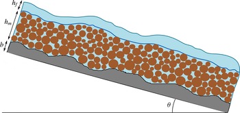
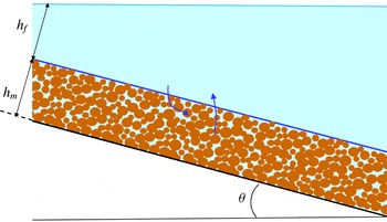
), see figure 1. The thickness of the mixture layer is denoted by
 $h_{m}$
, the thickness of the fluid-only layer by
 $h_{f}$
, and the fixed bottom is defined by a function
 $b$
.
Domain and geometrical parameters. The solid–fluid mixture lies between a fixed bottom and an upper pure fluid layer. The width
 $h_{m}$
of the mixture layer and the width
 $h_{f}$
of the pure fluid layer evolve with time.

The fluid velocity in the top layer is denoted by
 $\boldsymbol{u}_{f}$
, and in the mixture layer by
 $\boldsymbol{u}$
, while
 $\boldsymbol{v}$
denotes the velocity of the solid phase. For other terms, we will use as general notation the subscript
 $()_{s}$
for the solid phase,
 $()_{f_{m}}$
for the fluid in the mixture and just
 $()_{f}$
for the fluid-only layer.
Then, the solid equations (2.1a ), (2.9a ) are set in the mixture domain, while the fluid equations (2.1b ), (2.9b ) must hold within both domains. This yields for the fluid-only domain
 $$\begin{eqnarray}\displaystyle & \displaystyle \boldsymbol{{\rm\nabla}}\boldsymbol{\cdot }\boldsymbol{u}_{f}=0, & \displaystyle\end{eqnarray}$$
 $$\begin{eqnarray}\displaystyle & \displaystyle {\it\rho}_{f}(\partial _{t}\boldsymbol{u}_{f}+(\boldsymbol{u}_{f}\boldsymbol{\cdot }\boldsymbol{{\rm\nabla}})\boldsymbol{u}_{f})=-\boldsymbol{{\rm\nabla}}\boldsymbol{\cdot }\unicode[STIX]{x1D64F}_{f}+{\it\rho}_{f}\boldsymbol{g}, & \displaystyle\end{eqnarray}$$
 $$\begin{eqnarray}\partial _{t}\left({\it\rho}_{f}\frac{|\boldsymbol{u}_{f}|^{2}}{2}-{\it\rho}_{f}(\boldsymbol{g}\boldsymbol{\cdot }X)\right)+\boldsymbol{{\rm\nabla}}\boldsymbol{\cdot }\left({\it\rho}_{f}\frac{|\boldsymbol{u}_{f}|^{2}}{2}\boldsymbol{u}_{f}-{\it\rho}_{f}(\boldsymbol{g}\boldsymbol{\cdot }X)\boldsymbol{u}_{f}+\unicode[STIX]{x1D64F}_{f}\boldsymbol{u}_{f}\right)=\widetilde{\unicode[STIX]{x1D64F}_{f}}:\boldsymbol{{\rm\nabla}}\boldsymbol{u}_{f}.\end{eqnarray}$$
We can also consider that (2.1a
), (2.9a
) hold in the upper domain with the convention that there
 ${\it\varphi}=0$
and
 $\unicode[STIX]{x1D64F}_{s}=0$
. The closure equation (2.14) holds in the mixture domain.
The boundary conditions are taken as follows.
-
(i) At the bottom we consider the non-penetration conditions
(2.31a,b )where
$$\begin{eqnarray}\boldsymbol{u}\boldsymbol{\cdot }\boldsymbol{n}=0,\quad \boldsymbol{v}\boldsymbol{\cdot }\boldsymbol{n}=0\text{ at the bottom,}\end{eqnarray}$$
$\boldsymbol{n}$
is the upward space unit normal (i.e. the normal to the topography). This is completed with friction conditions. First, a solid Coulomb friction law is applied, (2.32)where
$$\begin{eqnarray}(\unicode[STIX]{x1D64F}_{s}\boldsymbol{n})_{{\it\tau}}=-\tan {\it\delta}_{eff}\,\text{sgn}(\boldsymbol{v})(\unicode[STIX]{x1D64F}_{s}\boldsymbol{n})\boldsymbol{\cdot }\boldsymbol{n}\quad \text{at the bottom},\end{eqnarray}$$
${\it\delta}_{eff}$
is the effective intergranular Coulomb friction angle from (2.20),
$\text{sgn}(\boldsymbol{v})=\boldsymbol{v}/|\boldsymbol{v}|$
, and the subscript
${\it\tau}$
denotes the tangential projection,
$\boldsymbol{v}_{{\it\tau}}=\boldsymbol{v}-(\boldsymbol{v}\boldsymbol{\cdot }\boldsymbol{n})\boldsymbol{n}$
for any vector
$\boldsymbol{v}$
. Unless not written explicitly here, a viscous friction term can also be added to (2.32), as is done for the numerical tests in § 5. Moreover, a generic Navier friction condition for the fluid phase is applied, (2.33)for some coefficient
$$\begin{eqnarray}(\unicode[STIX]{x1D64F}_{f_{m}}\,\boldsymbol{n})_{{\it\tau}}=-k_{b}\boldsymbol{u}\quad \text{at the bottom,}\end{eqnarray}$$
$k_{b}\geqslant 0$
. In particular, the choice
$k_{b}=0$
is possible for a slip condition. It seems irrelevant to consider a no-slip condition (
$k_{b}=\infty$
). A possibility is to take a Manning–Strickler law, for which
$k_{b}$
is proportional to
${\it\rho}_{f}|\boldsymbol{u}|$
. The choice of Iverson & George (Reference Iverson and George2014) is to take a viscous friction where
$k_{b}$
is proportional to
${\it\eta}_{f}/(h_{m}+h_{f})$
, with
${\it\eta}_{f}$
the viscosity of the fluid. One can think anyway that except for large times, the effects of fluid friction at the bottom are negligible with respect to the drag friction forces and the bottom Coulomb friction on the solid phase. It should be noted that any choice of friction boundary conditions for the fluid and solid phases at the bottom is formally possible in the model presented here. This choice will not affect our asymptotic analysis or the form of the limit averaged system.
-
(ii) At the free surface we assume no tension for the fluid,
(2.34)together with the kinematic condition
$$\begin{eqnarray}\unicode[STIX]{x1D64F}_{f}\boldsymbol{N}_{X}=0\quad \text{at the free surface},\end{eqnarray}$$
(2.35)where
$$\begin{eqnarray}N_{t}+\boldsymbol{u}_{f}\boldsymbol{\cdot }\boldsymbol{N}_{X}=0\quad \text{at the free surface},\end{eqnarray}$$
$\boldsymbol{N}=(N_{t},\boldsymbol{N}_{X})$
is a time–space normal to the free surface.
-
(iii) At the interface, we consider the kinematic condition for the solid phase,
(2.36)where we denote by
$$\begin{eqnarray}{\tilde{N}}_{t}+\boldsymbol{v}\boldsymbol{\cdot }\tilde{\boldsymbol{N}}_{X}=0\quad \text{at the interface,}\end{eqnarray}$$
$\tilde{\boldsymbol{N}}=({\tilde{N}}_{t},\tilde{\boldsymbol{N}}_{X})$
a time–space upward normal to the interface. Additional jump relations have to be prescribed. These relations state that the fluxes on both sides of the interface are related through transfer conditions. These are determined by global conservation properties, under the form of Rankine–Hugoniot conditions. We must first ensure that the total fluid mass is conserved. The Rankine–Hugoniot condition associated with (2.1b
), where
${\it\varphi}$
vanishes in the fluid-only region, leads to (2.37)where
$$\begin{eqnarray}{\tilde{N}}_{t}+\boldsymbol{u}_{f}\boldsymbol{\cdot }\tilde{\boldsymbol{N}}_{X}=(1-{\it\varphi}^{\ast })({\tilde{N}}_{t}+\boldsymbol{u}\boldsymbol{\cdot }\tilde{\boldsymbol{N}}_{X})\equiv \mathscr{V}_{f}\quad \text{at the interface},\end{eqnarray}$$
${\it\varphi}^{\ast }$
is the value of the solid volume fraction at the interface (the limit is taken from the mixture side). It should be noted that
${\it\varphi}$
is discontinuous at the interface. The term
$\mathscr{V}_{f}$
defines the fluid mass that is transferred from the mixture to the fluid-only layer (
$\mathscr{V}_{f}<0$
means that the fluid is transferred from the fluid-only region to the mixture region). The equation (2.37) says that the amount of fluid that is entering the fluid-only region is the same as the amount of fluid that leaves the mixture. This relation can also be written as (A 3). The conservation of total momentum gives (see appendix A) (2.38)The energy balance through the interface (see appendix A) yields the stress transfer condition
$$\begin{eqnarray}{\it\rho}_{f}\mathscr{V}_{f}(\boldsymbol{u}-\boldsymbol{u}_{f})+(\unicode[STIX]{x1D64F}_{s}+\unicode[STIX]{x1D64F}_{f_{m}})\tilde{\boldsymbol{N}}_{X}=\unicode[STIX]{x1D64F}_{f}\tilde{\boldsymbol{N}}_{X}\quad \text{at the interface}.\end{eqnarray}$$
(2.39)These conditions are completed by a Navier fluid friction condition
$$\begin{eqnarray}\displaystyle \displaystyle \unicode[STIX]{x1D64F}_{s}\tilde{\boldsymbol{N}}_{X} & = & \displaystyle \left(\frac{{\it\rho}_{f}}{2}\left((\boldsymbol{u}-\boldsymbol{u}_{f})\boldsymbol{\cdot }\frac{\tilde{\boldsymbol{N}}_{X}}{|\tilde{\boldsymbol{N}}_{X}|}\right)^{2}\right.\nonumber\\ \displaystyle & & \displaystyle +\left.\!\left((\unicode[STIX]{x1D64F}_{f_{m}}\tilde{\boldsymbol{N}}_{X})\boldsymbol{\cdot }\frac{\tilde{\boldsymbol{N}}_{X}}{|\tilde{\boldsymbol{N}}_{X}|^{2}}-p_{f_{m}}\right)\frac{{\it\varphi}^{\ast }}{1-{\it\varphi}^{\ast }}\right)\tilde{\boldsymbol{N}}_{X}\quad \text{at the interface}.\qquad\end{eqnarray}$$
(2.40)where
$$\begin{eqnarray}\left(\frac{\unicode[STIX]{x1D64F}_{f_{m}}+\unicode[STIX]{x1D64F}_{f}}{2}\tilde{\boldsymbol{N}}_{X}\right)_{{\it\tau}}=-k_{i}(\boldsymbol{u}_{f}-\boldsymbol{u})_{{\it\tau}}\quad \text{at the interface},\end{eqnarray}$$
$k_{i}\geqslant 0$
is a friction coefficient. This last condition is indeed a boundary friction for the upper fluid layer. Since this pure fluid layer is not affected by drag, the coefficient
$k_{i}$
cannot be neglected, and can be taken proportional to
${\it\rho}_{f}|(\boldsymbol{u}_{f}-\boldsymbol{u})_{{\it\tau}}|$
. It should be noted that since
${\it\varphi}^{\ast }\not =0$
and according to (2.37), one has in general
$(\boldsymbol{u}_{f}-\boldsymbol{u})\boldsymbol{\cdot }\tilde{\boldsymbol{N}}_{X}\not =0$
because of the fluid mass exchange through the interface. The no-slip condition
$(\boldsymbol{u}_{f}-\boldsymbol{u})_{{\it\tau}}=0$
(i.e.
$k_{i}=\infty$
) is of interest, and is indeed chosen in the simplified two-velocity model of § 4.3. More involved conditions are considered in Beavers & Joseph (Reference Beavers and Joseph1967).








3 Derivation of the thin-layer depth-averaged model
In this section we derive a depth-integrated thin-layer model from the Jackson model with the closure stated in § 2.
The geometrical setting is as follows. We have two layers, the one below being filled with the mixture of grains and fluid and the one above only with fluid (see figure 1). The equations of mass and momentum in the mixture region are given by (2.1a
), (2.1b
), (2.9a
) and (2.9b
), closed by the relation (2.14) with
 ${\it\Phi}$
defined by (2.19). The equations for the fluid-only layer are defined by (2.29a
), (2.29b
). The stress tensors for the solid and fluid phases in the mixture are given by (2.11). The boundary conditions are written in the previous subsection, as (2.31)–(2.40).
3.1 Local coordinates
We now write the equations in local coordinates. We use a decomposition of the velocities and the derivatives in their longitudinal and normal components. We denote by
 $\boldsymbol{x}=(x,y)$
a vector variable in a fixed plane inclined at angle
 ${\it\theta}$
,
 $x$
being in the direction of the slope, and by
 $z$
the variable normal to this plane (see figure 1). The equation of the bottom is thus given by
 $z=b(\boldsymbol{x})$
, the interface by
 $z=b(\boldsymbol{x})+h_{m}(t,\boldsymbol{x})$
and the free surface by
 $z=b(\boldsymbol{x})+h_{m}(t,\boldsymbol{x})+h_{f}(t,\boldsymbol{x})$
. The gravity vector is then
 $$\begin{eqnarray}\boldsymbol{g}=(-g\sin {\it\theta},0,-g\cos {\it\theta})^{t}\end{eqnarray}$$
(the slope angle
 ${\it\theta}$
is indeed negative in figure 1). The velocities are written as
 $\boldsymbol{u}_{f}=(\boldsymbol{u}_{f}^{\boldsymbol{x}},u_{f}^{z})$
,
 $\boldsymbol{u}_{f}^{\boldsymbol{x}}=(u_{f}^{x},u_{f}^{y})$
;
 $\boldsymbol{u}=(\boldsymbol{u}^{\boldsymbol{x}},u^{z})$
,
 $\boldsymbol{u}^{\boldsymbol{x}}=(u^{x},u^{y})$
;
 $\boldsymbol{v}=(\boldsymbol{v}^{\boldsymbol{x}},v^{z})$
,
 $\boldsymbol{v}^{\boldsymbol{x}}=(v^{x},v^{y})$
, and the gradient is
 $\boldsymbol{{\rm\nabla}}=(\boldsymbol{{\rm\nabla}}_{\boldsymbol{x}},\partial _{z})$
with
 $\boldsymbol{{\rm\nabla}}_{\boldsymbol{x}}=(\partial _{x},\partial _{y})$
. The equations can then be written as follows.
-
(i) In the mixture layer
$b<z<b+h_{m}$
: (3.2a )
$$\begin{eqnarray}\displaystyle & \displaystyle \partial _{t}{\it\varphi}+\boldsymbol{{\rm\nabla}}_{\boldsymbol{x}}\boldsymbol{\cdot }({\it\varphi}\boldsymbol{v}^{\boldsymbol{x}})+\partial _{z}({\it\varphi}v^{z})=0, & \displaystyle\end{eqnarray}$$
(3.2b )
$$\begin{eqnarray}\displaystyle & \displaystyle \partial _{t}(1-{\it\varphi})+\boldsymbol{{\rm\nabla}}_{\boldsymbol{x}}\boldsymbol{\cdot }((1-{\it\varphi})\boldsymbol{u}^{\boldsymbol{x}})+\partial _{z}((1-{\it\varphi})u^{z})=0, & \displaystyle\end{eqnarray}$$
(3.3a )
$$\begin{eqnarray}\displaystyle \displaystyle {\it\rho}_{s}{\it\varphi}(\partial _{t}\boldsymbol{v}^{\boldsymbol{x}}+\boldsymbol{v}^{\boldsymbol{x}}\boldsymbol{\cdot }\boldsymbol{{\rm\nabla}}_{\boldsymbol{x}}\boldsymbol{v}^{\boldsymbol{x}}+v^{z}\partial _{z}\boldsymbol{v}^{\boldsymbol{x}}) & = & \displaystyle -\boldsymbol{{\rm\nabla}}_{\boldsymbol{x}}\boldsymbol{\cdot }\unicode[STIX]{x1D64F}_{s}^{\boldsymbol{x}\boldsymbol{x}}-\partial _{z}\unicode[STIX]{x1D64F}_{s}^{\boldsymbol{x}z}-{\it\varphi}\boldsymbol{{\rm\nabla}}_{\boldsymbol{x}}p_{f_{m}}\nonumber\\ \displaystyle & & \displaystyle \displaystyle +\,\boldsymbol{f}_{\boldsymbol{x}}-{\it\varphi}{\it\rho}_{s}g\sin {\it\theta}(1,0)^{t},\end{eqnarray}$$
(3.3b )
$$\begin{eqnarray}\displaystyle \displaystyle {\it\rho}_{s}{\it\varphi}(\partial _{t}v^{z}+\boldsymbol{v}^{\boldsymbol{x}}\boldsymbol{\cdot }\boldsymbol{{\rm\nabla}}_{\boldsymbol{x}}v^{z}+v^{z}\partial _{z}v^{z}) & = & \displaystyle -\boldsymbol{{\rm\nabla}}_{\boldsymbol{x}}\boldsymbol{\cdot }\unicode[STIX]{x1D64F}_{s}^{\boldsymbol{x}z}-\partial _{z}\unicode[STIX]{x1D61B}_{s}^{zz}-{\it\varphi}\partial _{z}p_{f_{m}}\nonumber\\ \displaystyle & & \displaystyle \displaystyle +\,f_{z}-{\it\varphi}{\it\rho}_{s}g\cos {\it\theta},\end{eqnarray}$$
(3.4a )
$$\begin{eqnarray}\displaystyle \displaystyle {\it\rho}_{f}(1-{\it\varphi})(\partial _{t}\boldsymbol{u}^{\boldsymbol{x}}+\boldsymbol{u}^{\boldsymbol{x}}\boldsymbol{\cdot }\boldsymbol{{\rm\nabla}}_{\boldsymbol{x}}\boldsymbol{u}^{\boldsymbol{x}}+u^{z}\partial _{z}\boldsymbol{u}^{\boldsymbol{x}}) & = & \displaystyle -\boldsymbol{{\rm\nabla}}_{\boldsymbol{x}}\boldsymbol{\cdot }{\unicode[STIX]{x1D64F}_{f}}_{m}^{\boldsymbol{x}\boldsymbol{x}}-\partial _{z}{\unicode[STIX]{x1D64F}_{f}}_{m}^{\boldsymbol{x}\boldsymbol{z}}+{\it\varphi}\boldsymbol{{\rm\nabla}}_{\boldsymbol{x}}p_{f_{m}}\nonumber\\ \displaystyle & & \displaystyle \displaystyle -\,\boldsymbol{f}_{\boldsymbol{x}}-(1-{\it\varphi}){\it\rho}_{f}g\sin {\it\theta}(1,0)^{t},\qquad\end{eqnarray}$$
(3.4b )
$$\begin{eqnarray}\displaystyle \displaystyle {\it\rho}_{f}(1-{\it\varphi})(\partial _{t}u^{z}+\boldsymbol{u}^{\boldsymbol{x}}\boldsymbol{\cdot }\boldsymbol{{\rm\nabla}}_{\boldsymbol{x}}u^{z}+u^{z}\partial _{z}u^{z}) & = & \displaystyle -\boldsymbol{{\rm\nabla}}_{\boldsymbol{x}}\boldsymbol{\cdot }{\unicode[STIX]{x1D64F}_{f}}_{m}^{\boldsymbol{x}\boldsymbol{z}}-\partial _{z}{\unicode[STIX]{x1D61B}_{f}}_{m}^{zz}+{\it\varphi}\partial _{z}p_{f_{m}}\qquad \nonumber\\ \displaystyle & & \displaystyle \displaystyle -\,f_{z}-(1-{\it\varphi}){\it\rho}_{f}g\cos {\it\theta},\end{eqnarray}$$
(3.5)
$$\begin{eqnarray}\boldsymbol{{\rm\nabla}}_{\boldsymbol{x}}\boldsymbol{\cdot }\boldsymbol{v}^{\boldsymbol{x}}+\partial _{z}v^{z}={\it\Phi}.\end{eqnarray}$$
-
(ii) In the fluid-only layer
$b+h_{m}<z<b+h_{m}+h_{f}$
: (3.6)
$$\begin{eqnarray}\boldsymbol{{\rm\nabla}}_{\boldsymbol{x}}\boldsymbol{\cdot }\boldsymbol{u}_{f}^{\boldsymbol{x}}+\partial _{z}u_{f}^{z}=0,\end{eqnarray}$$
(3.7a )
$$\begin{eqnarray}\displaystyle & \displaystyle {\it\rho}_{f}(\partial _{t}\boldsymbol{u}_{f}^{\boldsymbol{x}}+\boldsymbol{u}_{f}^{\boldsymbol{x}}\boldsymbol{\cdot }\boldsymbol{{\rm\nabla}}_{\boldsymbol{x}}\boldsymbol{u}_{f}^{\boldsymbol{x}}+u_{f}^{z}\partial _{z}\boldsymbol{u}_{f}^{\boldsymbol{x}})=-\boldsymbol{{\rm\nabla}}_{\boldsymbol{x}}\boldsymbol{\cdot }\unicode[STIX]{x1D64F}_{f}^{\boldsymbol{x}\boldsymbol{x}}-\partial _{z}\unicode[STIX]{x1D64F}_{f}^{\boldsymbol{x}z}-{\it\rho}_{f}g\sin {\it\theta}(1,0)^{t}, & \displaystyle\end{eqnarray}$$
(3.7b )
$$\begin{eqnarray}\displaystyle & \displaystyle {\it\rho}_{f}(\partial _{t}u_{f}^{z}+\boldsymbol{u}_{f}^{\boldsymbol{x}}\boldsymbol{\cdot }\boldsymbol{{\rm\nabla}}_{\boldsymbol{x}}u_{f}^{z}+u_{f}^{z}\partial _{z}u_{f}^{z})=-\boldsymbol{{\rm\nabla}}_{\boldsymbol{x}}\boldsymbol{\cdot }\unicode[STIX]{x1D64F}_{f}^{\boldsymbol{x}z}-\partial _{z}\unicode[STIX]{x1D61B}_{f}^{zz}-{\it\rho}_{f}g\cos {\it\theta}. & \displaystyle\end{eqnarray}$$





The boundary conditions can be written as follows.
-
(i) At the bottom
$z=b$
, with
$\boldsymbol{n}=(-\boldsymbol{{\rm\nabla}}_{\boldsymbol{x}}b,1)/\sqrt{1+|\boldsymbol{{\rm\nabla}}_{\boldsymbol{x}}b|^{2}}$
.-
(1) Non-penetration condition for each phase:
(3.8)
$$\begin{eqnarray}\boldsymbol{v}^{\boldsymbol{x}}\boldsymbol{\cdot }\boldsymbol{{\rm\nabla}}_{\boldsymbol{ x}}b=v^{z}\quad \text{at }z=b,\end{eqnarray}$$
(3.9)
$$\begin{eqnarray}\boldsymbol{u}^{\boldsymbol{x}}\boldsymbol{\cdot }\boldsymbol{{\rm\nabla}}_{\boldsymbol{ x}}b=u^{z}\quad \text{at }z=b.\end{eqnarray}$$
-
(2) Coulomb friction law:
(3.10)with
$$\begin{eqnarray}\frac{\unicode[STIX]{x1D64F}_{s}^{\boldsymbol{x}z}-\unicode[STIX]{x1D64F}_{s}^{\boldsymbol{x}\boldsymbol{x}}\boldsymbol{{\rm\nabla}}_{\boldsymbol{x}}b+\boldsymbol{{\rm\nabla}}_{\boldsymbol{x}}b\,(\unicode[STIX]{x1D64F}_{s}\boldsymbol{n})\boldsymbol{\cdot }\boldsymbol{n}}{\sqrt{1+|\boldsymbol{{\rm\nabla}}_{\boldsymbol{x}}b|^{2}}}=-\tan {\it\delta}_{eff}\frac{\boldsymbol{v}^{\boldsymbol{x}}}{\sqrt{|\boldsymbol{v}^{\boldsymbol{x}}|^{2}+(v^{z})^{2}}}(\unicode[STIX]{x1D64F}_{s}\boldsymbol{n})\boldsymbol{\cdot }\boldsymbol{n}\quad \text{at }z=b,\end{eqnarray}$$
(3.11)
$$\begin{eqnarray}(\unicode[STIX]{x1D64F}_{s}\boldsymbol{n})\boldsymbol{\cdot }\boldsymbol{n}=\frac{(\unicode[STIX]{x1D64F}_{s}^{\boldsymbol{x}\boldsymbol{x}}\boldsymbol{{\rm\nabla}}_{\boldsymbol{x}}b)\boldsymbol{\cdot }\boldsymbol{{\rm\nabla}}_{\boldsymbol{x}}b-2\unicode[STIX]{x1D64F}_{s}^{\boldsymbol{x}z}\boldsymbol{\cdot }\boldsymbol{{\rm\nabla}}_{\boldsymbol{x}}b+\unicode[STIX]{x1D61B}_{s}^{zz}}{1+|\boldsymbol{{\rm\nabla}}_{\boldsymbol{x}}b|^{2}}.\end{eqnarray}$$
-
(3) Navier friction condition for the fluid phase:
(3.12)
$$\begin{eqnarray}\frac{{\unicode[STIX]{x1D64F}_{f}}_{m}^{\boldsymbol{x}\boldsymbol{z}}-{\unicode[STIX]{x1D64F}_{f}}_{m}^{\boldsymbol{x}\boldsymbol{x}}\boldsymbol{{\rm\nabla}}_{\boldsymbol{x}}b+\boldsymbol{{\rm\nabla}}_{\boldsymbol{x}}b\,(\unicode[STIX]{x1D64F}_{f_{m}}\boldsymbol{n})\boldsymbol{\cdot }\boldsymbol{n}}{\sqrt{1+|\boldsymbol{{\rm\nabla}}_{\boldsymbol{x}}b|^{2}}}=-k_{b}\boldsymbol{u}^{\boldsymbol{x}}\quad \text{at }z=b.\end{eqnarray}$$
-
-
(ii) At the free surface
$z=b+h_{m}+h_{f}$
, with
$\boldsymbol{N}_{X}=(-\boldsymbol{{\rm\nabla}}_{\boldsymbol{x}}(b+h_{m}+h_{f}),1)$
,
$N_{t}=-\partial _{t}(b+h_{m}+h_{f})$
.-
(1) Stress free condition:
(3.13)
$$\begin{eqnarray}\displaystyle -\unicode[STIX]{x1D64F}_{f}^{\boldsymbol{x}\boldsymbol{x}}\boldsymbol{{\rm\nabla}}_{\boldsymbol{x}}(b+h_{m}+h_{f})+\unicode[STIX]{x1D64F}_{f}^{\boldsymbol{x}z}=0\quad \text{at }z=b+h_{m}+h_{f}, & & \displaystyle\end{eqnarray}$$
(3.14)
$$\begin{eqnarray}\displaystyle -\unicode[STIX]{x1D64F}_{f}^{\boldsymbol{x}z}\boldsymbol{\cdot }\boldsymbol{{\rm\nabla}}_{\boldsymbol{x}}(b+h_{m}+h_{f})+\unicode[STIX]{x1D61B}_{f}^{zz}=0\quad \text{at }z=b+h_{m}+h_{f}. & & \displaystyle\end{eqnarray}$$
-
(2) Kinematic condition:
(3.15)
$$\begin{eqnarray}\partial _{t}(h_{m}+h_{f})+\boldsymbol{u}_{f}^{\boldsymbol{x}}\boldsymbol{\cdot }\boldsymbol{{\rm\nabla}}_{\boldsymbol{ x}}(b+h_{m}+h_{f})=u_{f}^{z}\quad \text{at }z=b+h_{m}+h_{f}.\end{eqnarray}$$
-
-
(iii) At the interface
$z=b+h_{m}$
, with
$\tilde{\boldsymbol{N}}_{X}=(-\boldsymbol{{\rm\nabla}}_{\boldsymbol{x}}(b+h_{m}),1)$
,
${\tilde{N}}_{t}=-\partial _{t}(b+h_{m})$
.-
(1) Kinematic condition:
(3.16)
$$\begin{eqnarray}\partial _{t}h_{m}+\boldsymbol{v}^{\boldsymbol{x}}\boldsymbol{\cdot }\boldsymbol{{\rm\nabla}}_{\boldsymbol{ x}}(b+h_{m})=v^{z}\quad \text{at }z=b+h_{m}.\end{eqnarray}$$
-
(2) Conservation of fluid mass:
(3.17)
$$\begin{eqnarray}\displaystyle & & \displaystyle \displaystyle \partial _{t}h_{m}+\boldsymbol{u}_{f}^{\boldsymbol{x}}\boldsymbol{\cdot }\boldsymbol{{\rm\nabla}}_{\boldsymbol{x}}(b+h_{m})-u_{f}^{z}=(1-{\it\varphi}^{\ast })(\partial _{t}h_{m}+\boldsymbol{u}^{\boldsymbol{x}}\boldsymbol{\cdot }\boldsymbol{{\rm\nabla}}_{\boldsymbol{x}}(b+h_{m})-u^{z})\equiv -\mathscr{V}_{f}\nonumber\\ \displaystyle & & \displaystyle \quad \text{at }z=b+h_{m}.\end{eqnarray}$$
-
(3) Conservation of total momentum:
(3.18)
$$\begin{eqnarray}{\it\rho}_{f}\mathscr{V}_{f}(\boldsymbol{u}^{\boldsymbol{x}}-\boldsymbol{u}_{f}^{\boldsymbol{x}})-(\unicode[STIX]{x1D64F}_{s}^{\boldsymbol{x}\boldsymbol{x}}+{\unicode[STIX]{x1D64F}_{f}}_{m}^{\boldsymbol{x}\boldsymbol{x}}-\unicode[STIX]{x1D64F}_{f}^{\boldsymbol{x}\boldsymbol{x}})\boldsymbol{{\rm\nabla}}_{\boldsymbol{ x}}(b+h_{m})+\unicode[STIX]{x1D64F}_{s}^{\boldsymbol{x}z}+{\unicode[STIX]{x1D64F}_{f}}_{m}^{\boldsymbol{x}\boldsymbol{z}}-\unicode[STIX]{x1D64F}_{f}^{\boldsymbol{x}z}=0,\end{eqnarray}$$
(3.19)at
$$\begin{eqnarray}{\it\rho}_{f}\mathscr{V}_{f}(u^{z}-u_{f}^{z})-(\unicode[STIX]{x1D64F}_{s}^{\boldsymbol{x}z}+{\unicode[STIX]{x1D64F}_{f}}_{m}^{\boldsymbol{x}\boldsymbol{z}}-\unicode[STIX]{x1D64F}_{f}^{\boldsymbol{x}z})\boldsymbol{\cdot }\boldsymbol{{\rm\nabla}}_{\boldsymbol{ x}}(b+h_{m})+\unicode[STIX]{x1D61B}_{s}^{zz}+{\unicode[STIX]{x1D61B}_{f}}_{m}^{zz}-\unicode[STIX]{x1D61B}_{f}^{zz}=0\end{eqnarray}$$
$z=b+h_{m}$
.
-
(4) Stress transfer:
with(3.20a )
$$\begin{eqnarray}\displaystyle & \displaystyle -\unicode[STIX]{x1D64F}_{s}^{\boldsymbol{x}\boldsymbol{x}}\boldsymbol{{\rm\nabla}}_{\boldsymbol{x}}(b+h_{m})+\unicode[STIX]{x1D64F}_{s}^{\boldsymbol{x}z}=-p_{s}^{\ast }\boldsymbol{{\rm\nabla}}_{\boldsymbol{x}}(b+h_{m})\quad \text{at }z=b+h_{m}, & \displaystyle\end{eqnarray}$$
(3.20b )
$$\begin{eqnarray}\displaystyle & \displaystyle -\unicode[STIX]{x1D64F}_{s}^{\boldsymbol{x}z}\boldsymbol{\cdot }\boldsymbol{{\rm\nabla}}_{\boldsymbol{x}}(b+h_{m})+\unicode[STIX]{x1D61B}_{s}^{zz}=p_{s}^{\ast }\quad \text{at }z=b+h_{m}, & \displaystyle\end{eqnarray}$$
(3.21)
$$\begin{eqnarray}\displaystyle \displaystyle p_{s}^{\ast } & = & \displaystyle \frac{{\it\rho}_{f}}{2}\frac{1}{1+|\boldsymbol{{\rm\nabla}}_{\boldsymbol{x}}(b+h_{m})|^{2}}(u^{z}-u_{f}^{z}-(\boldsymbol{u}^{\boldsymbol{x}}-\boldsymbol{u}_{f}^{\boldsymbol{x}})\boldsymbol{\cdot }\boldsymbol{{\rm\nabla}}_{\boldsymbol{x}}(b+h_{m}))^{2}+\frac{{\it\varphi}^{\ast }}{1-{\it\varphi}^{\ast }}\nonumber\\ \displaystyle & & \displaystyle \displaystyle \times \left(\frac{({\unicode[STIX]{x1D64F}_{f}}_{m}^{\boldsymbol{x}\boldsymbol{x}}\boldsymbol{{\rm\nabla}}_{\boldsymbol{ x}}(b+h_{m}))\boldsymbol{\cdot }\boldsymbol{{\rm\nabla}}_{\boldsymbol{x}}(b+h_{m})-2{\unicode[STIX]{x1D64F}_{f}}_{m}^{\boldsymbol{x}\boldsymbol{z}}\boldsymbol{\cdot }\boldsymbol{{\rm\nabla}}_{\boldsymbol{ x}}(b+h_{m})+{\unicode[STIX]{x1D61B}_{f}}_{m}^{zz}}{1+|\boldsymbol{{\rm\nabla}}_{\boldsymbol{x}}(b+h_{m})|^{2}}-p_{f_{m}}\right)\!.\nonumber\\ \displaystyle & & \displaystyle\end{eqnarray}$$
-
(5) Navier fluid friction:
(3.22)
$$\begin{eqnarray}\displaystyle & & \displaystyle \displaystyle {\unicode[STIX]{x1D64F}_{f}}_{m}^{\boldsymbol{x}\boldsymbol{z}}+\unicode[STIX]{x1D64F}_{f}^{\boldsymbol{x}z}-({\unicode[STIX]{x1D64F}_{f}}_{m}^{\boldsymbol{x}\boldsymbol{x}}+\unicode[STIX]{x1D64F}_{f}^{\boldsymbol{x}\boldsymbol{x}})\boldsymbol{{\rm\nabla}}_{\boldsymbol{x}}(b+h_{m})\nonumber\\ \displaystyle & & \displaystyle \displaystyle \qquad +\,\boldsymbol{{\rm\nabla}}_{\boldsymbol{x}}(b+h_{m})((({\unicode[STIX]{x1D64F}_{f}}_{m}^{\boldsymbol{x}\boldsymbol{x}}+\unicode[STIX]{x1D64F}_{f}^{\boldsymbol{x}\boldsymbol{x}})\boldsymbol{{\rm\nabla}}_{\boldsymbol{x}}(b+h_{m}))\boldsymbol{\cdot }\boldsymbol{{\rm\nabla}}_{\boldsymbol{x}}(b+h_{m})\nonumber\\ \displaystyle & & \displaystyle \displaystyle \qquad -\,2({\unicode[STIX]{x1D64F}_{f}}_{m}^{\boldsymbol{x}\boldsymbol{z}}+\unicode[STIX]{x1D64F}_{f}^{\boldsymbol{x}z})\boldsymbol{\cdot }\boldsymbol{{\rm\nabla}}_{\boldsymbol{x}}(b+h_{m})+{\unicode[STIX]{x1D61B}_{f}}_{m}^{zz}+\unicode[STIX]{x1D61B}_{f}^{zz} )/(1+|\boldsymbol{{\rm\nabla}}_{\boldsymbol{x}}(b+h_{m})|^{2})\nonumber\\ \displaystyle & & \displaystyle \quad \displaystyle =-2k_{i}\left(\boldsymbol{u}_{f}^{\boldsymbol{x}}-\boldsymbol{u}^{\boldsymbol{x}}+\boldsymbol{{\rm\nabla}}_{\boldsymbol{x}}(b+h_{m})\frac{u_{f}^{z}-u^{z}-(\boldsymbol{u}_{f}^{\boldsymbol{x}}-\boldsymbol{u}^{\boldsymbol{x}})\boldsymbol{\cdot }\boldsymbol{{\rm\nabla}}_{\boldsymbol{ x}}(b+h_{m})}{1+|\boldsymbol{{\rm\nabla}}_{\boldsymbol{x}}(b+h_{m})|^{2}}\right)\nonumber\\ \displaystyle & & \displaystyle \qquad \quad \quad \text{ at }z=b+h_{m}.\end{eqnarray}$$
-












3.2 Averaged mass equations
In order to get the averaged solid mass equation, we integrate (3.2a
) with respect to
 $z$
in the mixture layer
 $b<z<b+h_{m}$
. Using (3.8) and (3.16) we obtain
 $$\begin{eqnarray}\partial _{t}\int _{b}^{b+h_{m}}{\it\varphi}\,\text{d}z+\boldsymbol{{\rm\nabla}}_{\boldsymbol{x}}\boldsymbol{\cdot }\int _{b}^{b+h_{m}}{\it\varphi}\boldsymbol{v}^{\boldsymbol{x}}\,\text{d}z=0.\end{eqnarray}$$
Similarly, the fluid averaged mass equation in the mixture is obtained by integrating (3.2b
) for
 $b<z<b+h_{m}$
. According to (3.9) and (3.17) it gives
 $$\begin{eqnarray}\partial _{t}\int _{b}^{b+h_{m}}(1-{\it\varphi})\,\text{d}z+\boldsymbol{{\rm\nabla}}_{\boldsymbol{x}}\boldsymbol{\cdot }\int _{b}^{b+h_{m}}(1-{\it\varphi})\boldsymbol{u}^{\boldsymbol{x}}\,\text{d}z=-\mathscr{V}_{f}.\end{eqnarray}$$
Finally, the fluid averaged mass equation in the fluid-only layer is obtained by integrating (3.6) for
 $b+h_{m}<z<b+h_{m}+h_{f}$
together with the conditions (3.15) and (3.17). It yields
 $$\begin{eqnarray}\partial _{t}h_{f}+\boldsymbol{{\rm\nabla}}_{\boldsymbol{x}}\boldsymbol{\cdot }\int _{b+h_{m}}^{b+h_{m}+h_{f}}\boldsymbol{u}_{f}^{\boldsymbol{x}}\,\text{d}z=\mathscr{V}_{f}.\end{eqnarray}$$
The sum of (3.24) and (3.25) indeed gives the total fluid mass conservation.
3.3 Asymptotic hypothesis
We introduce the characteristic width and length of the domain,
 $H$
and
 $L$
respectively, and the aspect ratio
 ${\it\epsilon}=H/L$
, supposed to be small in agreement with the thin-layer framework. Then, we assume the following asymptotic scales in terms of
 ${\it\epsilon}$
:
 $$\begin{eqnarray}\displaystyle \hspace{-20.00003pt}\left.\begin{array}{@{}c@{}}\displaystyle h_{m}\sim {\it\epsilon},\quad h_{f}\sim {\it\epsilon},\quad \boldsymbol{{\rm\nabla}}_{\boldsymbol{x}}b=\mathit{O}({\it\epsilon}),\quad \unicode[STIX]{x1D64F}_{s}=\mathit{O}({\it\epsilon}),\quad \unicode[STIX]{x1D64F}_{f_{m}}=\mathit{O}({\it\epsilon}),\quad \unicode[STIX]{x1D64F}_{f}=\mathit{O}({\it\epsilon}),\\ \displaystyle \boldsymbol{v}^{\boldsymbol{x}}=\mathit{O}(1),\quad \boldsymbol{u}^{\boldsymbol{x}}=\mathit{O}(1),\quad \boldsymbol{u}_{f}^{\boldsymbol{x}}=\mathit{O}(1),\quad {\it\varphi}=\mathit{O}(1),\quad {\it\Phi}=\mathit{O}(1),\\ \displaystyle k_{b}=\mathit{O}({\it\epsilon}),\quad k_{i}=\mathit{O}({\it\epsilon}).\end{array}\right\} & & \displaystyle\end{eqnarray}$$
These orders of magnitude indeed have to be expressed in the natural units of each quantity. Taking
 $L$
as the typical length unit,
 ${\it\tau}=\sqrt{L/g}$
as the typical time unit, all of these natural units can be expressed in terms of
 $L$
,
 ${\it\tau}$
and
 ${\it\rho}_{s}$
(or
 ${\it\rho}_{f}$
, which is assumed to be of the same order of magnitude as
 ${\it\rho}_{s}$
). We assume that the unknowns vary at the scales
 $L$
in the downslope direction,
 ${\it\epsilon}L$
in the normal direction and
 ${\it\tau}$
in time, which means formally that
 $\boldsymbol{{\rm\nabla}}_{\boldsymbol{x}}=\mathit{O}(1),\partial _{z}=\mathit{O}({\it\epsilon}^{-1}),\partial _{t}=\mathit{O}(1)$
.
These scaling assumptions deserve some comments. First, the scaling in the downslope direction means that we are describing the observable phenomenon at the typical scale
 $L$
where the collective phenomena take place, this scale being much larger than the size of the grains. Second, the scaling in the normal direction means that there could be normal variations at the scale of the layer. Third, the time scale
 ${\it\tau}$
that is used is the one at which gravity comes into play. This means that we are describing transient flows typical in avalanche dynamics, which occur, for example, when an initial mass at rest is entrained by gravity. Indeed, in natural avalanche flows the events never last longer than a few
 ${\it\tau}$
. Moreover, even for larger times that can be relevant in laboratory experiments, shallow water type averaged equations are commonly used to describe well-established almost steady flows for which gravity balances viscoplastic effects. Thus, our final set of equations will be relevant also in this situation.
Then, equation (3.25) implies that
 $\mathscr{V}_{f}=\mathit{O}({\it\epsilon})$
. As in Bouchut et al. (Reference Bouchut, Mangeney-Castelnau, Perthame and Vilotte2003) and Bouchut & Westdickenberg (Reference Bouchut and Westdickenberg2004) we shall assume that the tangential velocities and the solid volume fraction do not depend on
 $z$
up to errors in
 $\mathit{O}({\it\epsilon}^{2})$
,
 $$\begin{eqnarray}\displaystyle & \displaystyle \boldsymbol{v}^{\boldsymbol{x}}=\overline{\boldsymbol{v}^{\boldsymbol{x}}}(t,\boldsymbol{x})+\mathit{O}({\it\epsilon}^{2}), & \displaystyle\end{eqnarray}$$
 $$\begin{eqnarray}\displaystyle & \displaystyle \boldsymbol{u}^{\boldsymbol{x}}=\overline{\boldsymbol{u}^{\boldsymbol{x}}}(t,\boldsymbol{x})+\mathit{O}({\it\epsilon}^{2}), & \displaystyle\end{eqnarray}$$
 $$\begin{eqnarray}\displaystyle & \displaystyle \boldsymbol{u}_{f}^{\boldsymbol{x}}=\overline{\boldsymbol{u}_{f}^{\boldsymbol{x}}}(t,\boldsymbol{x})+\mathit{O}({\it\epsilon}^{2}), & \displaystyle\end{eqnarray}$$
 $$\begin{eqnarray}\displaystyle & \displaystyle {\it\varphi}=\bar{{\it\varphi}}(t,\boldsymbol{x})+\mathit{O}({\it\epsilon}^{2}). & \displaystyle\end{eqnarray}$$
Then, from (3.5) and the boundary condition (3.8) we get that
 $v^{z}=\mathit{O}({\it\epsilon})$
. Similarly, from (3.2b
) and (3.9) we get
 $(1-{\it\varphi})u^{z}=\mathit{O}({\it\epsilon})$
, thus
 $u^{z}=\mathit{O}({\it\epsilon})$
. Finally, from (3.6) and (3.17) we obtain
 $u_{f}^{z}=\mathit{O}({\it\epsilon})$
. We assume also for the closure function (2.19) an expansion as
 $$\begin{eqnarray}{\it\Phi}=\bar{{\it\Phi}}(t,\boldsymbol{x})+\mathit{O}({\it\epsilon}^{2}),\end{eqnarray}$$
with
 $$\begin{eqnarray}\bar{{\it\Phi}}=K\bar{\dot{{\it\gamma}}}(\bar{{\it\varphi}}-\bar{{\it\varphi}}_{c}^{eq}).\end{eqnarray}$$
We adopt this approximation in order to make the derivation possible, even if it looks to not be appropriate because of the dependence on the pressure of
 ${\it\varphi}_{c}^{eq}$
, and of the nonlinear coupling of
 $\dot{{\it\gamma}}$
. Without (3.31), one should analyse the dependence in
 $z$
of
 ${\it\varphi}$
and
 ${\it\Phi}$
, as done in Morales de Luna (Reference Morales de Luna2008) in the dry case. The values for
 $\bar{\dot{{\it\gamma}}}$
and
 $\bar{{\it\varphi}}_{c}^{eq}$
are discussed in § 4.6. Then, using the closure equation (3.5), the equation (3.2a
) for
 ${\it\varphi}$
gives
 $$\begin{eqnarray}\partial _{t}\bar{{\it\varphi}}+\overline{\boldsymbol{v}^{\boldsymbol{x}}}\boldsymbol{\cdot }\boldsymbol{{\rm\nabla}}_{\boldsymbol{x}}\bar{{\it\varphi}}=-\bar{{\it\varphi}}\bar{{\it\Phi}}+\mathit{O}({\it\epsilon}^{2}).\end{eqnarray}$$
Regarding the stress tensors
 $\unicode[STIX]{x1D64F}_{k}$
(
 $k=s,f_{m},f$
), they are decomposed as
 $$\begin{eqnarray}\unicode[STIX]{x1D64F}_{k}=p_{k}\text{Id}+\widetilde{\unicode[STIX]{x1D64F}}_{k},\end{eqnarray}$$
and suitable rheological assumptions should be made to define
 $\widetilde{\unicode[STIX]{x1D64F}}_{k}$
. A general approach has been proposed in Bouchut & Boyaval (Reference Bouchut and Boyaval2016) to deal with velocity profiles in the thin-layer asymptotics and in the case of Newtonian or non-Newtonian rheologies. Here, as in Bouchut & Westdickenberg (Reference Bouchut and Westdickenberg2004), since we aim to represent only depth-averaged effects, we prefer to simplify the rheologies and replace the effect of the stress tensors inside the domain by boundary layers due to the friction conditions, namely (3.10), (3.12), (3.22), and also due to the momentum conservation (3.18), while we neglect viscous effects. Thus, we shall assume that the stresses
 $\widetilde{\unicode[STIX]{x1D64F}}_{k}$
are
 $\mathit{O}({\it\epsilon}^{2})$
far from the boundaries
 $z=b,b+h_{m}$
and can just be non-zero close to these boundaries. Indeed, because of the particular form of (3.10), (3.12), (3.22), (3.18), we assume that
 $$\begin{eqnarray}\left.\begin{array}{@{}rl@{}}\displaystyle \widetilde{\unicode[STIX]{x1D64F}}_{s}^{\boldsymbol{x}z},\widetilde{\unicode[STIX]{x1D64F}}_{f_{m}}^{\boldsymbol{x}z},\widetilde{\unicode[STIX]{x1D64F}}_{f}^{\boldsymbol{x}z} & \displaystyle \text{can be }\mathit{O}({\it\epsilon})\text{ close to the boundaries }z=b,b+h_{m},\\ & \displaystyle \text{but are }\mathit{O}({\it\epsilon}^{2})\text{ far from these boundaries},\end{array}\right\}\end{eqnarray}$$
while the other components satisfy
 $$\begin{eqnarray}\widetilde{\unicode[STIX]{x1D64F}}_{k}^{\boldsymbol{x}\boldsymbol{x}}=\widetilde{\unicode[STIX]{x1D61B}}_{k}^{zz}=\mathit{O}({\it\epsilon}^{2})\quad \text{everywhere}.\end{eqnarray}$$
Regarding the drag term defined in (2.7), we have according to (2.8)
 $$\begin{eqnarray}\tilde{{\it\beta}}=\bar{{\it\beta}}(t,\boldsymbol{x})(1+\mathit{O}({\it\epsilon}^{2})),\end{eqnarray}$$
with
 $$\begin{eqnarray}\bar{{\it\beta}}=(1-\bar{{\it\varphi}})^{2}\frac{{\it\eta}_{f}}{\bar{{\it\kappa}}}.\end{eqnarray}$$
We shall consider two possible sets of assumptions.
-
(i) The drag term is quite strong, that is
(3.39)Then, since the drag force
$$\begin{eqnarray}\bar{{\it\beta}}\sim {\it\epsilon}^{-1}.\end{eqnarray}$$
$\tilde{{\it\beta}}(\boldsymbol{u}-\boldsymbol{v})$
has to balance gravity terms, it necessarily remains bounded. This implies that after an eventual initial layer (i.e. a short time interval during which the initial value of
$\boldsymbol{u}^{\boldsymbol{x}}-\boldsymbol{v}^{\boldsymbol{x}}$
is damped), one has (3.40)
$$\begin{eqnarray}\boldsymbol{u}^{\boldsymbol{x}}-\boldsymbol{v}^{\boldsymbol{x}}=\mathit{O}({\it\epsilon}).\end{eqnarray}$$
-
(ii) The drag term is moderate, that is
(3.41)In this case one has just
$$\begin{eqnarray}\bar{{\it\beta}}=\mathit{O}(1).\end{eqnarray}$$
$\boldsymbol{u}^{\boldsymbol{x}}-\boldsymbol{v}^{\boldsymbol{x}}=\mathit{O}(1)$
, according to (3.26).


It should be noted that in both cases one has
 $\bar{{\it\beta}}(\boldsymbol{u}^{\boldsymbol{x}}-\boldsymbol{v}^{\boldsymbol{x}})=\mathit{O}(1)$
. The relevance of the assumptions (3.39) or (3.41) can be evaluated as follows. According to (2.9a
), the effective drag friction coefficient for the solid phase is
 $\tilde{{\it\beta}}/{\it\rho}_{s}{\it\varphi}$
. The assumption (3.39) or (3.41) has to be evaluated in the corresponding unit, which means that we must evaluate the dimensionless number
 $\bar{{\it\beta}}{\it\tau}/{\it\rho}_{s}\bar{{\it\varphi}}$
, with
 ${\it\tau}=\sqrt{L/g}$
the reference time unit (see above). We compute using (3.38)
 $$\begin{eqnarray}\frac{\bar{{\it\beta}}{\it\tau}}{{\it\rho}_{s}\bar{{\it\varphi}}}=\frac{(1-\bar{{\it\varphi}})^{2}}{\bar{{\it\varphi}}}\frac{{\it\eta}_{f}{\it\tau}}{{\it\rho}_{s}\bar{{\it\kappa}}}.\end{eqnarray}$$
We consider the values
 $g=9.81~\text{m}~\text{s}^{-2}$
,
 ${\it\rho}_{s}=2500~\text{kg}~\text{m}^{-3}$
. In the typical laboratory experimental context we can take as in Pailha & Pouliquen (Reference Pailha and Pouliquen2009)
 $\bar{{\it\kappa}}=d^{2}(1-\bar{{\it\varphi}})^{3}/(150\bar{{\it\varphi}}^{2})$
, with
 $d$
the diameter of the (spherical) grains. The typical values
 $d=5\times 10^{-4}~\text{m}$
,
 $L\approx 0.2~\text{m}$
,
 $\bar{{\it\varphi}}/(1-\bar{{\it\varphi}})\approx 1$
with
 ${\it\eta}_{f}=10^{-3}~\text{Pa}~\text{s}$
for water give a slightly strong dimensionless drag coefficient
 $\bar{{\it\beta}}{\it\tau}/{\it\rho}_{s}\bar{{\it\varphi}}\approx 34$
. For natural landslides or large-scale US Geological Survey debris flows (Iverson et al.
Reference Iverson, Logan, LaHusen and Berti2010), one can take as in Iverson & George (Reference Iverson and George2014) a grain-size variability empirical formula
 $\bar{{\it\kappa}}={\it\kappa}_{0}\exp ((0.6-\bar{{\it\varphi}})/0.04)$
with
 ${\it\kappa}_{0}\approx 10^{-11}~\text{m}^{2}$
. We choose
 $L\approx 20~\text{m}$
,
 ${\it\eta}_{f}=10^{-2}~\text{Pa}~\text{s}$
for muddy water,
 $\bar{{\it\varphi}}\approx 0.5$
, which gives a very strong dimensionless drag coefficient,
 $\bar{{\it\beta}}{\it\tau}/{\it\rho}_{s}\bar{{\it\varphi}}\approx 2\times 10^{4}$
.
We conclude that the assumption (3.39) is valid in the natural context, while (3.41) is more valid in the experimental context. However, equation (3.41) could be valid also in the natural context if the permeability is higher,
 ${\it\kappa}_{0}\approx 10^{-7}~\text{m}^{2}$
for highly mobile flows (Iverson & George Reference Iverson and George2014).
3.4 Averaged momentum equations
In order to get the averaged momentum equations, we have first to get expressions for the pressures. Computations shown in appendix B give the fluid pressure in the fluid-only layer,
 $$\begin{eqnarray}p_{f}={\it\rho}_{f}g\cos {\it\theta}(b+h_{m}+h_{f}-z)+\mathit{O}({\it\epsilon}^{2})\quad \text{for }b+h_{m}<z<b+h_{m}+h_{f},\end{eqnarray}$$
and in the mixture layer,
 $$\begin{eqnarray}\displaystyle p_{f_{m}}={\it\rho}_{f}g\cos {\it\theta}(b+h_{m}+h_{f}-z)+p_{f_{m}}^{e}+\mathit{O}({\it\epsilon}^{2})\quad \text{for }b<z<b+h_{m},\end{eqnarray}$$
where
 $$\begin{eqnarray}p_{f_{m}}^{e}\equiv \frac{\bar{{\it\beta}}}{1-\bar{{\it\varphi}}}\int _{z}^{b+h_{m}}(u^{z}-v^{z})(z^{\prime })\,\text{d}z^{\prime }\end{eqnarray}$$
is the excess pore pressure. In the expression (3.44) of the fluid pressure we can see that there is an extra contribution
 $p_{f_{m}}^{e}$
to the commonly found hydrostatic pressure (3.43). A similar contribution to the hydrostatic pressure of the fluid phase is found in Pailha & Pouliquen (Reference Pailha and Pouliquen2009). This excess pore pressure term is induced by the normal displacement produced by the dilation–compaction of the granular material immersed into the fluid. As seen in (3.45), the excess pore pressure is negative if the granular material goes up with respect to the fluid (
 $v^{z}>u^{z}$
), and positive in the converse case. It vanishes at
 $z=b+h_{m}$
.
The solid pressure is given (see appendix B) by
 $$\begin{eqnarray}p_{s}=\bar{{\it\varphi}}({\it\rho}_{s}-{\it\rho}_{f})g\cos {\it\theta}(b+h_{m}-z)-p_{f_{m}}^{e}+\mathit{O}({\it\epsilon}^{2})\quad \text{for }b<z<b+h_{m}.\end{eqnarray}$$
Its non-hydrostatic component is the opposite of that of
 $p_{f_{m}}$
in (3.44).
Regarding the averaged tangential components of the momentum equations, we have the momentum equation for the fluid-only layer
 $$\begin{eqnarray}\displaystyle \displaystyle {\it\rho}_{f}(\partial _{t}\overline{\boldsymbol{u}_{f}^{\boldsymbol{x}}}+\overline{\boldsymbol{u}_{f}^{\boldsymbol{x}}}\boldsymbol{\cdot }\boldsymbol{{\rm\nabla}}_{\boldsymbol{x}}\overline{\boldsymbol{u}_{f}^{\boldsymbol{x}}}) & = & \displaystyle -{\it\rho}_{f}g\cos {\it\theta}\boldsymbol{{\rm\nabla}}_{\boldsymbol{x}}(b+h_{m}+h_{f})-\frac{1}{h_{f}}\left(\frac{1}{2}{\it\rho}_{f}\mathscr{V}_{f}+k_{i}\right)(\overline{\boldsymbol{u}_{f}^{\boldsymbol{x}}}-\overline{\boldsymbol{u}^{\boldsymbol{x}}})\nonumber\\ \displaystyle \displaystyle & & \displaystyle -\,{\it\rho}_{f}g\sin {\it\theta}(1,0)^{t}+\mathit{O}({\it\epsilon}^{2}),\end{eqnarray}$$
the momentum equation for fluid phase in the mixture
 $$\begin{eqnarray}\displaystyle \hspace{-20.00003pt}\displaystyle {\it\rho}_{f}(1-\bar{{\it\varphi}})(\partial _{t}\overline{\boldsymbol{u}^{\boldsymbol{x}}}+\overline{\boldsymbol{u}^{\boldsymbol{x}}}\boldsymbol{\cdot }\boldsymbol{{\rm\nabla}}_{\boldsymbol{x}}\overline{\boldsymbol{u}^{\boldsymbol{x}}}) & = & \displaystyle -(1-\bar{{\it\varphi}}){\it\rho}_{f}g\cos {\it\theta}\boldsymbol{{\rm\nabla}}_{\boldsymbol{x}}(b+h_{m}+h_{f})-(1-\bar{{\it\varphi}})\overline{\boldsymbol{{\rm\nabla}}_{\boldsymbol{x}}p_{f_{m}}^{e}}\nonumber\\ \displaystyle \hspace{-20.00003pt} & & \displaystyle \displaystyle -\,\frac{1}{h_{m}}\left(\left(\frac{1}{2}{\it\rho}_{f}\mathscr{V}_{f}-k_{i}\right)(\overline{\boldsymbol{u}_{f}^{\boldsymbol{x}}}-\overline{\boldsymbol{u}^{\boldsymbol{x}}})+k_{b}\overline{\boldsymbol{u}^{\boldsymbol{x}}}\right)\nonumber\\ \displaystyle \hspace{-20.00003pt} & & \displaystyle \displaystyle -\,\bar{{\it\beta}}(\overline{\boldsymbol{u}^{\boldsymbol{x}}}-\overline{\boldsymbol{v}^{\boldsymbol{x}}})-(1-\bar{{\it\varphi}}){\it\rho}_{f}g\sin {\it\theta}(1,0)^{t}+\mathit{O}({\it\epsilon}^{2}),\end{eqnarray}$$
where
 $\overline{\boldsymbol{{\rm\nabla}}_{\boldsymbol{x}}p_{f_{m}}^{e}}$
is given by (B 16), and the momentum equation for the solid phase
 $$\begin{eqnarray}\displaystyle \displaystyle {\it\rho}_{s}\bar{{\it\varphi}}(\partial _{t}\overline{\boldsymbol{v}^{\boldsymbol{x}}}+\overline{\boldsymbol{v}^{\boldsymbol{x}}}\boldsymbol{\cdot }\boldsymbol{{\rm\nabla}}_{\boldsymbol{x}}\overline{\boldsymbol{v}^{\boldsymbol{x}}}) & = & \displaystyle -\bar{{\it\varphi}}g\cos {\it\theta}({\it\rho}_{s}\boldsymbol{{\rm\nabla}}_{\boldsymbol{x}}(b+h_{m})+{\it\rho}_{f}\boldsymbol{{\rm\nabla}}_{\boldsymbol{x}}h_{f})-({\it\rho}_{s}-{\it\rho}_{f})g\cos {\it\theta}\frac{h_{m}}{2}\boldsymbol{{\rm\nabla}}_{\boldsymbol{x}}\bar{{\it\varphi}}\nonumber\\ \displaystyle & & \displaystyle \displaystyle +\,(1-\bar{{\it\varphi}})\overline{\boldsymbol{{\rm\nabla}}_{\boldsymbol{x}}p_{f_{m}}^{e}}-\text{sgn}(\overline{\boldsymbol{v}^{\boldsymbol{x}}})\tan \overline{{\it\delta}_{eff}}\,\frac{{p_{s}}_{|b}}{h_{m}}\nonumber\\ \displaystyle & & \displaystyle \displaystyle +\,\bar{{\it\beta}}(\overline{\boldsymbol{u}^{\boldsymbol{x}}}-\overline{\boldsymbol{v}^{\boldsymbol{x}}})-\bar{{\it\varphi}}{\it\rho}_{s}g\sin {\it\theta}(1,0)^{t}+\mathit{O}({\it\epsilon}^{2}),\end{eqnarray}$$
where according to (3.46) the bottom value of the solid pressure is given by
 $$\begin{eqnarray}{p_{s}}_{|b}=\bar{{\it\varphi}}({\it\rho}_{s}-{\it\rho}_{f})g\cos {\it\theta}h_{m}-(p_{f_{m}}^{e})_{|b}+\mathit{O}({\it\epsilon}^{2}),\end{eqnarray}$$
and according to (3.45)
 $$\begin{eqnarray}(p_{f_{m}}^{e})_{|b}=\frac{\bar{{\it\beta}}}{1-\bar{{\it\varphi}}}\int _{b}^{b+h_{m}}(u^{z}-v^{z})(z^{\prime })\,\text{d}z^{\prime }.\end{eqnarray}$$
3.5 Evaluation of the excess pore pressure
The excess pore pressure
 $p_{f_{m}}^{e}$
is involved in (3.48), (3.49) and represents physically important effects. Thus, it is necessary to derive an expansion of
 $p_{f_{m}}^{e}$
up to
 $\mathit{O}({\it\epsilon}^{2})$
error terms. Recalling the definition (3.45) of
 $p_{f_{m}}^{e}$
, we have thus to evaluate
 $u^{z}-v^{z}$
up to
 $\mathit{O}({\it\epsilon}^{2})$
errors. We use equations (3.5) and (3.8) to get the solid normal velocity,
 $$\begin{eqnarray}v^{z}=\overline{\boldsymbol{v}^{\boldsymbol{x}}}\boldsymbol{\cdot }\boldsymbol{{\rm\nabla}}_{\boldsymbol{ x}}b+(z-b)(\bar{{\it\Phi}}-\boldsymbol{{\rm\nabla}}_{\boldsymbol{x}}\boldsymbol{\cdot }\overline{\boldsymbol{v}^{\boldsymbol{x}}})+\mathit{O}({\it\epsilon}^{3}).\end{eqnarray}$$
Next, adding the mass equations in the mixture (3.2a ), (3.2b ), we find
 $$\begin{eqnarray}\boldsymbol{{\rm\nabla}}_{\boldsymbol{x}}\boldsymbol{\cdot }({\it\varphi}\boldsymbol{v}^{\boldsymbol{x}}+(1-{\it\varphi})\boldsymbol{u}^{\boldsymbol{x}})+\partial _{z}({\it\varphi}v^{z}+(1-{\it\varphi})u^{z})=0,\end{eqnarray}$$
and using (3.8) and (3.9) we get
 $$\begin{eqnarray}{\it\varphi}v^{z}+(1-{\it\varphi})u^{z}=(\bar{{\it\varphi}}\overline{\boldsymbol{v}^{\boldsymbol{x}}}+(1-\bar{{\it\varphi}})\overline{\boldsymbol{u}^{\boldsymbol{x}}})\boldsymbol{\cdot }\boldsymbol{{\rm\nabla}}_{\boldsymbol{ x}}b-(z-b)\boldsymbol{{\rm\nabla}}_{\boldsymbol{x}}\boldsymbol{\cdot }(\bar{{\it\varphi}}\overline{\boldsymbol{v}^{\boldsymbol{x}}}+(1-\bar{{\it\varphi}})\overline{\boldsymbol{u}^{\boldsymbol{x}}})+\mathit{O}({\it\epsilon}^{3}).\end{eqnarray}$$
Then, subtracting (3.52) from (3.54) yields
 $$\begin{eqnarray}u^{z}-v^{z}=(\overline{\boldsymbol{u}^{\boldsymbol{x}}}-\overline{\boldsymbol{v}^{\boldsymbol{x}}})\boldsymbol{\cdot }\boldsymbol{{\rm\nabla}}_{\boldsymbol{ x}}b-\frac{z-b}{1-\bar{{\it\varphi}}}(\bar{{\it\Phi}}+\boldsymbol{{\rm\nabla}}_{\boldsymbol{x}}\boldsymbol{\cdot }((1-\bar{{\it\varphi}})(\overline{\boldsymbol{u}^{\boldsymbol{x}}}-\overline{\boldsymbol{v}^{\boldsymbol{x}}})))+\mathit{O}({\it\epsilon}^{3}).\end{eqnarray}$$
The definition (3.45) of
 $p_{f_{m}}^{e}$
then gives for
 $b<z<b+h_{m}$
 $$\begin{eqnarray}\displaystyle \displaystyle p_{f_{m}}^{e} & = & \displaystyle \frac{\bar{{\it\beta}}}{1-\bar{{\it\varphi}}}\left(\vphantom{\frac{1}{2}^{2}}(b+h_{m}-z)(\overline{\boldsymbol{u}^{\boldsymbol{x}}}-\overline{\boldsymbol{v}^{\boldsymbol{x}}})\boldsymbol{\cdot }\boldsymbol{{\rm\nabla}}_{\boldsymbol{ x}}b\right.\nonumber\\ \displaystyle & & \displaystyle \left.\displaystyle -\,\frac{1}{2}\frac{h_{m}^{2}-(z-b)^{2}}{1-\bar{{\it\varphi}}}(\bar{{\it\Phi}}+\boldsymbol{{\rm\nabla}}_{\boldsymbol{x}}\boldsymbol{\cdot }((1-\bar{{\it\varphi}})(\overline{\boldsymbol{u}^{\boldsymbol{x}}}-\overline{\boldsymbol{v}^{\boldsymbol{x}}})))+\mathit{O}({\it\epsilon}^{4})\right).\end{eqnarray}$$
Noticing that with either assumption (i) or (ii) we have
 $\bar{{\it\beta}}=\mathit{O}({\it\epsilon}^{-1})$
(because a bounded term also gives something bounded when multiplied by
 ${\it\epsilon}$
), we deduce the bottom value
 $(p_{f_{m}}^{e})_{|b}$
and the average
 $\overline{p_{f_{m}}^{e}}$
as (3.58) and (3.59) below.
We can then consider two possible sets of expansions for the values of
 $(p_{f_{m}}^{e})_{|b}$
,
 $\overline{p_{f_{m}}^{e}}$
.
-
(I) The values of
$(p_{f_{m}}^{e})_{|b}$
,
$\overline{p_{f_{m}}^{e}}$
are given simply by (3.57a,b )
$$\begin{eqnarray}(p_{f_{m}}^{e})_{|b}=-\frac{\bar{{\it\beta}}}{(1-\bar{{\it\varphi}})^{2}}\frac{h_{m}^{2}}{2}\bar{{\it\Phi}}+\mathit{O}({\it\epsilon}^{2}),\quad \overline{p_{f_{m}}^{e}}=-\frac{\bar{{\it\beta}}}{(1-\bar{{\it\varphi}})^{2}}\frac{h_{m}^{2}}{3}\bar{{\it\Phi}}+\mathit{O}({\it\epsilon}^{2}).\end{eqnarray}$$
-
(II) The values of
$(p_{f_{m}}^{e})_{|b}$
,
$\overline{p_{f_{m}}^{e}}$
are given by (3.58)
$$\begin{eqnarray}\displaystyle (p_{f_{m}}^{e})_{|b} & = & \displaystyle \frac{\bar{{\it\beta}}}{1-\bar{{\it\varphi}}}\left(h_{m}(\overline{\boldsymbol{u}^{\boldsymbol{x}}}-\overline{\boldsymbol{v}^{\boldsymbol{x}}})\boldsymbol{\cdot }\boldsymbol{{\rm\nabla}}_{\boldsymbol{ x}}b-\frac{h_{m}^{2}}{2(1-\bar{{\it\varphi}})}(\bar{{\it\Phi}}+\boldsymbol{{\rm\nabla}}_{\boldsymbol{x}}\boldsymbol{\cdot }((1-\bar{{\it\varphi}})(\overline{\boldsymbol{u}^{\boldsymbol{x}}}-\overline{\boldsymbol{v}^{\boldsymbol{x}}})))\right)\nonumber\\ \displaystyle & & \displaystyle +\,\mathit{O}({\it\epsilon}^{3}),\end{eqnarray}$$
(3.59)
$$\begin{eqnarray}\overline{p_{f_{m}}^{e}}=\frac{\bar{{\it\beta}}}{1-\bar{{\it\varphi}}}\left(\frac{h_{m}}{2}(\overline{\boldsymbol{u}^{\boldsymbol{x}}}-\overline{\boldsymbol{v}^{\boldsymbol{x}}})\boldsymbol{\cdot }\boldsymbol{{\rm\nabla}}_{\boldsymbol{x}}b-\frac{h_{m}^{2}}{3(1-\bar{{\it\varphi}})}(\bar{{\it\Phi}}+\boldsymbol{{\rm\nabla}}_{\boldsymbol{x}}\boldsymbol{\cdot }((1-\bar{{\it\varphi}})(\overline{\boldsymbol{u}^{\boldsymbol{x}}}-\overline{\boldsymbol{v}^{\boldsymbol{x}}})))\!\right)\!+\mathit{O}({\it\epsilon}^{3}).\end{eqnarray}$$


Indeed, equation (3.57) follows from (3.58), (3.59) by dropping
 $\mathit{O}({\it\epsilon}^{2})$
terms (because with either assumption (i) or (ii) we have
 $\bar{{\it\beta}}(\overline{\boldsymbol{u}^{\boldsymbol{x}}}-\overline{\boldsymbol{v}^{\boldsymbol{x}}})=\mathit{O}(1)$
). Thus, the relations (I) are just simplified lower-order approximations of the relations (II). However, under assumption (ii), i.e. (3.41), it is not appropriate to consider (I) because the leading term is also
 $\mathit{O}({\it\epsilon}^{2})$
. Thus, in this case only (II) is relevant, and the errors in (3.58), (3.59) are indeed
 $\mathit{O}({\it\epsilon}^{4})$
, as shown by the above computations. The relevance of the expansion (I) or (II) is summarized in table 1.



We observe in (3.55) and (3.57) that at leading order, as explained in the introduction, the relative velocity
 $u^{z}-v^{z}$
and the excess pore pressure
 $p_{f_{m}}^{e}$
have sign opposite to
 $\bar{{\it\Phi}}$
.
4 The two-phase two-layer model
In the previous section we have established a complete set of equations for our two-phase two-layer model. In this section we give the main properties of this system.
4.1 System and first properties
The system of equations derived in § 3 has three scalar unknowns,
 $\bar{{\it\varphi}}$
,
 $h_{m}$
,
 $h_{f}$
, and three vector unknowns,
 $\overline{\boldsymbol{v}^{\boldsymbol{x}}}$
,
 $\overline{\boldsymbol{u}^{\boldsymbol{x}}}$
,
 $\overline{\boldsymbol{u}_{f}^{\boldsymbol{x}}}$
. Dropping the error terms, it can be written as follows. The mass conservation equations follow from (3.23)–(3.25) by dropping
 $\mathit{O}({\it\epsilon}^{3})$
terms,
 $$\begin{eqnarray}\partial _{t}(\bar{{\it\varphi}}h_{m})+\boldsymbol{{\rm\nabla}}_{\boldsymbol{x}}\boldsymbol{\cdot }(\bar{{\it\varphi}}h_{m}\overline{\boldsymbol{v}^{\boldsymbol{x}}})=0,\end{eqnarray}$$
 $$\begin{eqnarray}\partial _{t}((1-\bar{{\it\varphi}})h_{m})+\boldsymbol{{\rm\nabla}}_{\boldsymbol{x}}\boldsymbol{\cdot }((1-\bar{{\it\varphi}})h_{m}\overline{\boldsymbol{u}^{\boldsymbol{x}}})=-\mathscr{V}_{f},\end{eqnarray}$$
 $$\begin{eqnarray}\partial _{t}h_{f}+\boldsymbol{{\rm\nabla}}_{\boldsymbol{x}}\boldsymbol{\cdot }(h_{f}\overline{\boldsymbol{u}_{f}^{\boldsymbol{x}}})=\mathscr{V}_{f}.\end{eqnarray}$$
We can eliminate the fluid mass exchange term
 $\mathscr{V}_{f}$
by writing the fluid total mass conservation. Adding the two last equations yields
 $$\begin{eqnarray}\partial _{t}((1-\bar{{\it\varphi}})h_{m}+h_{f})+\boldsymbol{{\rm\nabla}}_{\boldsymbol{x}}\boldsymbol{\cdot }((1-\bar{{\it\varphi}})h_{m}\overline{\boldsymbol{u}^{\boldsymbol{x}}}+h_{f}\overline{\boldsymbol{u}_{f}^{\boldsymbol{x}}})=0.\end{eqnarray}$$
Adding (4.1) we deduce also the whole system volume conservation as
 $$\begin{eqnarray}\partial _{t}(h_{m}+h_{f})+\boldsymbol{{\rm\nabla}}_{\boldsymbol{x}}\boldsymbol{\cdot }((1-\bar{{\it\varphi}})h_{m}\overline{\boldsymbol{u}^{\boldsymbol{x}}}+\bar{{\it\varphi}}h_{m}\overline{\boldsymbol{v}^{\boldsymbol{x}}}+h_{f}\overline{\boldsymbol{u}_{f}^{\boldsymbol{x}}})=0.\end{eqnarray}$$
The evolution equation (3.33) for
 $\bar{{\it\varphi}}$
is
 $$\begin{eqnarray}\partial _{t}\bar{{\it\varphi}}+\overline{\boldsymbol{v}^{\boldsymbol{x}}}\boldsymbol{\cdot }\boldsymbol{{\rm\nabla}}_{\boldsymbol{x}}\bar{{\it\varphi}}=-\bar{{\it\varphi}}\bar{{\it\Phi}}.\end{eqnarray}$$
Multiplying it by
 $h_{m}$
and subtracting the result from (4.1), it yields
 $$\begin{eqnarray}\partial _{t}h_{m}+\boldsymbol{{\rm\nabla}}_{\boldsymbol{x}}\boldsymbol{\cdot }(h_{m}\overline{\boldsymbol{v}^{\boldsymbol{x}}})=h_{m}\bar{{\it\Phi}}.\end{eqnarray}$$
Finally, combining it with (4.5) gives
 $$\begin{eqnarray}\partial _{t}h_{f}+\boldsymbol{{\rm\nabla}}_{\boldsymbol{x}}\boldsymbol{\cdot }((1-\bar{{\it\varphi}})h_{m}(\overline{\boldsymbol{u}^{\boldsymbol{x}}}-\overline{\boldsymbol{v}^{\boldsymbol{x}}})+h_{f}\overline{\boldsymbol{u}_{f}^{\boldsymbol{x}}})=-h_{m}\bar{{\it\Phi}}.\end{eqnarray}$$
Thus, regarding scalar equations we have to keep a set of three independent equations for the three independent unknowns
 $\bar{{\it\varphi}}$
,
 $h_{m}$
,
 $h_{f}$
. These can be (4.1), (4.4), (4.6), or (4.1), (4.4), (4.8), or (4.6), (4.7), (4.8), or (4.1), (4.7), (4.8). These have to be completed by (4.2) or (4.3) to define
 $\mathscr{V}_{f}$
, which can in fact be expressed without a time derivative, since subtracting (4.8) from (4.3) yields
 $$\begin{eqnarray}\mathscr{V}_{f}=-h_{m}\bar{{\it\Phi}}-\boldsymbol{{\rm\nabla}}_{\boldsymbol{x}}\boldsymbol{\cdot }((1-\bar{{\it\varphi}})h_{m}(\overline{\boldsymbol{u}^{\boldsymbol{x}}}-\overline{\boldsymbol{v}^{\boldsymbol{x}}})).\end{eqnarray}$$
The momentum equations are given by (3.47), (3.48) and (3.49). Thus, the model is reduced to the following set of equations:
 $$\begin{eqnarray}\partial _{t}(\bar{{\it\varphi}}h_{m})+\boldsymbol{{\rm\nabla}}_{\boldsymbol{x}}\boldsymbol{\cdot }(\bar{{\it\varphi}}h_{m}\overline{\boldsymbol{v}^{\boldsymbol{x}}})=0,\end{eqnarray}$$
 $$\begin{eqnarray}\displaystyle {\it\rho}_{s}\bar{{\it\varphi}}(\partial _{t}\overline{\boldsymbol{v}^{\boldsymbol{x}}}+\overline{\boldsymbol{v}^{\boldsymbol{x}}}\boldsymbol{\cdot }\boldsymbol{{\rm\nabla}}_{\boldsymbol{x}}\overline{\boldsymbol{v}^{\boldsymbol{x}}}) & = & \displaystyle -\bar{{\it\varphi}}g\cos {\it\theta}({\it\rho}_{s}\boldsymbol{{\rm\nabla}}_{\boldsymbol{x}}(b+h_{m})+{\it\rho}_{f}\boldsymbol{{\rm\nabla}}_{\boldsymbol{x}}h_{f})\nonumber\\ \displaystyle & & \displaystyle -\,({\it\rho}_{s}-{\it\rho}_{f})g\cos {\it\theta}\frac{h_{m}}{2}\boldsymbol{{\rm\nabla}}_{\boldsymbol{x}}\bar{{\it\varphi}}+(1-\bar{{\it\varphi}})\overline{\boldsymbol{{\rm\nabla}}_{\boldsymbol{x}}p_{f_{m}}^{e}}\nonumber\\ \displaystyle & & \displaystyle -\text{sgn}(\overline{\boldsymbol{v}^{\boldsymbol{x}}})\tan \overline{{\it\delta}_{eff}}\,\frac{\left(\bar{{\it\varphi}}({\it\rho}_{s}-{\it\rho}_{f})g\cos {\it\theta}h_{m}-\,(p_{f_{m}}^{e})_{|b}\right)_{+}}{h_{m}}\nonumber\\ \displaystyle & & \displaystyle +\,\bar{{\it\beta}}(\overline{\boldsymbol{u}^{\boldsymbol{x}}}-\overline{\boldsymbol{v}^{\boldsymbol{x}}})-\bar{{\it\varphi}}{\it\rho}_{s}g\sin {\it\theta}(1,0)^{t},\end{eqnarray}$$
 $$\begin{eqnarray}\partial _{t}((1-\bar{{\it\varphi}})h_{m})+\boldsymbol{{\rm\nabla}}_{\boldsymbol{x}}\boldsymbol{\cdot }((1-\bar{{\it\varphi}})h_{m}\overline{\boldsymbol{u}^{\boldsymbol{x}}})=-\mathscr{V}_{f},\end{eqnarray}$$
 $$\begin{eqnarray}\displaystyle {\it\rho}_{f}(1-\bar{{\it\varphi}})(\partial _{t}\overline{\boldsymbol{u}^{\boldsymbol{x}}}+\overline{\boldsymbol{u}^{\boldsymbol{x}}}\boldsymbol{\cdot }\boldsymbol{{\rm\nabla}}_{\boldsymbol{x}}\overline{\boldsymbol{u}^{\boldsymbol{x}}}) & = & \displaystyle -\,(1-\bar{{\it\varphi}}){\it\rho}_{f}g\cos {\it\theta}\boldsymbol{{\rm\nabla}}_{\boldsymbol{x}}(b+h_{m}+h_{f})\nonumber\\ \displaystyle & & \displaystyle -\,(1-\bar{{\it\varphi}})\overline{\boldsymbol{{\rm\nabla}}_{\boldsymbol{x}}p_{f_{m}}^{e}}\nonumber\\ \displaystyle & & \displaystyle -\,\frac{1}{h_{m}}\left(\left(\frac{1}{2}{\it\rho}_{f}\mathscr{V}_{f}-k_{i}\right)(\overline{\boldsymbol{u}_{f}^{\boldsymbol{x}}}-\overline{\boldsymbol{u}^{\boldsymbol{x}}})+k_{b}\overline{\boldsymbol{u}^{\boldsymbol{x}}}\right)\nonumber\\ \displaystyle & & \displaystyle -\,\bar{{\it\beta}}(\overline{\boldsymbol{u}^{\boldsymbol{x}}}-\overline{\boldsymbol{v}^{\boldsymbol{x}}})-(1-\bar{{\it\varphi}}){\it\rho}_{f}g\sin {\it\theta}(1,0)^{t},\end{eqnarray}$$
 $$\begin{eqnarray}\displaystyle \partial _{t}h_{f}+\boldsymbol{{\rm\nabla}}_{\boldsymbol{x}}\boldsymbol{\cdot }(h_{f}\overline{\boldsymbol{u}_{f}^{\boldsymbol{x}}})=\mathscr{V}_{f},\end{eqnarray}$$
 $$\begin{eqnarray}\displaystyle {\it\rho}_{f}(\partial _{t}\overline{\boldsymbol{u}_{f}^{\boldsymbol{x}}}+\overline{\boldsymbol{u}_{f}^{\boldsymbol{x}}}\boldsymbol{\cdot }\boldsymbol{{\rm\nabla}}_{\boldsymbol{x}}\overline{\boldsymbol{u}_{f}^{\boldsymbol{x}}}) & = & \displaystyle -{\it\rho}_{f}g\cos {\it\theta}\boldsymbol{{\rm\nabla}}_{\boldsymbol{x}}(b+h_{m}+h_{f})\nonumber\\ \displaystyle & & \displaystyle -\,\frac{1}{h_{f}}\left(\frac{1}{2}{\it\rho}_{f}\mathscr{V}_{f}+k_{i}\right)(\overline{\boldsymbol{u}_{f}^{\boldsymbol{x}}}-\overline{\boldsymbol{u}^{\boldsymbol{x}}})-{\it\rho}_{f}g\sin {\it\theta}(1,0)^{t},\qquad\end{eqnarray}$$
 $$\begin{eqnarray}\partial _{t}\bar{{\it\varphi}}+\overline{\boldsymbol{v}^{\boldsymbol{x}}}\boldsymbol{\cdot }\boldsymbol{{\rm\nabla}}_{\boldsymbol{x}}\bar{{\it\varphi}}=-\bar{{\it\varphi}}\bar{{\it\Phi}},\end{eqnarray}$$
where we used the formula
 ${p_{s}}_{|b}=\bar{{\it\varphi}}({\it\rho}_{s}-{\it\rho}_{f})g\cos {\it\theta}h_{m}-(p_{f_{m}}^{e})_{|b}$
from (3.50), the average
 $\overline{\boldsymbol{{\rm\nabla}}_{\boldsymbol{x}}p_{f_{m}}^{e}}$
is computed by (B 16), i.e.
 $$\begin{eqnarray}\overline{\boldsymbol{{\rm\nabla}}_{\boldsymbol{x}}p_{f_{m}}^{e}}=\frac{1}{h_{m}}\left(\boldsymbol{{\rm\nabla}}_{\boldsymbol{x}}(h_{m}\overline{p_{f_{m}}^{e}})+(p_{f_{m}}^{e})_{|b}\boldsymbol{{\rm\nabla}}_{\boldsymbol{x}}b\right),\end{eqnarray}$$
and according to (3.57)–(3.59),
 $$\begin{eqnarray}(p_{f_{m}}^{e})_{|b}=-\frac{\bar{{\it\beta}}}{(1-\bar{{\it\varphi}})^{2}}\frac{h_{m}^{2}}{2}\bar{{\it\Phi}},\quad \overline{p_{f_{m}}^{e}}=-\frac{\bar{{\it\beta}}}{(1-\bar{{\it\varphi}})^{2}}\frac{h_{m}^{2}}{3}\bar{{\it\Phi}}\quad \text{for case (I)},\end{eqnarray}$$
 $$\begin{eqnarray}\left.\begin{array}{@{}c@{}}\displaystyle (p_{f_{m}}^{e})_{|b}=-\frac{\bar{{\it\beta}}}{1-\bar{{\it\varphi}}}\left(\frac{h_{m}^{2}}{2}\frac{\bar{{\it\Phi}}+\boldsymbol{{\rm\nabla}}_{\boldsymbol{x}}\boldsymbol{\cdot }((1-\bar{{\it\varphi}})(\overline{\boldsymbol{u}^{\boldsymbol{x}}}-\overline{\boldsymbol{v}^{\boldsymbol{x}}}))}{1-\bar{{\it\varphi}}}-h_{m}(\overline{\boldsymbol{u}^{\boldsymbol{x}}}-\overline{\boldsymbol{v}^{\boldsymbol{x}}})\boldsymbol{\cdot }\boldsymbol{{\rm\nabla}}_{\boldsymbol{ x}}b\right),\\ \displaystyle \overline{p_{f_{m}}^{e}}=-\frac{\bar{{\it\beta}}}{1-\bar{{\it\varphi}}}\left(\frac{h_{m}^{2}}{3}\frac{\bar{{\it\Phi}}+\boldsymbol{{\rm\nabla}}_{\boldsymbol{x}}\boldsymbol{\cdot }((1-\bar{{\it\varphi}})(\overline{\boldsymbol{u}^{\boldsymbol{x}}}-\overline{\boldsymbol{v}^{\boldsymbol{x}}}))}{1-\bar{{\it\varphi}}}-\frac{h_{m}}{2}(\overline{\boldsymbol{u}^{\boldsymbol{x}}}-\overline{\boldsymbol{v}^{\boldsymbol{x}}})\boldsymbol{\cdot }\boldsymbol{{\rm\nabla}}_{\boldsymbol{ x}}b\right)\end{array}\right\}\begin{array}{@{}c@{}}\text{for case}\\ \text{(II).}\end{array}\end{eqnarray}$$
We put a positive part (we denote the positive part of a number
 $x$
by
 $x_{+}\equiv \max (0,x)$
) in the bottom solid friction term in (4.10b
) because otherwise we could have a negative value for
 ${p_{s}}_{|b}$
. The coefficient
 $\bar{{\it\beta}}$
is defined in (3.38), i.e.
 $\bar{{\it\beta}}=(1-\bar{{\it\varphi}})^{2}{\it\eta}_{f}/\bar{{\it\kappa}}$
, and the closure function
 $\bar{{\it\Phi}}$
is defined in (3.32), i.e.
 $\bar{{\it\Phi}}=K\bar{\dot{{\it\gamma}}}(\bar{{\it\varphi}}-\bar{{\it\varphi}}_{c}^{eq})$
.
We observe that by writing the linear combination
 ${\it\rho}_{s}\overline{\boldsymbol{v}^{\boldsymbol{x}}}~\times$
(4.10a
)
 $+~h_{m}~\times$
(4.10b
)
 $+{\it\rho}_{f}\overline{\boldsymbol{u}^{\boldsymbol{x}}}~\times$
(4.11a
)
 $+~h_{m}~\times$
(4.11b
)
 $+~{\it\rho}_{f}\overline{\boldsymbol{u}_{f}^{\boldsymbol{x}}}~\times$
(4.12a
)
 $+~h_{f}~\times$
(4.12b
) we obtain the total momentum conservation
 $$\begin{eqnarray}\displaystyle \displaystyle & & \displaystyle \hspace{-13.00005pt}\partial _{t}({\it\rho}_{s}\bar{{\it\varphi}}h_{m}\overline{\boldsymbol{v}^{\boldsymbol{x}}}+{\it\rho}_{f}(1-\bar{{\it\varphi}})h_{m}\overline{\boldsymbol{u}^{\boldsymbol{x}}}+{\it\rho}_{f}h_{f}\overline{\boldsymbol{u}_{f}^{\boldsymbol{x}}})+\boldsymbol{{\rm\nabla}}_{\boldsymbol{x}}\boldsymbol{\cdot } ({\it\rho}_{s}\bar{{\it\varphi}}h_{m}\overline{\boldsymbol{v}^{\boldsymbol{x}}}\otimes \overline{\boldsymbol{v}^{\boldsymbol{x}}}\nonumber\\ \displaystyle & & \displaystyle \hspace{-13.00005pt}\qquad \displaystyle +\,{\it\rho}_{f}(1-\bar{{\it\varphi}})h_{m}\overline{\boldsymbol{u}^{\boldsymbol{x}}}\otimes \overline{\boldsymbol{u}^{\boldsymbol{x}}}+{\it\rho}_{f}h_{f}\overline{\boldsymbol{u}_{f}^{\boldsymbol{x}}}\otimes \overline{\boldsymbol{u}_{f}^{\boldsymbol{x}}} )+g\cos {\it\theta}\boldsymbol{{\rm\nabla}}_{\boldsymbol{x}}\left(({\it\rho}_{s}-{\it\rho}_{f})\bar{{\it\varphi}}\frac{h_{m}^{2}}{2}+{\it\rho}_{f}\frac{(h_{m}+h_{f})^{2}}{2}\right)\nonumber\\ \displaystyle & & \displaystyle \hspace{-13.00005pt}\quad =-\text{sgn}(\overline{\boldsymbol{v}^{\boldsymbol{x}}})\tan \overline{{\it\delta}_{eff}}\left(\bar{{\it\varphi}}({\it\rho}_{s}-{\it\rho}_{f})g\cos {\it\theta}h_{m}-(p_{f_{m}}^{e})_{|b}\right)_{+}-k_{b}\overline{\boldsymbol{u}^{\boldsymbol{x}}}\nonumber\\ \displaystyle & & \displaystyle \hspace{-13.00005pt}\qquad \displaystyle -\,({\it\rho}_{s}\bar{{\it\varphi}}h_{m}+{\it\rho}_{f}((1-\bar{{\it\varphi}})h_{m}+h_{f}))(g\cos {\it\theta}\boldsymbol{{\rm\nabla}}_{\boldsymbol{x}}b+g\sin {\it\theta}(1,0)^{t}).\end{eqnarray}$$
The system (4.10)–(4.14) has the following other properties. It is a quasilinear system in case (I), while in case (II) it has an extra second-order term involving
 $\boldsymbol{{\rm\nabla}}_{\boldsymbol{x}}\boldsymbol{\cdot }((1-\bar{{\it\varphi}})(\overline{\boldsymbol{u}^{\boldsymbol{x}}}-\overline{\boldsymbol{v}^{\boldsymbol{x}}}))$
due to the term
 $\boldsymbol{{\rm\nabla}}_{\boldsymbol{x}}(h_{m}\overline{p_{f_{m}}^{e}})$
in (4.14), and also a nonlinearity in terms of
 $\boldsymbol{{\rm\nabla}}_{\boldsymbol{x}}\boldsymbol{\cdot }((1-\bar{{\it\varphi}})(\overline{\boldsymbol{u}^{\boldsymbol{x}}}-\overline{\boldsymbol{v}^{\boldsymbol{x}}}))$
in the bottom solid friction term. Next, solid and fluid masses are conserved, according to (4.10a
) and (4.11a
)
 $+$
(4.12a
). The width of the mixture
 $h_{m}$
remains non-negative because of (4.10a
). The solid volume fraction
 $\bar{{\it\varphi}}$
remains between
 $0$
and
 $1$
because of (4.6) and (3.32); indeed the value
 $\bar{{\it\varphi}}_{c}^{eq}$
is an attractive value for
 $\bar{{\it\varphi}}$
. However, there is no reason for the width of the fluid-only layer
 $h_{f}$
to remain non-negative, and this is due to the fact that the fluid could be fully sucked into the granular material. Therefore, our model is valid as long as
 $h_{f}$
remains non-negative. Otherwise, one should write down equations that include the case of a mixture layer topped by a dry granular layer, which we have not done here. The system has the solution at rest characterized by
 $\overline{\boldsymbol{v}^{\boldsymbol{x}}}=\overline{\boldsymbol{u}^{\boldsymbol{x}}}=\overline{\boldsymbol{u}_{f}^{\boldsymbol{x}}}=0$
,
 $\bar{{\it\Phi}}=0$
,
 $b+\tilde{b}+h_{m}=\text{const.}$
,
 $h_{f}=\text{const.}$
,
 $\bar{{\it\varphi}}=\text{const.}$
, with
 $\tilde{b}\equiv x\tan {\it\theta}$
.
4.2 Comparison with other debris flow models
In this subsection we would like to explain the main differences between our model and other debris flow models in the literature that include excess pore pressure effects, namely those of Pailha & Pouliquen (Reference Pailha and Pouliquen2009) and Iverson & George (Reference Iverson and George2014).
4.2.1 The Pailha and Pouliquen model
In Pailha & Pouliquen (Reference Pailha and Pouliquen2009) a two-phase debris flow model is proposed. As in our model, it is based on the dilatancy law proposed by Roux and Radjai (2.16). In their case the granular assembly is immersed, meaning that there is a thin mixture layer and a fluid layer above it, but as opposed to us the fluid layer is not thin but is approximately at rest. The hydrostatic pore pressure satisfies
 $\boldsymbol{{\rm\nabla}}p_{f}^{hydro}={\it\rho}_{f}\boldsymbol{g}$
, thus it is as if one would have a horizontal free surface, see figure 2. For us, according to (3.43), (3.44),
 $p_{f}^{hydro}={\it\rho}_{f}g\cos {\it\theta}(b+h_{m}+h_{f}-z)$
corresponds to the inclined free surface. Moreover, they make the assumption of uniformity in the slope-aligned direction
 $\boldsymbol{x}$
. This leads to a simplification regarding the normal velocities
 ${\it\varphi}v^{z}+(1-{\it\varphi})u^{z}=0$
, which is coherent with (3.54) only when there is no
 $\boldsymbol{x}$
dependence. Then they use the following relations for the solid velocity:
 $$\begin{eqnarray}\overline{v^{z}}=K_{4}|\overline{\boldsymbol{v}^{\boldsymbol{x}}}|\tan {\it\psi},\quad \dot{{\it\gamma}}=\frac{3|\overline{\boldsymbol{v}^{\boldsymbol{x}}}|}{h},\end{eqnarray}$$
for some constant
 $K_{4}$
of the order of unity. This gives
 $\overline{v^{z}}=1/3K_{4}h\dot{{\it\gamma}}\tan {\it\psi}$
, and this relation is indeed related to (3.52) where only the term in
 $\bar{{\it\Phi}}$
is considered (according to the
 $\boldsymbol{x}$
independence), with
 $\bar{{\it\Phi}}=2/3K_{4}\dot{{\it\gamma}}\tan {\it\psi}$
. This formula is indeed identical to (2.19), (2.17) with the choice
 $K_{4}=3/2$
. Then, the solid pressure at the bottom is given by
 $$\begin{eqnarray}p_{bed}^{s}={\it\varphi}({\it\rho}_{s}-{\it\rho}_{f})gh\cos {\it\theta}+\frac{K_{4}}{3}\frac{{\it\eta}_{f}}{{\it\kappa}}h^{2}\dot{{\it\gamma}}\tan {\it\psi},\end{eqnarray}$$
where the coefficients
 ${\it\kappa}$
and
 ${\it\eta}_{f}$
are still the hydraulic permeability of the granular aggregate and the dynamic viscosity of the fluid, which are related to the drag friction by (2.8). Taking
 $h_{m}\equiv h$
in the value of
 ${p_{s}}_{|b}$
in (3.50) with (4.15), i.e. case (I) (note that without
 $\boldsymbol{x}$
dependence, case (II) reduces to case (I)), we obtain the same (4.19).
Immersed configuration. The pure fluid layer is not thin; it has a horizontal free surface.

At the end we observe that in the
 $\boldsymbol{x}$
-independent case and choosing in our model
 $h_{f}(t,x)$
corresponding to the immersed situation with a horizontal free surface
 $b+h_{m}(t)+h_{f}(t,x)+x\tan {\it\theta}=\text{const.}$
as in figure 2, our hydrostatic pressure satisfies
 $\boldsymbol{{\rm\nabla}}p_{f}^{hydro}={\it\rho}_{f}\boldsymbol{g}$
(using (3.1)), and our model reduces to the one of Pailha and Pouliquen (with
 $K_{4}=3/2$
), with a few differences.
The first difference is that they consider dependence in
 $\dot{{\it\gamma}}$
arising from constitutive relations for shear stresses (which we have neglected in (3.35), (3.36)) in their dilatancy law and in their bottom friction. Depth-averaged models with internal shear stresses are also considered in Gray & Edwards (Reference Gray and Edwards2014). In our case we can nevertheless put the dependence in
 $\dot{{\it\gamma}}$
directly in the definition of
 $\bar{{\it\varphi}}_{c}^{eq}$
that arises in the dilatancy closure law (as done in (4.52)), and in a bottom viscous friction term as in (5.4).
The second difference is that they miss an interface fluid momentum exchange term. Since the pure fluid part remains at rest, we have to neglect the friction between this pure fluid part and the mixture,
 $k_{i}=0$
. Nevertheless we see that there remains in the two fluid momentum equations (4.11b
) and (4.12b
) a term proportional to the mass exchange
 $\mathscr{V}_{f}$
that is computed by (4.9). The presence of this term is related to the fact that because of dilatancy there is a mass exchange between the two fluid parts, which induces also a momentum exchange. Since the total momentum is conserved, including the static pure fluid layer, the fluid velocity in the mixture has to increase if the mixture fluid mass decreases, and vice versa. The final effect of this exchange term is therefore the following. If
 $\tan {\it\psi}>0$
then the fluid is sucked into the mixture,
 $\mathscr{V}_{f}<0$
, and the downslope fluid velocity in the mixture layer has to diminish. On the contrary, if
 $\tan {\it\psi}<0$
then the fluid is expelled from the mixture,
 $\mathscr{V}_{f}>0$
, and the downslope fluid velocity in the mixture layer has to increase.
The third difference is that Pailha and Pouliquen slightly simplify their model by replacing the conservation of solid mass
 $\bar{{\it\varphi}}h_{m}$
by the conservation of
 $h_{m}$
, and in several places
 $\bar{{\it\varphi}}$
by a critical static value
 $\bar{{\it\varphi}}_{c}^{stat}$
. These changes induce some slight differences in dynamical behaviour, see § 5.
We conclude that our model is an extension of that of Pailha & Pouliquen (Reference Pailha and Pouliquen2009) to the case with dependence in the slope-aligned variable
 $\boldsymbol{x}$
. It includes a coherent description of mass and momentum exchanges across the interface, and importantly the average
 $\overline{\boldsymbol{{\rm\nabla}}_{\boldsymbol{x}}p_{f_{m}}^{e}}$
of the downslope gradient of the excess pore pressure, which is not active in Pailha & Pouliquen (Reference Pailha and Pouliquen2009).
4.2.2 The Iverson and George model
The dynamics of debris flows is described in Iverson & George (Reference Iverson and George2014) by a single-phase model including dilatancy effects. An evolution equation for the fluid pore pressure is established using a dilatancy law and a Darcy law. Namely, the following two relations are used:
 $$\begin{eqnarray}\displaystyle & \displaystyle \text{dilatancy empirical law:}\quad \boldsymbol{{\rm\nabla}}\boldsymbol{\cdot }\boldsymbol{v}=\dot{{\it\gamma}}\tan {\it\psi}-{\it\alpha}\frac{\text{d}}{\text{d}t}({\it\sigma}-p_{f}), & \displaystyle\end{eqnarray}$$
 $$\begin{eqnarray}\displaystyle & \displaystyle \text{Darcy law:}\quad (1-{\it\varphi})(\boldsymbol{u}-\boldsymbol{v})=-\frac{{\it\kappa}}{{\it\eta}_{f}}\boldsymbol{{\rm\nabla}}p_{f}^{e}, & \displaystyle\end{eqnarray}$$
with
 $\text{d}/\text{d}t=\partial _{t}+\boldsymbol{v}\boldsymbol{\cdot }\boldsymbol{{\rm\nabla}}$
,
 ${\it\alpha}$
the mixture compressibility,
 ${\it\sigma}=p_{s}+p_{f}$
the total normal stress and
 $p_{f}={\it\rho}_{f}g\cos {\it\theta}(h-z)+p_{f}^{e}$
the pore fluid pressure. The coefficients
 ${\it\kappa}$
and
 ${\it\eta}_{f}$
are again the hydraulic permeability of the granular aggregate and the dynamic viscosity of the fluid. The Darcy law enables us to express
 ${\it\Phi}=\boldsymbol{{\rm\nabla}}\boldsymbol{\cdot }\boldsymbol{v}=\boldsymbol{{\rm\nabla}}\boldsymbol{\cdot }((1-{\it\varphi})(\boldsymbol{v}-\boldsymbol{u}))=\boldsymbol{{\rm\nabla}}\boldsymbol{\cdot }({\it\kappa}/{\it\eta}_{f}\boldsymbol{{\rm\nabla}}p_{f}^{e})$
, as in Morris & Boulay (Reference Morris and Boulay1999), Lhuillier (Reference Lhuillier2009) and Nott, Guazzelli & Pouliquen (Reference Nott, Guazzelli and Pouliquen2011). Combining the two equations, the following evolution equation for the excess pore pressure is deduced:
 $$\begin{eqnarray}\frac{\text{d}}{\text{d}t}p_{f}^{e}-\frac{1}{{\it\alpha}}\boldsymbol{{\rm\nabla}}\boldsymbol{\cdot }\left(\frac{{\it\kappa}}{{\it\eta}_{f}}\boldsymbol{{\rm\nabla}}p_{f}^{e}\right)=-\frac{\dot{{\it\gamma}}\tan {\it\psi}}{{\it\alpha}}+\frac{\text{d}}{\text{d}t}({\it\sigma}-{\it\rho}_{f}g\cos {\it\theta}(h-z)).\end{eqnarray}$$
Thus, the excess pore pressure
 $p_{f}^{e}$
obeys a diffusion-like equation with diffusion coefficient
 ${\mathcal{D}}_{IG}={\it\kappa}/{\it\eta}_{f}{\it\alpha}$
, or with (3.38)
 $$\begin{eqnarray}{\mathcal{D}}_{IG}=\frac{(1-\bar{{\it\varphi}})^{2}}{{\it\alpha}\bar{{\it\beta}}}.\end{eqnarray}$$
This diffusion is analogous to the one acting on the solid velocity
 $\boldsymbol{v}$
(or on its divergence) in (2.27), associated with our compressible interpretation when (2.26) is assumed, and which is related to the unmodified Roux–Radjai dilatancy law. It should be noted that according to the Darcy law one has
 $\boldsymbol{{\rm\nabla}}\boldsymbol{\cdot }\boldsymbol{v}=\boldsymbol{{\rm\nabla}}\boldsymbol{\cdot }(({\it\kappa}/{\it\eta}_{f})\boldsymbol{{\rm\nabla}}p_{f}^{e})$
, relating both diffusion equations. The diffusion coefficient (4.23) is proportional to
 $1/{\it\alpha}$
instead of
 $\text{d}p_{c}^{eq}/\text{d}{\it\varphi}$
in (2.27). Both diffusions act in the whole 3D space variable. Valid ranges for the mixture compressibility
 ${\it\alpha}$
are discussed in Andreini et al. (Reference Andreini, Ancey and Epely-Chauvin2013). This coefficient strongly affects the pore pressure diffusion in the sense that large values of
 ${\it\alpha}$
translate into delayed pore pressure diffusion. The value considered by Iverson & George (Reference Iverson and George2014) is
 ${\it\alpha}=5\times 10^{-5}~\text{Pa}^{-1}$
, which corresponds to a typical value for a sediment–water mixture compressibility, while a typical value for pure water compressibility is of the order of
 $5\times 10^{-10}~\text{Pa}^{-1}$
(see Montserrat et al.
Reference Montserrat, Tamburrino, Roche and Niño2012; Andreini et al.
Reference Andreini, Ancey and Epely-Chauvin2013). It should be noted that for this value, the dilatancy law (4.20) is very close to that of Roux and Radjai.
An evolution equation for the pore fluid pressure at the bottom,
 $p_{bed}^{f}$
, can be deduced from the average of (4.22) knowing the boundary conditions on
 ${\it\sigma}$
; see Iverson & George (Reference Iverson and George2014) for details. In that procedure, the diffusion in
 $\boldsymbol{x}$
is neglected, and only the diffusion in
 $z$
is taken into account. Then, at the averaged level the diffusive aspect disappears. It can be seen that in the case
 ${\it\alpha}=0$
the equation on
 $p_{bed}^{f}$
simplifies to
 $p_{bed}^{f}={\it\rho}_{f}g\cos {\it\theta}h-1/2({\it\eta}_{f}/{\it\kappa})h^{2}\dot{{\it\gamma}}\tan {\it\psi}$
. As for the Pailha and Pouliquen model above this corresponds again to the fluid pressure obtained with our formula (4.15) for
 $(p_{f_{m}}^{e})_{|b}$
, i.e. case (I), with
 $h_{m}\equiv h$
,
 $h_{f}=0$
.
The first main difference between our model and that of Iverson and George is that we have two free surfaces of respective heights
 $h_{m}$
and
 $h_{m}+h_{f}$
, while they consider a single virtual free surface of height
 $h$
. Therefore, we have two equations (one for each free surface), while Iverson and George have only one. The height
 $h$
is defined by total mass conservation as
 $$\begin{eqnarray}{\it\rho}_{m}h=h_{m}({\it\rho}_{s}{\it\varphi}+{\it\rho}_{f}(1-{\it\varphi}))+{\it\rho}_{f}h_{f},\quad \text{with }{\it\rho}_{m}={\it\rho}_{s}{\it\varphi}+{\it\rho}_{f}(1-{\it\varphi}).\end{eqnarray}$$
Many differences between the models follow from this fact. For example, in Iverson & George (Reference Iverson and George2014) the hydrostatic fluid pressure is
 ${\it\rho}_{f}g\cos {\it\theta}(h-z)$
, while in our model it is
 ${\it\rho}_{f}g\cos {\it\theta}(h_{m}+h_{f}-z)$
(
 $b$
is taken as
 $0$
here). This is due to the fact that
 $p_{f}$
vanishes at the fluid free surface, but not at the virtual free surface. Another consequence is that from the knowledge of
 ${\it\varphi}$
and the total mass
 ${\it\rho}_{m}h={\it\rho}_{m}h_{m}+{\it\rho}_{f}h_{f}$
, it is not possible to compute
 $h_{m}$
or
 $h_{f}$
. In particular, the Iverson and George model does not describe the solid and fluid masses separately. Our detailed description with two free surfaces enables us to describe accurately the mass and momentum exchanges between the two layers and the mass conservation for each phase.
The second main difference between our model and that of Iverson and George is that they introduce the compressibility
 ${\it\alpha}$
in the dilatancy law as (4.20). Instead, we keep the original Roux–Radjai law (2.16), and introduce the compressibility in the critical-state relation
 ${\it\varphi}={\it\varphi}_{c}^{eq}(p_{s},\dot{{\it\gamma}})$
, or equivalently
 $p_{s}=p_{c}^{eq}({\it\varphi},\dot{{\it\gamma}})$
. Indeed, we believe that a functional relation between
 ${\it\varphi}$
,
 $p_{s}$
and
 $\dot{{\it\gamma}}$
can hold only in the critical state (i.e. when
 $\boldsymbol{{\rm\nabla}}\boldsymbol{\cdot }\boldsymbol{v}=0$
), and not for general states, preventing one from writing the fundamental relation (3.12) of Iverson & George (Reference Iverson and George2014). A possible general form for
 $p_{c}^{eq}({\it\varphi},\dot{{\it\gamma}})$
is (2.28). The situation when
 $\dot{{\it\gamma}}=0$
corresponds to quasistatic dynamics, which is related to soil mechanics. Compressibility values measured in such a situation thus correspond to the law
 $p_{c}^{eq}({\it\varphi},\dot{{\it\gamma}}=0)$
, i.e.
 $p_{compr}({\it\varphi})$
in (2.28).
The last main difference is in the fact that Iverson and George write the Darcy law (4.21) relating the relative velocity
 $\boldsymbol{v}-\boldsymbol{u}$
to the gradient
 $\boldsymbol{{\rm\nabla}}p_{f}^{e}$
of the excess pore pressure. According to the value (3.38) of
 $\bar{{\it\beta}}$
, the
 $z$
component of this Darcy law identifies indeed with our definition (3.45) of
 $p_{f}^{e}$
. Then, it is important to notice that Iverson and George neglect the
 $\boldsymbol{x}$
component of the Darcy law (4.21), leading to the approximation
 $\overline{\boldsymbol{u}^{\boldsymbol{x}}}\simeq \overline{\boldsymbol{v}^{\boldsymbol{x}}}$
. It follows that Iverson and George have as unknowns a single mixture velocity and
 $p_{f}^{e}$
, while we have two velocities, or equivalently a mean mixture velocity and a relative velocity
 $\overline{\boldsymbol{v}^{\boldsymbol{x}}}-\overline{\boldsymbol{u}^{\boldsymbol{x}}}$
. Thus, in their case they replace the relative velocity by the excess pore pressure. In our model we have in case (II) all of the terms involving the difference
 $\overline{\boldsymbol{u}^{\boldsymbol{x}}}-\overline{\boldsymbol{v}^{\boldsymbol{x}}}$
in the evaluation of the excess pore pressure (4.16). In particular, the term with
 $\boldsymbol{{\rm\nabla}}_{\boldsymbol{x}}\boldsymbol{\cdot }((1-\bar{{\it\varphi}})(\overline{\boldsymbol{u}^{\boldsymbol{x}}}-\overline{\boldsymbol{v}^{\boldsymbol{x}}}))$
induces a diffusion term in our system, in the slope-aligned variable
 $\boldsymbol{x}$
. Its strength can be evaluated by writing the equation on
 $(1-\bar{{\it\varphi}})(\overline{\boldsymbol{u}^{\boldsymbol{x}}}-\overline{\boldsymbol{v}^{\boldsymbol{x}}})$
that can be deduced from (4.10b
), (4.11b
) (see also (4.37)). The result is a diffusion coefficient given by
 $$\begin{eqnarray}{\mathcal{D}}_{two-layer}=\bar{{\it\beta}}\frac{h_{m}^{2}}{3}\left(\frac{1}{{\it\rho}_{f}(1-\bar{{\it\varphi}})}+\frac{1}{{\it\rho}_{s}\bar{{\it\varphi}}}\right).\end{eqnarray}$$
This diffusion arises at the level of the averaged system, and has no analogue in the Iverson and George model. Nevertheless, it can be compared with the diffusion coefficient (4.23) of the non-integrated Iverson and George model. In our model the diffusion equation is on
 $(1-\bar{{\it\varphi}})(\overline{\boldsymbol{u}^{\boldsymbol{x}}}-\overline{\boldsymbol{v}^{\boldsymbol{x}}})$
, while in the Iverson and George model it is stated on
 $p_{f}^{e}$
, both being somehow related as we have said. However, the two approaches differ by the physical interpretation of the diffusion. In our model, the diffusion comes from the relative momentum equation, and from the expansion of the excess pore pressure (4.16) that appears at the averaged level. In the Iverson and George model, the Darcy law (4.21) means that the time derivative in the equation on the relative velocity
 $\overline{\boldsymbol{u}^{\boldsymbol{x}}}-\overline{\boldsymbol{v}^{\boldsymbol{x}}}$
is neglected. It is reintroduced via the mixture compressibility
 ${\it\alpha}$
in (4.20). This difference results in different diffusion coefficients (4.25), (4.23). The proportionality to
 $\bar{{\it\beta}}$
in (4.25) is quite natural; it means that the larger the drag
 $\bar{{\it\beta}}$
is, the stronger the diffusion coefficient and the damping of the relative velocity are. A strong drag thus leads to a fast convergence to the hydrostatic equilibrium.
The Darcy law (4.21) can be recovered from our model by an asymptotic expansion, see § 4.4.2. It shows that an important correction to it, due to solid friction, has to be taken into account, and moreover that the slope-aligned component cannot be neglected.
If we look more precisely at conservation equations, we can describe the differences between the model proposed by Iverson & George (Reference Iverson and George2014) and the one proposed in this work.
Let us compare the continuity equations. The model that we propose contains two mass conservation equations, (4.10a
), (4.11a
)
 $+$
(4.12a
), and a closure equation (4.13), or equivalently (4.7) or (4.8). The Iverson–George model is defined by only two continuity equations,
 $$\begin{eqnarray}\displaystyle & \displaystyle \partial _{t}h+\boldsymbol{{\rm\nabla}}_{\boldsymbol{x}}\boldsymbol{\cdot }(h\overline{\boldsymbol{v}_{m}^{\boldsymbol{x}}})=\frac{{\it\rho}_{m}-{\it\rho}_{f}}{{\it\rho}_{m}}D, & \displaystyle\end{eqnarray}$$
 $$\begin{eqnarray}\displaystyle & \displaystyle \partial _{t}(\bar{{\it\varphi}}h)+\boldsymbol{{\rm\nabla}}_{\boldsymbol{x}}\boldsymbol{\cdot }(\bar{{\it\varphi}}h\overline{\boldsymbol{v}_{m}^{\boldsymbol{x}}})=-\frac{{\it\rho}_{f}}{{\it\rho}_{m}}\bar{{\it\varphi}}D, & \displaystyle\end{eqnarray}$$
with
 ${\it\rho}_{m}$
,
 $h$
defined in (4.24),
 $\overline{\boldsymbol{v}_{m}^{\boldsymbol{x}}}$
a mixture velocity and
 $D=\int _{0}^{h}(\boldsymbol{{\rm\nabla}}\boldsymbol{\cdot }\boldsymbol{v})\,\text{d}z$
. Indeed,
 $D=h\bar{{\it\Phi}}$
with our notations. These continuity equations can be recast as
 $$\begin{eqnarray}\displaystyle & \displaystyle \partial _{t}({\it\rho}_{m}h)+\boldsymbol{{\rm\nabla}}_{\boldsymbol{x}}\boldsymbol{\cdot }({\it\rho}_{m}h\overline{\boldsymbol{v}_{m}^{\boldsymbol{x}}})=0, & \displaystyle\end{eqnarray}$$
 $$\begin{eqnarray}\displaystyle & \displaystyle \partial _{t}\bar{{\it\varphi}}+\overline{\boldsymbol{v}_{m}^{\boldsymbol{x}}}\boldsymbol{\cdot }\boldsymbol{{\rm\nabla}}_{\boldsymbol{x}}\bar{{\it\varphi}}=-\frac{\bar{{\it\varphi}}D}{h}. & \displaystyle\end{eqnarray}$$
The second equation (4.29) is very similar to our closure equation (4.13), and the mass conservation (4.28) is similar to our total mass conservation
 ${\it\rho}_{s}~\times$
(4.10a
)
 $+~{\it\rho}_{f}~\times$
(4.11a
)
 $+~{\it\rho}_{f}~\times$
(4.12a
). The difference is indeed in the fact that in our case the total mass flux
 ${\it\rho}_{s}\bar{{\it\varphi}}h_{m}\overline{\boldsymbol{v}^{\boldsymbol{x}}}+{\it\rho}_{f}(1-\bar{{\it\varphi}})h_{m}\overline{\boldsymbol{u}^{\boldsymbol{x}}}+{\it\rho}_{f}h_{f}\overline{\boldsymbol{u}_{f}^{\boldsymbol{x}}}$
involves the three velocities
 $\overline{\boldsymbol{v}^{\boldsymbol{x}}}$
,
 $\overline{\boldsymbol{u}^{\boldsymbol{x}}}$
,
 $\overline{\boldsymbol{u}_{f}^{\boldsymbol{x}}}$
, and not only the velocity
 $\overline{\boldsymbol{v}^{\boldsymbol{x}}}$
that appears in the closure equation (4.13). Knowing the Darcy law (4.21) that gives the difference between
 $\overline{\boldsymbol{v}^{\boldsymbol{x}}}$
and
 $\overline{\boldsymbol{u}^{\boldsymbol{x}}}$
, we see that the Iverson–George model differs from ours.
Regarding momentum equations, George & Iverson (Reference George and Iverson2014) have the equation
 $$\begin{eqnarray}\displaystyle & & \displaystyle \hspace{-15.00002pt}\displaystyle \partial _{t}(h\overline{\boldsymbol{v}_{m}^{\boldsymbol{x}}})+\boldsymbol{{\rm\nabla}}_{\boldsymbol{x}}\boldsymbol{\cdot }(h\overline{\boldsymbol{v}_{m}^{\boldsymbol{x}}}\otimes \overline{\boldsymbol{v}_{m}^{\boldsymbol{x}}})+K_{anis}\boldsymbol{{\rm\nabla}}_{\boldsymbol{x}}\left(g\cos {\it\theta}\frac{h^{2}}{2}\right)+\frac{h(1-K_{anis})}{{\it\rho}_{m}}\boldsymbol{{\rm\nabla}}_{\boldsymbol{x}}p_{bed}^{f}\nonumber\\ \displaystyle & & \displaystyle \hspace{-15.00002pt}\quad \displaystyle =-hg\sin {\it\theta}(1,0)^{t}+\frac{{\it\rho}_{m}-{\it\rho}_{f}}{{\it\rho}_{m}}D\overline{\boldsymbol{v}_{m}^{\boldsymbol{x}}}-\frac{1}{{\it\rho}_{m}}\left(p_{bed}^{s}\tan {\it\delta}_{eff}\text{sgn}(\overline{\boldsymbol{v}_{m}^{\boldsymbol{x}}})+2{\it\eta}_{f}\frac{1-\bar{{\it\varphi}}}{h}\overline{\boldsymbol{v}_{m}^{\boldsymbol{x}}}\right),\nonumber\\ \displaystyle & & \displaystyle\end{eqnarray}$$
where
 $K_{anis}$
is a solid phase anisotropy coefficient and
 $$\begin{eqnarray}p_{bed}^{s}={\it\rho}_{m}g\cos {\it\theta}h-p_{bed}^{f}.\end{eqnarray}$$
Even if, as we have said, the hydrostatic pore pressures are different in our model (bed value is
 ${\it\rho}_{f}g\cos {\it\theta}(h_{m}+h_{f})$
) and in that of Iverson and George (bed value is
 ${\it\rho}_{f}g\cos {\it\theta}h$
), this relation (4.31) between the bed pressures is the same as ours. Indeed, from (3.50) and (3.44) we have
 $p_{bed}^{s}=\bar{{\it\varphi}}({\it\rho}_{s}-{\it\rho}_{f})g\cos {\it\theta}h_{m}-(p_{f}^{e})_{bed}$
,
 $p_{bed}^{f}={\it\rho}_{f}g\cos {\it\theta}(h_{m}+h_{f})+(p_{f}^{e})_{bed}$
. By addition and using (4.24) we get (4.31). Then, combining (4.30) and (4.26), (4.28) we get the momentum equation
 $$\begin{eqnarray}\displaystyle & & \displaystyle \displaystyle \partial _{t}({\it\rho}_{m}h\overline{\boldsymbol{v}_{m}^{\boldsymbol{x}}})+\boldsymbol{{\rm\nabla}}_{\boldsymbol{x}}\boldsymbol{\cdot }({\it\rho}_{m}h\overline{\boldsymbol{v}_{m}^{\boldsymbol{x}}}\otimes \overline{\boldsymbol{v}_{m}^{\boldsymbol{x}}})+K_{anis}{\it\rho}_{m}\boldsymbol{{\rm\nabla}}_{\boldsymbol{x}}\left(g\cos {\it\theta}\frac{h^{2}}{2}\right)+h(1-K_{anis})\boldsymbol{{\rm\nabla}}_{\boldsymbol{x}}p_{bed}^{f}\nonumber\\ \displaystyle & & \displaystyle \quad \displaystyle =-{\it\rho}_{m}hg\sin {\it\theta}(1,0)^{t}-p_{bed}^{s}\tan {\it\delta}_{eff}\text{sgn}(\overline{\boldsymbol{v}_{m}^{\boldsymbol{x}}})-2{\it\eta}_{f}\frac{1-\bar{{\it\varphi}}}{h}\overline{\boldsymbol{v}_{m}^{\boldsymbol{x}}}.\end{eqnarray}$$
This has to be compared with our total momentum equation (4.17). We observe that the right-hand sides are identical, with
 $k_{b}=2{\it\eta}_{f}(1-\bar{{\it\varphi}})/h$
. Regarding the left-hand sides, apart from the fact that as for the continuity equations the transport velocities differ, we see that even with
 $K_{anis}=1$
the term
 ${\it\rho}_{m}\boldsymbol{{\rm\nabla}}_{\boldsymbol{x}}h^{2}$
in (4.32) is not in conservative form, even if conservativity could easily be recovered by putting
 ${\it\rho}_{m}$
inside the gradient. It follows that the total momentum is not conserved in the model of George & Iverson (Reference George and Iverson2014), while it is in ours. In the case of anisotropy
 $K_{anis}\not =1$
, if we modify our equations by putting a coefficient
 $K_{anis}$
in front of the gradient of the excess pore pressure in the solid equation (4.10b
), summing up the equations (4.10b
) and (4.11b
) we get roughly a term
 $(K_{anis}-1)h_{m}(1-\bar{{\it\varphi}})\overline{\boldsymbol{{\rm\nabla}}_{\boldsymbol{x}}p_{f_{m}}^{e}}$
, which corresponds to the term in (4.32). In the case of isotropy
 $K_{anis}=1$
, the gradient of excess pore pressure disappears in the Iverson–George model, while it is still there in ours, via the term
 $\overline{\boldsymbol{{\rm\nabla}}_{\boldsymbol{x}}p_{f_{m}}^{e}}$
acting on the relative velocity
 $\overline{\boldsymbol{v}^{\boldsymbol{x}}}-\overline{\boldsymbol{u}^{\boldsymbol{x}}}$
.
Iverson and George approximate
 $D$
by a quantity proportional to
 $(p_{f}^{e})_{bed}=p_{bed}^{f}-(p_{f}^{h})_{bed}$
as
 $D=-2({\it\kappa}/h{\it\eta}_{f})(p_{f}^{e})_{bed}$
, which corresponds exactly to our model (I) where
 $(p_{f}^{e})_{bed}$
is proportional to
 $\bar{{\it\Phi}}$
. However, in the Iverson–George model
 $\bar{{\it\Phi}}=D/h$
is not equal to
 $\dot{{\it\gamma}}\tan {\it\psi}$
. Rather, the equation on
 $p_{bed}^{f}$
relaxes in large time to this relation
 $D/h=\dot{{\it\gamma}}\tan {\it\psi}$
, with a characteristic relaxation time
 ${\it\alpha}h^{2}{\it\eta}_{f}/{\it\kappa}$
. The analogous process in our model is the relation (4.16) corresponding to case (II), where the relaxation to the relation
 $-2(p_{f}^{e})_{bed}{\it\kappa}/(h_{m}^{2}{\it\eta}_{f})=\dot{{\it\gamma}}\tan {\it\psi}$
is done via diffusion in
 $\boldsymbol{x}$
, with the diffusion coefficient (4.25).
4.3 Simplified two-velocity model
In this subsection we propose a simplified model having only two unknown velocities, one for the granular phase and one for the fluid phase, instead of three unknown velocities for the model of § 4.1. The two-velocity model is obtained as the limit of the model of § 4.1 when the friction coefficient
 $k_{i}$
between the two parts of the fluid phase tends to infinity. It leads to the relation
 $\overline{\boldsymbol{u}_{f}^{\boldsymbol{x}}}=\overline{\boldsymbol{u}^{\boldsymbol{x}}}$
, while we remain with the sum
 $h_{m}\times$
(4.11b
)
 $+~h_{f}~\times$
(4.12b
) as the momentum equation for the fluid phase (which can be normalized by the fluid volume
 $(1-\bar{{\it\varphi}})h_{m}+h_{f}$
). We thus have now the unknowns
 $\bar{{\it\varphi}}$
,
 $h_{m}$
,
 $h_{f}$
,
 $\overline{\boldsymbol{v}^{\boldsymbol{x}}}$
,
 $\overline{\boldsymbol{u}^{\boldsymbol{x}}}$
, and we obtain the following model:
 $$\begin{eqnarray}\displaystyle & \displaystyle \partial _{t}(\bar{{\it\varphi}}h_{m})+\boldsymbol{{\rm\nabla}}_{\boldsymbol{x}}\boldsymbol{\cdot }(\bar{{\it\varphi}}h_{m}\overline{\boldsymbol{v}^{\boldsymbol{x}}})=0, & \displaystyle\end{eqnarray}$$
 $$\begin{eqnarray}\displaystyle & \displaystyle \partial _{t}((1-\bar{{\it\varphi}})h_{m}+h_{f})+\boldsymbol{{\rm\nabla}}_{\boldsymbol{x}}\boldsymbol{\cdot }(((1-\bar{{\it\varphi}})h_{m}+h_{f})\overline{\boldsymbol{u}^{\boldsymbol{x}}})=0, & \displaystyle\end{eqnarray}$$
 $$\begin{eqnarray}\displaystyle & \displaystyle \partial _{t}\bar{{\it\varphi}}+\overline{\boldsymbol{v}^{\boldsymbol{x}}}\boldsymbol{\cdot }\boldsymbol{{\rm\nabla}}_{\boldsymbol{x}}\bar{{\it\varphi}}=-\bar{{\it\varphi}}\bar{{\it\Phi}}, & \displaystyle\end{eqnarray}$$
 $\mathscr{V}_{f}$
, since it disappears from the momentum equations, which are
 $$\begin{eqnarray}\displaystyle {\it\rho}_{s}\bar{{\it\varphi}}(\partial _{t}\overline{\boldsymbol{v}^{\boldsymbol{x}}}+\overline{\boldsymbol{v}^{\boldsymbol{x}}}\boldsymbol{\cdot }\boldsymbol{{\rm\nabla}}_{\boldsymbol{x}}\overline{\boldsymbol{v}^{\boldsymbol{x}}}) & = & \displaystyle -\bar{{\it\varphi}}g\cos {\it\theta}({\it\rho}_{s}\boldsymbol{{\rm\nabla}}_{\boldsymbol{x}}(b+h_{m})+{\it\rho}_{f}\boldsymbol{{\rm\nabla}}_{\boldsymbol{x}}h_{f})\nonumber\\ \displaystyle & & \displaystyle -\,({\it\rho}_{s}-{\it\rho}_{f})g\cos {\it\theta}\frac{h_{m}}{2}\boldsymbol{{\rm\nabla}}_{\boldsymbol{x}}\bar{{\it\varphi}}+(1-\bar{{\it\varphi}})\overline{\boldsymbol{{\rm\nabla}}_{\boldsymbol{x}}p_{f_{m}}^{e}}\nonumber\\ \displaystyle & & \displaystyle -\text{sgn}(\overline{\boldsymbol{v}^{\boldsymbol{x}}})\tan \overline{{\it\delta}_{eff}}\,\frac{(\bar{{\it\varphi}}({\it\rho}_{s}-{\it\rho}_{f})g\cos {\it\theta}h_{m}-(p_{f_{m}}^{e})_{|b})_{+}}{h_{m}}\nonumber\\ \displaystyle & & \displaystyle +\,\bar{{\it\beta}}(\overline{\boldsymbol{u}^{\boldsymbol{x}}}-\overline{\boldsymbol{v}^{\boldsymbol{x}}})-\bar{{\it\varphi}}{\it\rho}_{s}g\sin {\it\theta}(1,0)^{t},\end{eqnarray}$$
 $$\begin{eqnarray}\displaystyle {\it\rho}_{f}(\partial _{t}\overline{\boldsymbol{u}^{\boldsymbol{x}}}+\overline{\boldsymbol{u}^{\boldsymbol{x}}}\boldsymbol{\cdot }\boldsymbol{{\rm\nabla}}_{\boldsymbol{x}}\overline{\boldsymbol{u}^{\boldsymbol{x}}}) & = & \displaystyle -{\it\rho}_{f}g\cos {\it\theta}\boldsymbol{{\rm\nabla}}_{\boldsymbol{x}}(b+h_{m}+h_{f})\nonumber\\ \displaystyle & & \displaystyle -\,\frac{1-\bar{{\it\varphi}}}{(1-\bar{{\it\varphi}})h_{m}+h_{f}}h_{m}\overline{\boldsymbol{{\rm\nabla}}_{\boldsymbol{x}}p_{f_{m}}^{e}}\nonumber\\ \displaystyle & & \displaystyle -\,\frac{k_{b}\overline{\boldsymbol{u}^{\boldsymbol{x}}}+\bar{{\it\beta}}h_{m}(\overline{\boldsymbol{u}^{\boldsymbol{x}}}-\overline{\boldsymbol{v}^{\boldsymbol{x}}})}{(1-\bar{{\it\varphi}})h_{m}+h_{f}}-{\it\rho}_{f}g\sin {\it\theta}(1,0)^{t},\end{eqnarray}$$
 $\overline{\boldsymbol{{\rm\nabla}}_{\boldsymbol{x}}p_{f_{m}}^{e}}$
defined by (4.14),
 $(p_{f_{m}}^{e})_{|b}$
and
 $\overline{p_{f_{m}}^{e}}$
defined by (4.15) in case (I), or by (4.16) in case (II),
 $\bar{{\it\beta}}$
defined by (3.38), i.e.
 $\bar{{\it\beta}}=(1-\bar{{\it\varphi}})^{2}{\it\eta}_{f}/\bar{{\it\kappa}}$
, and
 $\bar{{\it\Phi}}$
defined in (3.32), i.e.
 $\bar{{\it\Phi}}=K\bar{\dot{{\it\gamma}}}(\bar{{\it\varphi}}-\bar{{\it\varphi}}_{c}^{eq})$
. The system satisfies the total momentum conservation, obtained by writing the linear combination
 ${\it\rho}_{s}\overline{\boldsymbol{v}^{\boldsymbol{x}}}~\times$
(4.33a
)
 $+~h_{m}~\times$
(4.34a
)
 $+~{\it\rho}_{f}\overline{\boldsymbol{u}^{\boldsymbol{x}}}~\times$
(4.33b
)
 $+((1-\bar{{\it\varphi}})h_{m}+h_{f})~\times$
(4.34b
),
 $$\begin{eqnarray}\displaystyle & & \displaystyle \displaystyle \partial _{t}({\it\rho}_{s}\bar{{\it\varphi}}h_{m}\overline{\boldsymbol{v}^{\boldsymbol{x}}}+{\it\rho}_{f}((1-\bar{{\it\varphi}})h_{m}+h_{f})\overline{\boldsymbol{u}^{\boldsymbol{x}}})+\boldsymbol{{\rm\nabla}}_{\boldsymbol{x}}\boldsymbol{\cdot } (\!{\it\rho}_{s}\bar{{\it\varphi}}h_{m}\overline{\boldsymbol{v}^{\boldsymbol{x}}}\otimes \overline{\boldsymbol{v}^{\boldsymbol{x}}}\nonumber\\ \displaystyle & & \displaystyle \qquad \displaystyle +\,{\it\rho}_{f}((1-\bar{{\it\varphi}})h_{m}+h_{f})\overline{\boldsymbol{u}^{\boldsymbol{x}}}\otimes \overline{\boldsymbol{u}^{\boldsymbol{x}}}\! )+g\cos {\it\theta}\boldsymbol{{\rm\nabla}}_{\boldsymbol{x}}\left(({\it\rho}_{s}-{\it\rho}_{f})\bar{{\it\varphi}}\frac{h_{m}^{2}}{2}+{\it\rho}_{f}\frac{(h_{m}+h_{f})^{2}}{2}\right)\nonumber\\ \displaystyle & & \displaystyle \quad =-\text{sgn}(\overline{\boldsymbol{v}^{\boldsymbol{x}}})\tan \overline{{\it\delta}_{eff}}(\bar{{\it\varphi}}({\it\rho}_{s}-{\it\rho}_{f})g\cos {\it\theta}h_{m}-(p_{f_{m}}^{e})_{|b})_{+}-k_{b}\overline{\boldsymbol{u}^{\boldsymbol{x}}}\nonumber\\ \displaystyle & & \displaystyle \qquad \displaystyle -\,({\it\rho}_{s}\bar{{\it\varphi}}h_{m}+{\it\rho}_{f}((1-\bar{{\it\varphi}})h_{m}+h_{f}))(g\cos {\it\theta}\boldsymbol{{\rm\nabla}}_{\boldsymbol{x}}b+g\sin {\it\theta}(1,0)^{t}).\end{eqnarray}$$
As in § 4.1, the system (4.33), (4.34) is a quasilinear system with an extra second-order term in case (II), with solid and fluid masses conserved, the width of the mixture
 $h_{m}$
remains non-negative, and the solid volume fraction
 $\bar{{\it\varphi}}$
remains between
 $0$
and
 $1$
.
4.4 Oversimplified single-velocity model and Darcy law
4.4.1 Oversimplified single-velocity model
An even more simplified model can be obtained by taking the limit of the previous two-velocity model as
 $\bar{{\it\beta}}$
tends to infinity. This is in contradiction with (3.41) and even with (3.39), but nevertheless the limit model is worthwhile to state since it includes the Darcy law. Ignoring the blow-up of the bottom solid friction in (4.34a
), the finiteness in equations (4.34a
), (4.34b
) yields by taking into account (4.14) that
 $$\begin{eqnarray}\bar{{\it\beta}}h_{m}(\overline{\boldsymbol{u}^{\boldsymbol{x}}}-\overline{\boldsymbol{v}^{\boldsymbol{x}}})=-(1-\bar{{\it\varphi}})(\boldsymbol{{\rm\nabla}}_{\boldsymbol{x}}(h_{m}\overline{p_{f_{m}}^{e}})+(p_{f_{m}}^{e})_{|b}\boldsymbol{{\rm\nabla}}_{\boldsymbol{x}}b),\end{eqnarray}$$
with the convention that
 $\bar{{\it\beta}}$
has to be factorized out in all terms in this relation, noticing that the formulae (4.15) or (4.16) all contain the factor
 $\bar{{\it\beta}}$
. In the case of model (I), i.e. (4.15), the relation (4.36) enables us to define directly
 $\overline{\boldsymbol{u}^{\boldsymbol{x}}}-\overline{\boldsymbol{v}^{\boldsymbol{x}}}$
linearly in terms of
 $\bar{{\it\Phi}}$
. In the case of model (II), i.e. (4.16),
 $\overline{\boldsymbol{u}^{\boldsymbol{x}}}-\overline{\boldsymbol{v}^{\boldsymbol{x}}}$
is still defined linearly in terms of
 $\bar{{\it\Phi}}$
, but via a second-order elliptic equation. Therefore, we remain with a system with three scalars unknowns,
 $\bar{{\it\varphi}}$
,
 $h_{m}$
,
 $h_{f}$
, and a single unknown velocity,
 $\overline{\boldsymbol{v}^{\boldsymbol{x}}}$
(or
 $\overline{\boldsymbol{u}^{\boldsymbol{x}}}$
). The equations are (4.33) and (4.35), where the relation (4.36) has to be used to eliminate one velocity. This relation involves first-order derivatives in case (I) and second-order derivatives in case (II). We see that at the end the single-velocity system includes second-order derivatives in case (I) and third-order derivatives in case (II). In the latter case the system thus includes dispersive effects, and it is quite reminiscent of the Green–Naghdi shallow water model.
We note the identification between (4.36) and the Darcy law (4.21) with the value (2.8) of
 $\tilde{{\it\beta}}$
; indeed (4.36) appears as the average of the
 $\boldsymbol{x}$
component of (4.21) (recall (B 16)), while the
 $z$
component of (4.21) is simply the definition (3.45) of
 $p_{f_{m}}^{e}$
. At the level of the Jackson non-integrated mixture model, the replacement of the relative velocity equation by the Darcy law gives a system that is strongly reminiscent of the closure by Fick’s law in mixture models (Brenner Reference Brenner2010), even if it does not describe the same physics.
4.4.2 Asymptotic Darcy law
We perform here an expansion around the Darcy law (4.21) to show that it has indeed quite low accuracy in the context of our two-velocity system (4.33), (4.34), (4.14). We recall that the
 $z$
component of the Darcy law (4.21) is simply the definition (3.45) of
 $p_{f_{m}}^{e}$
, while the average of its
 $\boldsymbol{x}$
component is (4.36). We write the relative velocity equation by taking the difference (4.34a
)
 $/({\it\rho}_{s}\bar{{\it\varphi}})-$
(4.34b
)
 $/{\it\rho}_{f}$
, which gives
 $$\begin{eqnarray}\displaystyle & & \displaystyle \hspace{-20.00003pt}\displaystyle \partial _{t}\overline{\boldsymbol{v}^{\boldsymbol{x}}}+\overline{\boldsymbol{v}^{\boldsymbol{x}}}\boldsymbol{\cdot }\boldsymbol{{\rm\nabla}}_{\boldsymbol{x}}\overline{\boldsymbol{v}^{\boldsymbol{x}}}-\partial _{t}\overline{\boldsymbol{u}^{\boldsymbol{x}}}-\overline{\boldsymbol{u}^{\boldsymbol{x}}}\boldsymbol{\cdot }\boldsymbol{{\rm\nabla}}_{\boldsymbol{x}}\overline{\boldsymbol{u}^{\boldsymbol{x}}}\nonumber\\ \displaystyle & & \displaystyle \hspace{-20.00003pt}\quad \displaystyle =-g\cos {\it\theta}\left(\boldsymbol{{\rm\nabla}}_{\boldsymbol{x}}(b+h_{m})+\frac{{\it\rho}_{f}}{{\it\rho}_{s}}\boldsymbol{{\rm\nabla}}_{\boldsymbol{x}}h_{f}\right)-\left(1-\frac{{\it\rho}_{f}}{{\it\rho}_{s}}\right)g\cos {\it\theta}\frac{h_{m}}{2\bar{{\it\varphi}}}\boldsymbol{{\rm\nabla}}_{\boldsymbol{x}}\bar{{\it\varphi}}+\frac{1-\bar{{\it\varphi}}}{{\it\rho}_{s}\bar{{\it\varphi}}}\overline{\boldsymbol{{\rm\nabla}}_{\boldsymbol{x}}p_{f_{m}}^{e}}\nonumber\\ \displaystyle & & \displaystyle \hspace{-20.00003pt}\qquad \displaystyle -\,\text{sgn}(\overline{\boldsymbol{v}^{\boldsymbol{x}}})\tan \overline{{\it\delta}_{eff}}\,\frac{(\bar{{\it\varphi}}({\it\rho}_{s}-{\it\rho}_{f})g\cos {\it\theta}h_{m}-(p_{f_{m}}^{e})_{|b})_{+}}{h_{m}{\it\rho}_{s}\bar{{\it\varphi}}}+\frac{\bar{{\it\beta}}}{{\it\rho}_{s}\bar{{\it\varphi}}}(\overline{\boldsymbol{u}^{\boldsymbol{x}}}-\overline{\boldsymbol{v}^{\boldsymbol{x}}})\nonumber\\ \displaystyle & & \displaystyle \hspace{-20.00003pt}\qquad \displaystyle +\,g\cos {\it\theta}\boldsymbol{{\rm\nabla}}_{\boldsymbol{x}}(b+h_{m}+h_{f})+\frac{1-\bar{{\it\varphi}}}{(1-\bar{{\it\varphi}})h_{m}+h_{f}}\frac{h_{m}}{{\it\rho}_{f}}\overline{\boldsymbol{{\rm\nabla}}_{\boldsymbol{x}}p_{f_{m}}^{e}}+\frac{k_{b}\overline{\boldsymbol{u}^{\boldsymbol{x}}}+\bar{{\it\beta}}h_{m}(\overline{\boldsymbol{u}^{\boldsymbol{x}}}-\overline{\boldsymbol{v}^{\boldsymbol{x}}})}{{\it\rho}_{f}((1-\bar{{\it\varphi}})h_{m}+h_{f})},\nonumber\\ \displaystyle & & \displaystyle\end{eqnarray}$$
where we notice that the gravity terms in
 $g\sin {\it\theta}$
simplify. We have to recall that (4.37) is indeed up to
 $\mathit{O}({\it\epsilon}^{2})$
errors since the momentum equations were deduced from (3.47), (3.48), (3.49). Let us make assumption (i), i.e. (3.39), (3.40), or more explicitly
 $\bar{{\it\beta}}\sim {\it\epsilon}^{-1}$
,
 $\overline{\boldsymbol{u}^{\boldsymbol{x}}}-\overline{\boldsymbol{v}^{\boldsymbol{x}}}=\mathit{O}({\it\epsilon})$
, and assume additionally that
 $k_{b}=\mathit{O}({\it\epsilon}^{2})$
. Then, neglecting
 $\mathit{O}({\it\epsilon})$
terms in (4.37) we get
 $$\begin{eqnarray}\displaystyle & & \displaystyle \displaystyle \left(\frac{1}{{\it\rho}_{s}\bar{{\it\varphi}}}+\frac{h_{m}}{{\it\rho}_{f}((1-\bar{{\it\varphi}})h_{m}+h_{f})}\right)\bar{{\it\beta}}(\overline{\boldsymbol{u}^{\boldsymbol{x}}}-\overline{\boldsymbol{v}^{\boldsymbol{x}}})\nonumber\\ \displaystyle & & \displaystyle \quad \displaystyle =\text{sgn}(\overline{\boldsymbol{v}^{\boldsymbol{x}}})\tan \overline{{\it\delta}_{eff}}\,\frac{(\bar{{\it\varphi}}({\it\rho}_{s}-{\it\rho}_{f})g\cos {\it\theta}h_{m}-(p_{f_{m}}^{e})_{|b})_{+}}{h_{m}{\it\rho}_{s}\bar{{\it\varphi}}}+\mathit{O}({\it\epsilon}).\end{eqnarray}$$
Thus, we see that the leading term in the expansion of
 $\bar{{\it\beta}}(\overline{\boldsymbol{u}^{\boldsymbol{x}}}-\overline{\boldsymbol{v}^{\boldsymbol{x}}})$
is the friction term, and not the gradient of excess pore pressure. It follows that
 $\overline{\boldsymbol{u}^{\boldsymbol{x}}}-\overline{\boldsymbol{v}^{\boldsymbol{x}}}$
is really of order
 ${\it\epsilon}$
, thus not fully negligible. If we assume further that
 $\tan \overline{{\it\delta}_{eff}}=\mathit{O}({\it\epsilon})$
(which is not greatly relevant), then only in this case (4.38) gives
 $\overline{\boldsymbol{u}^{\boldsymbol{x}}}-\overline{\boldsymbol{v}^{\boldsymbol{x}}}=\mathit{O}({\it\epsilon}^{2})$
, while the expansion at higher order of (4.37) yields if
 $k_{b}=\mathit{O}({\it\epsilon}^{3})$
 $$\begin{eqnarray}\displaystyle & & \displaystyle \displaystyle \left(\frac{1}{{\it\rho}_{s}\bar{{\it\varphi}}}+\frac{h_{m}}{{\it\rho}_{f}((1-\bar{{\it\varphi}})h_{m}+h_{f})}\right)\bar{{\it\beta}}(\overline{\boldsymbol{u}^{\boldsymbol{x}}}-\overline{\boldsymbol{v}^{\boldsymbol{x}}})\nonumber\\ \displaystyle & & \displaystyle \quad \displaystyle =\text{sgn}(\overline{\boldsymbol{v}^{\boldsymbol{x}}})\tan \overline{{\it\delta}_{eff}}\,\frac{(\bar{{\it\varphi}}({\it\rho}_{s}-{\it\rho}_{f})g\cos {\it\theta}h_{m}-(p_{f_{m}}^{e})_{|b})_{+}}{h_{m}{\it\rho}_{s}\bar{{\it\varphi}}}\nonumber\\ \displaystyle & & \displaystyle \qquad -\left(\frac{1}{{\it\rho}_{s}\bar{{\it\varphi}}}+\frac{h_{m}}{{\it\rho}_{f}((1-\bar{{\it\varphi}})h_{m}+h_{f})}\right)(1-\bar{{\it\varphi}})\overline{\boldsymbol{{\rm\nabla}}_{\boldsymbol{x}}p_{f_{m}}^{e}}\nonumber\\ \displaystyle & & \displaystyle \qquad \displaystyle -\left(1-\frac{{\it\rho}_{f}}{{\it\rho}_{s}}\right)g\cos {\it\theta}\left(\boldsymbol{{\rm\nabla}}_{\boldsymbol{x}}h_{f}-\frac{h_{m}}{2\bar{{\it\varphi}}}\boldsymbol{{\rm\nabla}}_{\boldsymbol{x}}\bar{{\it\varphi}}\right)+\mathit{O}({\it\epsilon}^{2}).\end{eqnarray}$$
We see that additionally to the Darcy law under the form (4.36), the expansion (4.39) still involves mainly the friction term, and also extra terms in
 $\boldsymbol{{\rm\nabla}}_{\boldsymbol{x}}h_{f}$
and
 $\boldsymbol{{\rm\nabla}}_{\boldsymbol{x}}\bar{{\it\varphi}}$
.
4.5 Local energy balance
We would like here to discuss the local energy balance for our two-phase two-layer averaged model. Details of the computations are shown in appendix C. We consider the three-velocity system (4.10)–(4.14). In order to simplify the expressions somewhat, we write
 $$\begin{eqnarray}\sin {\it\theta}(1,0)^{t}=\cos {\it\theta}\boldsymbol{{\rm\nabla}}_{\boldsymbol{ x}}\tilde{b},\quad \text{with }\tilde{b}=x\tan {\it\theta},\end{eqnarray}$$
so that the topography and gravity terms can be grouped according to the formula
 $\cos {\it\theta}\boldsymbol{{\rm\nabla}}_{\boldsymbol{x}}b+\sin {\it\theta}(1,0)^{t}=\cos {\it\theta}\boldsymbol{{\rm\nabla}}_{\boldsymbol{x}}(b+\tilde{b})$
. Then one has the following local energy balance identity, which is established in appendix C:
 $$\begin{eqnarray}\displaystyle & & \displaystyle \partial _{t}\left({\it\rho}_{s}\bar{{\it\varphi}}h_{m}\frac{|\overline{\boldsymbol{v}^{\boldsymbol{x}}}|^{2}}{2}+{\it\rho}_{f}(1-\bar{{\it\varphi}})h_{m}\frac{|\overline{\boldsymbol{u}^{\boldsymbol{x}}}|^{2}}{2}+{\it\rho}_{f}h_{f}\frac{|\overline{\boldsymbol{u}_{f}^{\boldsymbol{x}}}|^{2}}{2}+{\it\rho}_{s}h_{m}\bar{{\it\varphi}}\text{e}_{c}^{eq}(\bar{{\it\varphi}})\right.\nonumber\\ \displaystyle & & \displaystyle \qquad +\,g\cos {\it\theta}({\it\rho}_{s}\bar{{\it\varphi}}h_{m}+{\it\rho}_{f}((1-\bar{{\it\varphi}})h_{m}+h_{f}))(b+\tilde{b})\nonumber\\ \displaystyle & & \displaystyle \qquad +\left.({\it\rho}_{s}-{\it\rho}_{f})g\cos {\it\theta}\bar{{\it\varphi}}\frac{h_{m}^{2}}{2}+{\it\rho}_{f}g\cos {\it\theta}\frac{(h_{m}+h_{f})^{2}}{2}\vphantom{{\displaystyle \frac{|\overline{u_{f}^{\boldsymbol{x}}}|^{2}}{2}}}\right)\nonumber\\ \displaystyle & & \displaystyle \qquad +\,\boldsymbol{{\rm\nabla}}_{\boldsymbol{x}}\boldsymbol{\cdot }\left({\it\rho}_{s}\bar{{\it\varphi}}h_{m}\frac{|\overline{\boldsymbol{v}^{\boldsymbol{x}}}|^{2}}{2}\overline{\boldsymbol{v}^{\boldsymbol{x}}}+{\it\rho}_{f}(1-\bar{{\it\varphi}})h_{m}\frac{|\overline{\boldsymbol{u}^{\boldsymbol{x}}}|^{2}}{2}\overline{\boldsymbol{u}^{\boldsymbol{x}}}+{\it\rho}_{f}h_{f}\frac{|\overline{\boldsymbol{u}_{f}^{\boldsymbol{x}}}|^{2}}{2}\overline{\boldsymbol{u}_{f}^{\boldsymbol{x}}}+{\it\rho}_{s}h_{m}\bar{{\it\varphi}}\text{e}_{c}^{eq}(\bar{{\it\varphi}})\overline{\boldsymbol{v}^{\boldsymbol{x}}}\right.\nonumber\\ \displaystyle & & \displaystyle \qquad +\,g\cos {\it\theta}({\it\rho}_{s}\bar{{\it\varphi}}h_{m}\overline{\boldsymbol{v}^{\boldsymbol{x}}}+{\it\rho}_{f}((1-\bar{{\it\varphi}})h_{m}\overline{\boldsymbol{u}^{\boldsymbol{x}}}+h_{f}\overline{\boldsymbol{u}_{f}^{\boldsymbol{x}}}))(b+\tilde{b}+h_{m})\nonumber\\ \displaystyle & & \displaystyle \qquad +\left.{\it\rho}_{f}g\cos {\it\theta}(\bar{{\it\varphi}}h_{m}\overline{\boldsymbol{v}^{\boldsymbol{x}}}+(1-\bar{{\it\varphi}})h_{m}\overline{\boldsymbol{u}^{\boldsymbol{x}}}+h_{f}\overline{\boldsymbol{u}_{f}^{\boldsymbol{x}}})h_{f}+(1-\bar{{\it\varphi}})h_{m}\overline{p_{f_{m}}^{e}}(\overline{\boldsymbol{u}^{\boldsymbol{x}}}-\overline{\boldsymbol{v}^{\boldsymbol{x}}})\vphantom{{\displaystyle \frac{|\overline{u_{f}^{\boldsymbol{x}}}|^{2}}{2}}}\right)\nonumber\\ \displaystyle & & \displaystyle \quad \displaystyle ={\textstyle \frac{1}{2}}({\it\rho}_{s}-{\it\rho}_{f})\bar{{\it\varphi}}g\cos {\it\theta}h_{m}^{2}\bar{{\it\Phi}}-h_{m}p_{c}^{eq}(\bar{{\it\varphi}})\bar{{\it\Phi}}+R_{e}-\bar{{\it\beta}}h_{m}|\overline{\boldsymbol{u}^{\boldsymbol{x}}}-\overline{\boldsymbol{v}^{\boldsymbol{x}}}|^{2}\nonumber\\ \displaystyle & & \displaystyle \qquad \displaystyle -\,|\overline{\boldsymbol{v}^{\boldsymbol{x}}}|\tan \overline{{\it\delta}_{eff}}\left(\bar{{\it\varphi}}({\it\rho}_{s}-{\it\rho}_{f})g\cos {\it\theta}h_{m}-(p_{f_{m}}^{e})_{|b}\right)_{+}-k_{i}|\overline{\boldsymbol{u}_{f}^{\boldsymbol{x}}}-\overline{\boldsymbol{u}^{\boldsymbol{x}}}|^{2}-k_{b}|\overline{\boldsymbol{u}^{\boldsymbol{x}}}|^{2}\equiv R,\nonumber\\ \displaystyle & & \displaystyle\end{eqnarray}$$
with
 $$\begin{eqnarray}R_{e}=h_{m}\overline{p_{f_{m}}^{e}}\boldsymbol{{\rm\nabla}}_{\boldsymbol{x}}\boldsymbol{\cdot }((1-\bar{{\it\varphi}})(\overline{\boldsymbol{u}^{\boldsymbol{x}}}-\overline{\boldsymbol{v}^{\boldsymbol{x}}}))-(1-\bar{{\it\varphi}})(p_{f_{m}}^{e})_{|b}(\overline{\boldsymbol{u}^{\boldsymbol{x}}}-\overline{\boldsymbol{v}^{\boldsymbol{x}}})\boldsymbol{\cdot }\boldsymbol{{\rm\nabla}}_{\boldsymbol{ x}}b,\end{eqnarray}$$
and where
 $\text{e}_{c}^{eq}(\bar{{\it\varphi}})$
is related to
 $p_{c}^{eq}(\bar{{\it\varphi}})$
by (2.21). One can also write (4.41) without
 $\text{e}_{c}^{eq}$
and
 $p_{c}^{eq}$
by subtracting (C 7). One can check that this energy equation (4.41) indeed corresponds to the integral of the mixture energy equation (2.24) with respect to
 $z$
from
 $z=b$
to
 $z=b+h_{m}$
, to which we add the integral of the energy equation (2.30) of the fluid-only layer from
 $z=b+h_{m}$
to
 $z=b+h_{m}+h_{f}$
. The first term on the right-hand side of (4.41) corresponds to the integral over the mixture layer of
 $p_{s}^{\mathit{hydro}}{\it\Phi}$
, where
 $p_{s}^{\mathit{hydro}}$
is the hydrostatic part of the solid pressure from (3.46). Then, three terms on the right-hand side of (4.41) are dissipation terms associated with boundaries, and there is the dissipation of drag friction.
The term
 $R_{e}$
needs to be explained. We claim that it represents the integral over the mixture layer of the excess term
 $-p_{f_{m}}^{e}{\it\Phi}$
plus the
 $z$
part of the drag
 $-\tilde{{\it\beta}}(u^{z}-v^{z})^{2}$
, both from the right-hand side of (2.24). To see this, let us consider separately the cases (I) and (II), corresponding to the formulae (4.15) and (4.16) respectively for the values of
 $(p_{f_{m}}^{e})_{|b}$
and
 $\overline{p_{f_{m}}^{e}}$
.
Case (I). In this case there is no exact formula, but only an estimate of the order of magnitude. We make the assumption (i), which according to table 1 is the only one that is relevant. Then, the sum of the terms from the right-hand side of (2.24) cancels out on average, according to
 $$\begin{eqnarray}\int _{b}^{b+h_{m}}(-p_{f_{m}}^{e}{\it\Phi}-\tilde{{\it\beta}}(u^{z}-v^{z})^{2})\,\text{d}z=\mathit{O}({\it\epsilon}^{3}),\end{eqnarray}$$
as can be checked with the expansion of
 $\overline{p_{f_{m}}^{e}}$
in (3.57) and the expansion (3.55) of
 $u^{z}-v^{z}$
where we retain only the
 $\bar{{\it\Phi}}$
term, the other being negligible. We also have
 $R_{e}=\mathit{O}({\it\epsilon}^{3})$
with the same approximation arguments.
Case (II). In this case we can write an exact identity. Writing (3.55) without error gives
 $$\begin{eqnarray}u^{z}-v^{z}=B-(z-b)A,\end{eqnarray}$$
with
 $$\begin{eqnarray}A=\frac{\bar{{\it\Phi}}+\boldsymbol{{\rm\nabla}}_{\boldsymbol{x}}\boldsymbol{\cdot }((1-\bar{{\it\varphi}})(\overline{\boldsymbol{u}^{\boldsymbol{x}}}-\overline{\boldsymbol{v}^{\boldsymbol{x}}}))}{1-\bar{{\it\varphi}}},\quad B=(\overline{\boldsymbol{u}^{\boldsymbol{x}}}-\overline{\boldsymbol{v}^{\boldsymbol{x}}})\boldsymbol{\cdot }\boldsymbol{{\rm\nabla}}_{\boldsymbol{x}}b.\end{eqnarray}$$
Then, we have the identity (see appendix C)
 $$\begin{eqnarray}R_{e}=\int _{b}^{b+h_{m}}(-p_{f_{m}}^{e}\bar{{\it\Phi}}-\bar{{\it\beta}}(u^{z}-v^{z})^{2})\,\text{d}z.\end{eqnarray}$$
It should be noted that under assumption (ii),
 $R_{e}$
and all terms in (4.46) are
 $\mathit{O}({\it\epsilon}^{3})$
, but (4.46) means that we achieve higher-order accuracy in the energy balance (4.41) with respect to the average of the 3D energy equation, up to
 $\mathit{O}({\it\epsilon}^{5})$
errors. In the case of assumption (i), (4.46) is a higher-order version of (4.43).
We conclude that in either case (I) or (II), the right-hand side
 $R$
of (4.41) represents the integral of the energy dissipation of the original 3D model. In order to evaluate more accurately the term corresponding to
 $(p_{s}-p_{c}^{eq}){\it\Phi}$
in (2.24), we can write the right-hand side of (4.41) as
 $$\begin{eqnarray}\displaystyle R & = & \displaystyle (\overline{p}_{s}-p_{c}^{eq}(\bar{{\it\varphi}}))h_{m}\bar{{\it\Phi}}+h_{m}\overline{p_{f_{m}}^{e}}\bar{{\it\Phi}}+R_{e}-\bar{{\it\beta}}h_{m}|\overline{\boldsymbol{u}^{\boldsymbol{x}}}-\overline{\boldsymbol{v}^{\boldsymbol{x}}}|^{2}\nonumber\\ \displaystyle & & \displaystyle \displaystyle -\,|\overline{\boldsymbol{v}^{\boldsymbol{x}}}|\tan \overline{{\it\delta}_{eff}}\left(\bar{{\it\varphi}}({\it\rho}_{s}-{\it\rho}_{f})g\cos {\it\theta}h_{m}-(p_{f_{m}}^{e})_{|b}\right)_{+}-k_{i}|\overline{\boldsymbol{u}_{f}^{\boldsymbol{x}}}-\overline{\boldsymbol{u}^{\boldsymbol{x}}}|^{2}-k_{b}|\overline{\boldsymbol{u}^{\boldsymbol{x}}}|^{2},\end{eqnarray}$$
with
 $$\begin{eqnarray}\overline{p}_{s}={\textstyle \frac{1}{2}}({\it\rho}_{s}-{\it\rho}_{f})\bar{{\it\varphi}}g\cos {\it\theta}h_{m}-\overline{p_{f_{m}}^{e}},\end{eqnarray}$$
and where
 $$\begin{eqnarray}h_{m}\overline{p_{f_{m}}^{e}}\bar{{\it\Phi}}+R_{e}=-\bar{{\it\beta}}\int _{b}^{b+h_{m}}(u^{z}-v^{z})^{2}\,\text{d}z\quad \text{in case (II)},\end{eqnarray}$$
while further error in
 $\mathit{O}({\it\epsilon}^{3})$
need to be added in (4.49) in case (I) (the error is indeed
 $R_{e}$
itself). Then,
 $(\overline{p}_{s}-p_{c}^{eq}(\bar{{\it\varphi}}))h_{m}\bar{{\it\Phi}}$
in (4.47) is an approximation of the average of
 $(p_{s}-p_{c}^{eq}){\it\Phi}$
from (2.24).
We mention finally that the same energy balance equation (4.41) and the same analysis hold for the simplified model of § 4.3; one just has to set
 $\overline{\boldsymbol{u}_{f}^{\boldsymbol{x}}}=\overline{\boldsymbol{u}^{\boldsymbol{x}}}$
. For the model of § 4.4.1 it is not so clear.
4.6 Parameter settings and discussion
Here, we would like to discuss the values of the parameters of our model and the consequences of these values on the nature of the system to be solved. We recall that the model has three scalar unknowns,
 $\bar{{\it\varphi}}$
,
 $h_{m}$
,
 $h_{f}$
, and three vector unknowns,
 $\overline{\boldsymbol{v}^{\boldsymbol{x}}}$
,
 $\overline{\boldsymbol{u}^{\boldsymbol{x}}}$
,
 $\overline{\boldsymbol{u}_{f}^{\boldsymbol{x}}}$
, and is defined by (4.10)–(4.14), with either (4.15) for case (I) or (4.16) for case (II). Alternatively, for the simplified two-velocity model of § 4.3, the model has only two vector unknowns,
 $\overline{\boldsymbol{v}^{\boldsymbol{x}}}$
,
 $\overline{\boldsymbol{u}^{\boldsymbol{x}}}$
, and is defined by (4.33) and (4.34). In any case the energy equation (4.41) holds, with the identity (4.47) on energy dissipation.
The value of
 $\bar{{\it\beta}}$
defined in (3.38) was already discussed at the end of § 3.3. According to (2.20) and (2.17), the effective bottom solid friction coefficient is given by
 $$\begin{eqnarray}\tan \overline{{\it\delta}_{eff}}=\tan {\it\delta}+K(\bar{{\it\varphi}}-\bar{{\it\varphi}}_{c}^{eq}).\end{eqnarray}$$
It is possible to include in the solid momentum equation (4.10b ) an additional bottom viscous friction term, as explained in § 2.5. It leads to an additional term as in (5.4).
We recall also the definition of
 $\bar{{\it\Phi}}$
in (3.32),
 $$\begin{eqnarray}\bar{{\it\Phi}}=K\bar{\dot{{\it\gamma}}}(\bar{{\it\varphi}}-\bar{{\it\varphi}}_{c}^{eq}).\end{eqnarray}$$
The dimensionless constant
 $K$
in (4.51) characterizes the strength of the dilatancy effects. As in Pailha & Pouliquen (Reference Pailha and Pouliquen2009), it should be of the order of unity. The formula (4.50) describes the effect of enforcing the solid friction when
 $\bar{{\it\varphi}}>\bar{{\it\varphi}}_{c}^{eq}$
and diminishing it when
 $\bar{{\it\varphi}}<\bar{{\it\varphi}}_{c}^{eq}$
. It should be noted that in the solid equation (4.10b
) of our model, the solid friction term is not only proportional to
 $\tan \overline{{\it\delta}_{eff}}$
, but also to
 ${p_{s}}_{|b}$
, which contains the excess term
 $-(p_{f_{m}}^{e})_{|b}$
. According to (4.15) or (4.16), this excess term itself contains
 $\bar{{\it\Phi}}$
, which according to (4.51) has the same effect of enforcing the solid friction when
 $\bar{{\it\varphi}}>\bar{{\it\varphi}}_{c}^{eq}$
. Thus, both factors
 $\tan \overline{{\it\delta}_{eff}}$
and
 ${p_{s}}_{|b}$
in the solid bottom friction term of (4.10b
) contribute to the same effect of enforcing the solid friction when
 $\bar{{\it\varphi}}>\bar{{\it\varphi}}_{c}^{eq}$
and reducing it in the converse case. In particular, when
 $\bar{{\it\varphi}}$
is sufficiently low,
 $(p_{f_{m}}^{e})_{|b}$
becomes larger than the hydrostatic fluid pressure
 $\bar{{\it\varphi}}({\it\rho}_{s}-{\it\rho}_{f})g\cos {\it\theta}h_{m}$
, the solid pressure
 ${p_{s}}_{|b}$
vanishes because of the positive part in the bottom friction of (4.10b
), and the granular material is totally fluidized.
The value of the critical-state compacity
 $\bar{{\it\varphi}}_{c}^{eq}$
in (4.51) is a key issue for the energy consistency as well as for the dynamics of our model. It is possible to define
 $\bar{{\it\varphi}}_{c}^{eq}$
in terms of the inertial number only, corresponding to
 $p_{compr}({\it\varphi})\equiv 0$
in (2.28), as in Pailha & Pouliquen (Reference Pailha and Pouliquen2009),
 $$\begin{eqnarray}\bar{{\it\varphi}}_{c}^{eq}=\bar{{\it\varphi}}_{c}^{stat}-K_{2}\frac{{\it\eta}_{f}\bar{\dot{{\it\gamma}}}}{{p_{s}}_{|b}},\end{eqnarray}$$
where
 $K_{2}$
is a constant, and
 $\bar{{\it\varphi}}_{c}^{stat}$
is a constant volume fraction corresponding to a static equilibrium, or as in Iverson & George (Reference Iverson and George2014),
 $$\begin{eqnarray}\bar{{\it\varphi}}_{c}^{eq}=\frac{\bar{{\it\varphi}}_{c}^{stat}}{1+\sqrt{N}},\quad N=\frac{{\it\eta}_{f}\bar{\dot{{\it\gamma}}}}{{\it\rho}_{s}\bar{\dot{{\it\gamma}}}^{2}{\it\delta}^{2}+{p_{s}}_{|b}},\end{eqnarray}$$
where
 ${\it\delta}$
is a length scale associated with grain collisions. We shall call this type of closure closure (A). However, then there is no reason to get a non-positive energy dissipation
 $R$
in (4.47), because the term
 $(\overline{p}_{s}-p_{c}^{eq}(\bar{{\it\varphi}}))h_{m}\bar{{\it\Phi}}$
has no reason to be negative, the problem coming probably from the lack of solid shear stress in our assumed rheology.
In the simplified case when the critical-state compacity depends only on the solid pressure
 ${\it\varphi}_{c}^{eq}={\it\varphi}_{c}^{eq}(p_{s})$
as described in § 2.4, the most simple closure is to take
 $$\begin{eqnarray}\bar{{\it\varphi}}_{c}^{eq}={\it\varphi}_{c}^{eq}(\overline{p}_{s}^{hydro}),\quad \overline{p}_{s}^{hydro}={\textstyle \frac{1}{2}}({\it\rho}_{s}-{\it\rho}_{f})\bar{{\it\varphi}}g\cos {\it\theta}h_{m}.\end{eqnarray}$$
We shall call this closure closure (B). Still the energy dissipation in (4.47) is not always negative, because of the excess term appearing in the value of
 $\overline{p}_{s}$
in (4.48).
Still in the case when
 ${\it\varphi}_{c}^{eq}={\it\varphi}_{c}^{eq}(p_{s})$
, we can propose here another definition of
 $\bar{{\it\Phi}}$
that is more consistent than (4.51) in terms of energy. For this, we put the same structure as that of the energy dissipation (2.24) of the 3D model in the energy dissipation
 $R$
in (4.47). This means defining
 $\bar{{\it\varphi}}_{c}^{eq}={\it\varphi}_{c}^{eq}(\overline{p}_{s})$
, where as in § 2.4 the function
 ${\it\varphi}={\it\varphi}_{c}^{eq}(p)$
is the inverse of the function
 $p=p_{c}^{eq}({\it\varphi})$
. This definition leads automatically to a non-positive first term in the formula (4.47) for
 $R$
. However, (4.51) then means defining
 $\bar{{\it\Phi}}$
as a function of
 $\overline{p}_{s}$
, which by (4.48) and (4.15) or (4.16) itself depends on
 $\bar{{\it\Phi}}$
. To avoid dealing with a nonlinear equation, we can use the closure (2.25) instead of (2.18), which means that we replace (4.51) by
 $$\begin{eqnarray}\bar{{\it\Phi}}=K_{p}\bar{\dot{{\it\gamma}}}(p_{c}^{eq}(\bar{{\it\varphi}})-\overline{p}_{s}).\end{eqnarray}$$
Then, with the relations (4.48) and (4.15) or (4.16), we obtain the value of
 $\bar{{\it\Phi}}$
,
 $$\begin{eqnarray}\displaystyle & & \displaystyle \displaystyle \left(1+\frac{\bar{{\it\beta}}K_{p}\bar{\dot{{\it\gamma}}}}{(1-\bar{{\it\varphi}})^{2}}\frac{h_{m}^{2}}{3}\right)\bar{{\it\Phi}}=K_{p}\bar{\dot{{\it\gamma}}}\left(p_{c}^{eq}(\bar{{\it\varphi}})-\frac{1}{2}({\it\rho}_{s}-{\it\rho}_{f})\bar{{\it\varphi}}g\cos {\it\theta}h_{m}\right.\nonumber\\ \displaystyle & & \displaystyle \left.\quad -\,\frac{\bar{{\it\beta}}}{1-\bar{{\it\varphi}}}\left(\frac{h_{m}^{2}}{3(1-\bar{{\it\varphi}})}\boldsymbol{{\rm\nabla}}_{\boldsymbol{x}}\boldsymbol{\cdot }((1-\bar{{\it\varphi}})(\overline{\boldsymbol{u}^{\boldsymbol{x}}}-\overline{\boldsymbol{v}^{\boldsymbol{x}}}))-\frac{h_{m}}{2}(\overline{\boldsymbol{u}^{\boldsymbol{x}}}-\overline{\boldsymbol{v}^{\boldsymbol{x}}})\boldsymbol{\cdot }\boldsymbol{{\rm\nabla}}_{\boldsymbol{ x}}b\right)\right).\end{eqnarray}$$
This formula is for case (II), i.e. (4.16). Otherwise, for case (I) and (4.15) the second line must be removed on the right-hand side of (4.56). We shall call this closure closure (C). With this formula for case (II), we get
 $R\leqslant 0$
, i.e. full dissipativity of the model. It should be noted, however, that the coefficient
 $\bar{{\it\beta}}K_{p}\bar{\dot{{\it\gamma}}}h_{m}^{2}$
has to be not too large for the value of
 $\bar{{\it\Phi}}$
from (4.56) to remain consistent, which is the case since
 $\bar{{\it\beta}}=\mathit{O}({\it\epsilon}^{-1})$
. A discussion on the well-posedness of our models related to energy considerations is proposed in appendix C.
Concerning the value of
 $\dot{{\it\gamma}}$
, if we consider that
 $\dot{{\it\gamma}}=|D\boldsymbol{v}|$
, with
 $D\boldsymbol{v}=(\boldsymbol{{\rm\nabla}}\boldsymbol{v}+(\boldsymbol{{\rm\nabla}}\boldsymbol{v})^{t})/2$
, the shear component
 $\boldsymbol{{\rm\nabla}}_{\boldsymbol{x}}v^{z}$
satisfies
 $\boldsymbol{{\rm\nabla}}_{\boldsymbol{x}}v^{z}=\mathit{O}({\it\epsilon})$
, while
 $D_{\boldsymbol{x}}\boldsymbol{v}^{\boldsymbol{x}}=\mathit{O}(1)$
,
 $\partial _{z}v^{z}=\mathit{O}(1)$
according to the asymptotic assumptions (3.26). Thus, the leading term is
 $\partial _{z}\boldsymbol{v}^{\boldsymbol{x}}$
, which can be of order
 ${\it\epsilon}^{-1}$
(note that the technical assumption (3.27) is not relevant for real flows). Therefore,
 $|D\boldsymbol{v}|\simeq |\partial _{z}\boldsymbol{v}^{\boldsymbol{x}}|$
and a typical value of
 $\dot{{\it\gamma}}$
is as (4.18),
 $\bar{\dot{{\it\gamma}}}=|\overline{\boldsymbol{v}^{\boldsymbol{x}}}|/h_{m}$
. Then,
 $\bar{\dot{{\it\gamma}}}\sim 1/{\it\epsilon}$
, but this is compatible with the assumptions (3.26) as long as
 $\tan {\it\psi}=\mathit{O}({\it\epsilon})$
, which is satisfied for physically relevant data.
Concerning the choice between model (I), i.e. (4.15), or model (II), i.e. (4.16), we recall that they have been derived under the assumption (i), i.e. (3.39)–(3.40), or (ii) i.e. (3.41), according to table 1. Whatever the scaling assumption (i) or (ii) is, the closure (4.16) (thus model (II)) is always more accurate, since in this case we retain all of the terms in the expansions of § 3.5. The advantage of model (I) is that it is simpler since it involves only first-order derivatives. It can be used with closure (B) as (4.54). On the contrary, model (II) involves second-order viscoplastic-like terms, and it is more natural for it to use closure (C) as (4.55), (4.56) since it enforces the full dissipation of energy. The variable
 $\overline{\boldsymbol{u}^{\boldsymbol{x}}}-\overline{\boldsymbol{v}^{\boldsymbol{x}}}$
obeys an equation that includes a diffusion very similar to the one in the Iverson and George model, but which results from different physical assumptions (see § 4.2). In particular, the time derivative simply results here from the mass and momentum equations, while it is related to mixture compressibility in Iverson and George.
The sign of the excess pore pressure
 $p_{f_{m}}^{e}$
is always the same as that of the normal relative velocity
 $u^{z}-v^{z}$
because of (3.45). According to (4.15) for model (I), this sign is opposite to
 $\bar{{\it\Phi}}$
, which corresponds exactly to the pore pressure feedback described in § 2.3. However, other terms involving the tangential relative velocity
 $\overline{\boldsymbol{u}^{\boldsymbol{x}}}-\overline{\boldsymbol{v}^{\boldsymbol{x}}}$
also come into play in (4.16) for model (II) to determine whether the fluid is transferred into or out of the mixture.
The dynamical behaviour of our model is naturally induced by the dilatancy closure of Roux and Radjai. Namely, in the absence of external inflow, there is convergence to the hydrostatic equilibrium over a sufficiently long time. This can be seen in terms of the volume fraction by its evolution equation (4.6) which holds for any variant of the model considered. In this equation, the right-hand side
 $\bar{{\it\Phi}}$
is defined according to one of the closures (A), (B) or (C). Thus, we conclude that either
 $\bar{\dot{{\it\gamma}}}$
tends to zero or
 $\bar{{\it\varphi}}$
tends to
 $\bar{{\it\varphi}}_{c}^{eq}$
, which is an attractive value for (4.6). In any case,
 $\bar{{\it\Phi}}$
tends to zero. In the case of model (II) with closure (C), the fully dissipative nature of the system, as seen on the right-hand side (4.47) of the energy equation, leads to normal dissipation (C 8) tending to zero and thus
 $A$
,
 $B$
defined in (4.45) also tending to zero. In any case, we conclude that
 $(p_{f_{m}}^{e})_{|b}$
,
 $\overline{p_{f_{m}}^{e}}$
in (4.15) or (4.16) tend to zero. This means that
 $p_{f_{m}}^{e}$
tends to zero, and the pressures becomes hydrostatic.
Several limit systems can be obtained from our model for particular values of the parameters. The first is obtained by taking
 $\bar{{\it\varphi}}\equiv 0$
, leading simply to the standard shallow water system for height
 $h_{m}+h_{f}$
and velocity
 $\overline{\boldsymbol{u}^{\boldsymbol{x}}}$
. A second system is obtained for
 $\bar{{\it\varphi}}\equiv 1$
, leading to
 $\bar{{\it\Phi}}\equiv 0$
and the usual two-layer shallow water system. A third system is obtained by taking
 $\bar{{\it\Phi}}=0$
,
 $\bar{{\it\varphi}}=\text{const.}$
,
 $\bar{{\it\beta}}\rightarrow \infty$
, which leads to
 $\overline{\boldsymbol{u}^{\boldsymbol{x}}}-\overline{\boldsymbol{v}^{\boldsymbol{x}}}=0$
, the excess pore pressure vanishes as well as the mass exchange, and there remains a two-layer system with fluid above with density
 ${\it\rho}_{f}$
, width
 $h_{f}$
, velocity
 $\overline{\boldsymbol{u}_{f}^{\boldsymbol{x}}}$
and mixture below with density
 ${\it\rho}_{s}\bar{{\it\varphi}}+{\it\rho}_{f}(1-\bar{{\it\varphi}})$
, width
 $h_{m}$
, velocity
 $\overline{\boldsymbol{v}^{\boldsymbol{x}}}$
. This system is indeed identical to the one of Fernández-Nieto et al. (Reference Fernández-Nieto, Bouchut, Bresch, Castro Díàz and Mangeney2008) with topography linearized around a constant slope and earth pressure coefficient
 $K=1$
. Finally, a fourth system is obtained by taking
 ${\it\rho}_{f}=0$
. It leads to
 $\bar{{\it\beta}}=0$
,
 $p_{f_{m}}^{e}\equiv 0$
; thus (I) and (II) are identical. The term
 $\bar{{\it\Phi}}$
can be taken as in closure (A), (B) or (C). This yields an apparently new thin-layer model for a dry granular material with dilatancy effects, described with the unknowns
 $\bar{{\it\varphi}}$
,
 $h_{m}$
and
 $\overline{\boldsymbol{v}^{\boldsymbol{x}}}$
.
A limitation of our models (I) and (II) is that they have been derived under the assumption that there always remains some pure fluid above the mixture,
 $h_{f}>0$
. As we have said, this condition can naturally cease to be valid after a finite time. Then, it would be necessary to consider negative
 $h_{f}$
, meaning that there is a layer of dry granular material above the mixture layer. Our approach can be applied to this situation indeed, then both models arising from both configurations could in principle be patched together to obtain a model valid in any situation where
 $h_{f}$
can change sign according to space and time evolution. Such a generalized model is highly relevant for practical studies, but requires additional analytical computations, thus it is postponed to future work.
5 Numerical tests for uniform flows
In this section we perform numerical tests to compare our model with the models of Pailha & Pouliquen (Reference Pailha and Pouliquen2009) and George & Iverson (Reference George and Iverson2014), in the very simple case of the spatially uniform and immersed configuration studied in Pailha & Pouliquen (Reference Pailha and Pouliquen2009) and illustrated in figure 2.
5.1 Our model in the uniform immersed configuration
To simulate underwater granular flows, we take the upper pure fluid layer at rest,
 $\overline{\boldsymbol{u}_{f}^{\boldsymbol{x}}}=0$
, in our three-velocity model (4.10)–(4.14), all quantities except
 $h_{f}$
are independent of
 $x$
, and
 $h_{m}(t)+h_{f}(t,x)+x\tan {\it\theta}=\text{const.}$
,
 $k_{i}=0$
, according to § 4.2.1. The
 $y$
components are taken as zero. The equations are then
 $$\begin{eqnarray}\partial _{t}(\bar{{\it\varphi}}h_{m})=0,\quad \partial _{t}\bar{{\it\varphi}}=-\bar{{\it\varphi}}\bar{{\it\Phi}},\end{eqnarray}$$
 $$\begin{eqnarray}{\it\rho}_{s}\bar{{\it\varphi}}\partial _{t}\overline{v^{\boldsymbol{x}}}=-\text{sgn}(\overline{v^{\boldsymbol{x}}})\frac{{\it\tau}_{b}}{h_{m}}+\bar{{\it\beta}}(\overline{u^{\boldsymbol{x}}}-\overline{v^{\boldsymbol{x}}})-\bar{{\it\varphi}}({\it\rho}_{s}-{\it\rho}_{f})g\sin {\it\theta},\end{eqnarray}$$
 $$\begin{eqnarray}{\it\rho}_{f}(1-\bar{{\it\varphi}})\partial _{t}\overline{u^{\boldsymbol{x}}}=\left(\frac{1}{2}{\it\rho}_{f}\mathscr{V}_{f}-k_{b}\right)\frac{\overline{u^{\boldsymbol{x}}}}{h_{m}}-\bar{{\it\beta}}(\overline{u^{\boldsymbol{x}}}-\overline{v^{\boldsymbol{x}}}),\end{eqnarray}$$
with
 $$\begin{eqnarray}\mathscr{V}_{f}=-h_{m}\bar{{\it\Phi}},\quad {\it\tau}_{b}=\tan \overline{{\it\delta}_{eff}}~{p_{s}}_{|b}+K_{1}{\it\eta}_{f}\bar{\dot{{\it\gamma}}},\end{eqnarray}$$
 $$\begin{eqnarray}{p_{s}}_{|b}=\bar{{\it\varphi}}({\it\rho}_{s}-{\it\rho}_{f})g\cos {\it\theta}h_{m}-(p_{f_{m}}^{e})_{|b},\quad (p_{f_{m}}^{e})_{|b}=-\frac{\bar{{\it\beta}}}{(1-\bar{{\it\varphi}})^{2}}\frac{h_{m}^{2}}{2}\bar{{\it\Phi}},\end{eqnarray}$$
where the second term in the definition of
 ${\it\tau}_{b}$
in (5.4) is a viscous friction term. Alternatively, in order to really get total momentum conservation, we could put a coefficient
 $1$
instead of
 $1/2$
in the mass transfer term in (5.3) to compensate for neglecting the similar term
 $\mathscr{V}_{f}$
when setting
 $\overline{u_{f}^{\boldsymbol{x}}}=0$
in the pure fluid momentum equation (4.12b
).
In order to compare with the experiments from Pailha & Pouliquen (Reference Pailha and Pouliquen2009), we consider the same drag coefficient,
 $$\begin{eqnarray}\bar{{\it\beta}}=(1-\bar{{\it\varphi}})^{2}\frac{{\it\eta}_{f}}{\bar{{\it\kappa}}},\quad \bar{{\it\kappa}}=\frac{(1-\bar{{\it\varphi}})^{3}\,d^{2}}{150\bar{{\it\varphi}}^{2}},\end{eqnarray}$$
with
 $d$
the diameter of the grains, and the same closure
 $\bar{{\it\Phi}}$
,
 $$\begin{eqnarray}\bar{{\it\Phi}}=\bar{\dot{{\it\gamma}}}\tan {\it\psi},\end{eqnarray}$$
 $$\begin{eqnarray}\tan {\it\psi}=K(\bar{{\it\varphi}}-\bar{{\it\varphi}}_{c}^{eq}),\quad \bar{{\it\varphi}}_{c}^{eq}=\bar{{\it\varphi}}_{c}^{stat}-K_{2}\frac{{\it\eta}_{f}\bar{\dot{{\it\gamma}}}}{{p_{s}}_{|b}},\end{eqnarray}$$
and with
 $$\begin{eqnarray}\bar{\dot{{\it\gamma}}}=3\frac{|\overline{v^{\boldsymbol{x}}}|}{h_{m}},\quad \tan \overline{{\it\delta}_{eff}}=\tan {\it\delta}+\tan {\it\psi}.\end{eqnarray}$$
It should be noted that (5.5), (5.7) (5.8) amount to solving a quadratic equation in order to find the value of
 ${p_{s}}_{|b}$
. We take here
 $k_{b}=0$
.
5.2 The Pailha–Pouliquen model
This model is defined (in the case
 $K_{4}=3/2$
,
 $K_{3}=K$
) as our model above, except that
 $\mathscr{V}_{f}$
in (5.3) is taken as
 $0$
instead of
 $-h_{m}\bar{{\it\Phi}}$
, the mass equation
 $\partial _{t}(\bar{{\it\varphi}}h_{m})=0$
is simplified to
 $\partial _{t}h_{m}=0$
, and
 $\bar{{\it\varphi}}$
is simplified to
 $\bar{{\it\varphi}}_{c}^{stat}$
in several places, namely on the left-hand side of the momentum equations (5.2), (5.3), in the hydrostatic gravity term in the definition of the pressure
 ${p_{s}}_{|b}$
in (5.5), and in the last gravity term of (5.2). It should be noted that for this gravity term our sign convention for
 ${\it\theta}$
is opposite to that of Pailha & Pouliquen (Reference Pailha and Pouliquen2009). We take here
 ${\it\theta}<0$
.
5.3 Iverson–George type model in the uniform immersed configuration
We consider an Iverson–George type model obtained from our uniform immersed system (5.1)–(5.3) by adding the two momentum equations and neglecting the difference
 $\overline{u^{\boldsymbol{x}}}-\overline{v^{\boldsymbol{x}}}$
, and also by considering a compressible coefficient
 ${\it\alpha}$
that induces a relaxation time on the excess pore pressure. We obtain the system
 $$\begin{eqnarray}\partial _{t}(\bar{{\it\varphi}}h_{m})=0,\quad \partial _{t}\bar{{\it\varphi}}=-\bar{{\it\varphi}}\bar{{\it\Phi}},\end{eqnarray}$$
 $$\begin{eqnarray}({\it\rho}_{s}\bar{{\it\varphi}}+{\it\rho}_{f}(1-\bar{{\it\varphi}}))\partial _{t}\overline{v^{\boldsymbol{x}}}=-\text{sgn}(\overline{v^{\boldsymbol{x}}})\frac{{\it\tau}_{b}}{h_{m}}+\left(\frac{1}{2}{\it\rho}_{f}\mathscr{V}_{f}-k_{b}\right)\frac{\overline{v^{\boldsymbol{x}}}}{h_{m}}-\bar{{\it\varphi}}({\it\rho}_{s}-{\it\rho}_{f})g\sin {\it\theta},\end{eqnarray}$$
with still
 $$\begin{eqnarray}\mathscr{V}_{f}=-h_{m}\bar{{\it\Phi}},\quad {\it\tau}_{b}=\tan \overline{{\it\delta}_{eff}}~{p_{s}}_{|b}+K_{1}{\it\eta}_{f}\bar{\dot{{\it\gamma}}},\end{eqnarray}$$
 $$\begin{eqnarray}{p_{s}}_{|b}=\bar{{\it\varphi}}({\it\rho}_{s}-{\it\rho}_{f})g\cos {\it\theta}h_{m}-(p_{f_{m}}^{e})_{|b},\quad (p_{f_{m}}^{e})_{|b}=-\frac{\bar{{\it\beta}}}{(1-\bar{{\it\varphi}})^{2}}\frac{h_{m}^{2}}{2}\bar{{\it\Phi}},\end{eqnarray}$$
but now instead of (5.7),
 ${p_{s}}_{|b}$
solves
 $$\begin{eqnarray}{\it\alpha}\partial _{t}{p_{s}}_{|b}=\bar{\dot{{\it\gamma}}}\tan {\it\psi}-\bar{{\it\Phi}}.\end{eqnarray}$$
The relations (5.6), (5.8), (5.9) remain unchanged. The equations (5.13), (5.14) can also be recast as
 $$\begin{eqnarray}\displaystyle \left.\begin{array}{@{}c@{}}\displaystyle \bar{{\it\Phi}}=-2{\displaystyle \frac{(1-\bar{{\it\varphi}})^{2}}{\bar{{\it\beta}}h_{m}^{2}}}(\bar{{\it\varphi}}({\it\rho}_{s}-{\it\rho}_{f})g\cos {\it\theta}h_{m}-{p_{s}}_{|b}),\\ \displaystyle {\it\alpha}\partial _{t}{p_{s}}_{|b}=\bar{\dot{{\it\gamma}}}\tan {\it\psi}+2{\displaystyle \frac{(1-\bar{{\it\varphi}})^{2}}{\bar{{\it\beta}}h_{m}^{2}}}(\bar{{\it\varphi}}({\it\rho}_{s}-{\it\rho}_{f})g\cos {\it\theta}h_{m}-{p_{s}}_{|b}).\end{array}\right\} & & \displaystyle\end{eqnarray}$$
5.4 Time scales involved in the different models
Two time scales appear in all of the three above models:
 $$\begin{eqnarray}t_{crit}=1/\bar{\dot{{\it\gamma}}},\quad t_{visc}={\it\rho}_{s}h_{m}^{2}/3K_{1}{\it\eta}_{f},\end{eqnarray}$$
which are related to the volume fraction equation and the convergence to a critical state, and to the viscous solid friction respectively. Our model and the Pailha–Pouliquen model also contain the time scale
 $t_{rel}$
involved in (5.3),
 $$\begin{eqnarray}t_{rel}={\it\rho}_{s}/\bar{{\it\beta}},\end{eqnarray}$$
which governs the relaxation of the relative velocity
 $\overline{u^{\boldsymbol{x}}}-\overline{v^{\boldsymbol{x}}}\rightarrow 0$
as long as
 $k_{b}=0$
and
 $\mathscr{V}_{f}$
is sufficiently small. These time scales are indeed related to the dimensionless numbers
 $Fr^{2}$
and
 $S$
introduced in Pailha & Pouliquen (Reference Pailha and Pouliquen2009, p. 126) as
 $Fr^{2}\sim t_{visc}/t_{crit}$
,
 $S\sim t_{visc}/t_{rel}$
. The time scale
 $t_{rel}$
is not present in the Iverson–George model since it involves a single velocity. In the Iverson–George type model, equation (5.15) involves another characteristic time scale,
 $$\begin{eqnarray}t_{IG}={\it\alpha}\frac{\bar{{\it\beta}}h_{m}^{2}}{2(1-\bar{{\it\varphi}})^{2}}.\end{eqnarray}$$
The form of (5.15) implies that after a few
 $t_{IG}$
the relation (5.7) will be satisfied, thus reducing to our model (5.1)–(5.9) except for the fact that there is only one velocity. Differences between the Iverson–George solution and ours in the present uniform setting therefore only exist for small times less than a few
 $t_{IG}$
or a few
 $t_{rel}$
.
The previous analysis of time scales may, however, be modified by the coupling terms which imply a feedback of one component to the other (to be rigorous, one should compute the eigenvalues of the Jacobian matrix of the system, giving the inverse of the characteristic time scales; here, we only have estimated the diagonal terms). In particular, there is a coupling between the momentum equations (5.2), (5.3). There may be also a time delay depending on the initial data, which can be necessary in order to approach a neighbourhood of the steady solution. This delay can be quite long since it involves nonlinear effects.
5.5 Numerical results
We perform the tests proposed by Pailha and Pouliquen for low and high viscosity (figures 2 and 3 respectively of Pailha & Pouliquen (Reference Pailha and Pouliquen2009)). The initial conditions are
 $$\begin{eqnarray}\overline{u^{\boldsymbol{x}}}(t=0)=0~\text{m}~\text{s}^{-1},\quad \overline{v^{\boldsymbol{x}}}(t=0)=0~\text{m}~\text{s}^{-1},\quad \bar{{\it\varphi}}(t=0)=\bar{{\it\varphi}}^{0},\quad h_{m}(t=0)=h_{m}^{0}.\end{eqnarray}$$
For the Iverson–George model,
 ${p_{s}}_{|b}(t=0)$
is taken to be hydrostatic. The common data for the tests are
 $$\begin{eqnarray}\left.\begin{array}{@{}c@{}}\displaystyle {\it\rho}_{s}=2500~\text{kg}~\text{m}^{-3},\quad \bar{{\it\varphi}}_{c}^{stat}=0.582,\quad \tan {\it\delta}=0.415,\quad d=160~{\rm\mu}\text{m},\\ \displaystyle K=4.09,\quad K_{1}=90.5,\quad K_{2}=25,\end{array}\right\}\end{eqnarray}$$
and the specific ones are as follows.
-
(i) Low viscosity:
${\it\eta}_{f}=9.8\times 10^{-3}~\text{Pa}~\text{s}$
,
${\it\rho}_{f}=1026~\text{kg}~\text{m}^{-3}$
,
$|{\it\theta}|=28^{\circ }$
,
$h_{m}^{0}=6.1~\text{mm}$
. For the loose and dense cases, we choose the values
$\bar{{\it\varphi}}^{0}=0.576$
and
$\bar{{\it\varphi}}^{0}=0.592$
respectively. -
(ii) High viscosity:
${\it\eta}_{f}=96\times 10^{-3}~\text{Pa}~\text{s}$
,
${\it\rho}_{f}=1041~\text{kg}~\text{m}^{-3}$
,
$|{\it\theta}|=25^{\circ }$
,
$h_{m}^{0}=4.9~\text{mm}$
. For the loose and dense cases, we choose the values
$\bar{{\it\varphi}}^{0}=0.562$
and
$\bar{{\it\varphi}}^{0}=0.588$
respectively.








We solve the three above uniform models, which we call below
-
(1) ‘proposed simplified model’ (proposed), given by equations (5.1)–(5.9);
-
(2) ‘Pailha–Pouliquen model’ (PP), described in § 5.2;
-
(3) ‘Iverson–George type model’ (IG), given by equations (5.10)–(5.14), (5.6), (5.8), (5.9).
In Pailha & Pouliquen (Reference Pailha and Pouliquen2009) the simulations are shown up to final times corresponding to the duration of measurements in laboratory experiments. Here, we compute the solution until the steady state is reached. The steady state attained at large time can be computed explicitly for the three models. One can check that it is given by the following formulae valid for
 $|{\it\theta}|>{\it\delta}$
:
 $$\begin{eqnarray}\left.\begin{array}{@{}c@{}}\displaystyle \bar{{\it\varphi}}^{\infty }=\bar{{\it\varphi}}_{c}^{stat}-\frac{K_{2}}{K_{1}}(|\tan {\it\theta}|-\tan {\it\delta}),\\ \displaystyle \frac{{\it\eta}_{f}\bar{\dot{{\it\gamma}}}^{\infty }}{{p_{s}}_{|b}^{\infty }}=\frac{1}{K_{1}}(|\tan {\it\theta}|-\tan {\it\delta}).\end{array}\right\}\end{eqnarray}$$
It should be noted that (5.21) tells us that the same viscous inertial number is reached at steady state for all models. These are completed by the steady thickness, pressure and velocity which may differ for each model, as follows.
-
(i) Steady states for the Pailha–Pouliquen model:
(5.22)
$$\begin{eqnarray}\left.\begin{array}{@{}c@{}}\displaystyle h_{m}^{\infty }=h_{m}^{0},\\ \displaystyle {p_{s}}_{|b}^{\infty }=\bar{{\it\varphi}}_{c}^{stat}h_{m}^{\infty }({\it\rho}_{s}-{\it\rho}_{f})g\cos {\it\theta},\\ \displaystyle \overline{v^{\boldsymbol{x}}}^{\infty }={\textstyle \frac{1}{3}}h_{m}^{\infty }\bar{\dot{{\it\gamma}}}^{\infty }.\end{array}\right\}\end{eqnarray}$$
-
(ii) Steady states for the simplified proposed model and for the Iverson–George type model:
(5.23)
$$\begin{eqnarray}\left.\begin{array}{@{}c@{}}\displaystyle h_{m}^{\infty }=\frac{\bar{{\it\varphi}}^{0}}{\bar{{\it\varphi}}^{\infty }}h_{m}^{0},\\ \displaystyle {p_{s}}_{|b}^{\infty }=\bar{{\it\varphi}}^{\infty }h_{m}^{\infty }({\it\rho}_{s}-{\it\rho}_{f})g\cos {\it\theta},\\ \displaystyle \overline{v^{\boldsymbol{x}}}^{\infty }={\textstyle \frac{1}{3}}h_{m}^{\infty }\bar{\dot{{\it\gamma}}}^{\infty }.\end{array}\right\}\end{eqnarray}$$


We have for the three models
 $\overline{u^{\boldsymbol{x}}}^{\infty }=\overline{v^{\boldsymbol{x}}}^{\infty }$
, since
 $k_{b}=0$
. This is due to the fact that here in the immersed configuration the gravity force term does not appear in the fluid equation (5.3), because it is balanced by the gradient of the upper fluid layer thickness
 $h_{f}$
. On the contrary, in the thin fluid layer case the gravity term is present, and (4.39) shows that the relative velocity does not become very small since there
 $\boldsymbol{{\rm\nabla}}_{\boldsymbol{x}}h_{f}$
cannot balance the friction term.
There is one main difference between the above two sets of steady states: the simplification of the mass conservation equation made by Pailha–Pouliquen leads to a constant height
 $h_{m}$
equal to the initial value, while in our case the conservation of solid mass
 $\bar{{\it\varphi}}h_{m}$
gives a steady height depending on the initial height but also on the ratio between the initial and the steady volume fractions. This implies that in the Pailha–Pouliquen model the steady pressure and velocity depend only on the initial height, while in our model they depend also on the initial volume fraction (indeed they depend only on the initial solid mass).
As a consequence, for the Pailha–Pouliquen model the same steady pressure and velocity are obtained for dense and loose initial volume fractions, as long as the initial height is fixed. On the contrary, different steady values are obtained for the proposed model. However, if the initial mass were fixed, varying initial volume fractions would yield the same steady pressure and velocity in our model, but different ones for the Pailha–Pouliquen model.
The high-viscosity case: simulated (a) solid velocity
 $\overline{v^{\boldsymbol{x}}}$
, (b) solid pressure
 ${p_{s}}_{|b}$
, (c) volume fraction
 $\bar{{\it\varphi}}$
and (d)
 $h_{m}\bar{{\it\varphi}}$
. The horizontal dotted and dash-dotted lines represent the limit steady states. The relative velocity
 $\overline{v^{\boldsymbol{x}}}-\overline{u^{\boldsymbol{x}}}$
is plotted in the inset of (a) (also in
 $\text{mm}~\text{s}^{-1}$
).

5.5.1 Comparison of our model with the Pailha–Pouliquen model
We show in figure 3 the solutions
 $\overline{v^{\boldsymbol{x}}}$
,
 ${p_{s}}_{|b}$
and
 $\bar{{\it\varphi}}$
for both models in loose and dense configurations for the high-viscosity case, together with the steady states. Figure 3(d) shows the total solid mass
 $h_{m}\bar{{\it\varphi}}$
. According to the formulae above, the unique steady state for the solid volume fraction
 $\bar{{\it\varphi}}$
is reached for both models in all cases, while different limits are obtained for velocity, pressure and height. The fact that our model ensures the conservation of solid mass allows us to see differences between the loose and dense behaviours. With either of the two models we observe a sharp initial transition during which some components of the solution vary rapidly. The orders of magnitude of the characteristic times are given in table 2. The characteristic time
 $t_{crit}$
is the largest one, and figure 3 shows that there is a delay before
 $\overline{v^{\boldsymbol{x}}}$
becomes sufficiently far from zero that convergence to the steady state can be achieved. The characteristic time
 $t_{rel}$
is much smaller than the others, and the inset in figure 3(a) shows that the relative velocity is quickly damped. It should be noted, however, that the time scale related to this relative velocity looks rather correlated to
 $t_{visc}$
, which indicates the feedback by coupling terms in (5.2), (5.3) mentioned above.
The high-viscosity case: simulated (a,b) volume fraction
 $\bar{{\it\varphi}}$
and critical volume fraction
 $\bar{{\it\varphi}}_{c}^{eq}$
given by (5.8); (b) represents a zoom of figure 4(a) at the very beginning of the simulation,
 $t\in [0,0.001~\text{s}]$
; (c) mixture thickness
 $h_{m}$
and (d) mass transfer
 $\mathscr{V}_{f}$
.

The low-viscosity case: simulated (a) solid velocity
 $\overline{v^{\boldsymbol{x}}}$
, (b) solid pressure
 ${p_{s}}_{|b}$
, (c) volume fraction
 $\bar{{\it\varphi}}$
and (d)
 $h_{m}\bar{{\it\varphi}}$
. The horizontal dotted and dash-dotted lines represent the limit steady states. The relative velocity
 $\overline{v^{\boldsymbol{x}}}-\overline{u^{\boldsymbol{x}}}$
is plotted in the inset of (a) (also in
 $\text{mm}~\text{s}^{-1}$
).

Orders of magnitude of the characteristic times defined by (5.16), (5.17) for low- or high-viscosity data sets. The values of
 $t_{crit}$
vary because they are inversely proportional to
 $\overline{v^{\boldsymbol{x}}}$
, which vanishes initially and tends to
 $\overline{v^{\boldsymbol{x}}}^{\infty }$
for large time.

Figure 4 helps in understanding the dilation/contraction behaviour. It shows the volume fraction
 $\bar{{\it\varphi}}$
as well as the critical volume fraction
 $\bar{{\it\varphi}}_{c}^{eq}$
, the height
 $h_{m}$
and the mass transfer term
 $\mathscr{V}_{f}$
. Dilation occurs when
 $\bar{{\it\varphi}}>\bar{{\it\varphi}}_{c}^{eq}$
, inducing a positive dilation angle
 $\tan {\it\psi}>0$
. Contraction is found in the opposite case
 $\bar{{\it\varphi}}<\bar{{\it\varphi}}_{c}^{eq}$
, which gives a negative dilation angle
 $\tan {\it\psi}<0$
. For the loose initial configuration
 $\bar{{\it\varphi}}^{0}<(\bar{{\it\varphi}}_{c}^{eq})^{0}=\bar{{\it\varphi}}_{c}^{stat}$
there is contraction (note that the lines corresponding to
 $\bar{{\it\varphi}}_{c}^{eq}$
are above the curves representing
 $\bar{{\it\varphi}}$
) and the fluid is expelled from the mixture. This implies a reduction of the height and a positive
 $\mathscr{V}_{f}$
. In the opposite case, for the dense initial configuration
 $\bar{{\it\varphi}}^{0}>\bar{{\it\varphi}}_{c}^{stat}$
the solid assembly dilates (note that the lines corresponding to
 $\bar{{\it\varphi}}_{c}^{eq}$
are under the curves representing
 $\bar{{\it\varphi}}$
) and the fluid is sucked into the mixture. This implies an increase of the height and a negative
 $\mathscr{V}_{f}$
. The mass transfer
 $\mathscr{V}_{f}$
remains extremely small, less than
 $0.5\times 10^{-3}~\text{mm}~\text{s}^{-1}$
.
Our model and the Pailha–Pouliquen model give extremely close results, because the mass transfer
 $\mathscr{V}_{f}$
remains very small, as well as the relative velocity
 $\overline{u^{\boldsymbol{x}}}-\overline{v^{\boldsymbol{x}}}$
.
Results obtained with low viscosity are shown in figures 5 and 6. In this case we do not have clear loose/contraction and dense/dilation situations as for the high-viscosity case. We can see in figure 5 that the solutions for both loose and dense initial mixtures look to have the same behaviour. Indeed, the initially dense configuration behaves normally as in the high-viscosity case, but the initially loose configuration very quickly changes to a dense state. If we look carefully at the value of the volume fraction in figure 6(b) we can see that for the loose case we find contraction until
 $t=2.7\times 10^{-3}$
s (critical-state lines are above solution lines). At that time the critical state is passed over, and later on the mixture begins to dilate (critical-state lines are under solution lines). After a very short initial duration both initially loose and dense configurations lead to a dense/dilating configuration. The mass transfer term
 $\mathscr{V}_{f}$
becomes negative and the height increases. Interestingly, the laboratory experiments plotted in figure 9(b) show the same qualitative behaviour.
The convergence to the steady state occurs faster than in the high-viscosity case, because the characteristic time
 $t_{crit}$
is smaller; see table 2. Our model and the Pailha–Pouliquen model give again extremely close results; the mass transfer
 $\mathscr{V}_{f}$
remains very small (
 $10^{-2}~\text{mm}~\text{s}^{-1}$
), as well as the relative velocity
 $\overline{u^{\boldsymbol{x}}}-\overline{v^{\boldsymbol{x}}}$
.
The low-viscosity case: simulated (a,b) volume fraction
 $\bar{{\it\varphi}}$
and critical volume fraction
 $\bar{{\it\varphi}}_{c}^{eq}$
given by (5.8); (a) and (b) represent a zoom of figure 5(c) during the first 30 s and at the very beginning of the simulation,
 $t\in [0,0.006~\text{s}]$
, respectively; (c) mixture thickness
 $h_{m}$
; (d) mass transfer
 $\mathscr{V}_{f}$
.

5.5.2 Comparison with the Iverson–George type model
For the comparison with the Iverson–George type model we consider the two values of the compressibility
 ${\it\alpha}$
discussed in § 4.2.2, namely
 $5\times 10^{-10}~\text{Pa}^{-1}$
and
 $5\times 10^{-5}~\text{Pa}^{-1}$
, in order to evaluate the influence of the characteristic time scale
 $t_{IG}$
defined in (5.18). We only consider in detail the case of high viscosity with
 $\bar{{\it\varphi}}^{0}=0.562$
, while the other cases are shown in § 5.5.3. The characteristic time scales
 $t_{crit}$
,
 $t_{visc}$
,
 $t_{rel}$
are given in table 2. The coefficient involved in the formula (5.18) of
 $t_{IG}$
takes the value
 $\bar{{\it\beta}}h_{m}^{2}/(2(1-\bar{{\it\varphi}})^{2})=3\times 10^{4}~\text{Pa}~\text{s}$
for high viscosity, thus
 $$\begin{eqnarray}\left.\begin{array}{@{}ll@{}}\displaystyle \quad t_{IG}=1.5\times 10^{-5}~\text{s}\quad & \text{ for }{\it\alpha}=5\times 10^{-10}~\text{Pa}^{-1},\\ \displaystyle \quad t_{IG}=1.5~\text{s}\quad & \text{ for }{\it\alpha}=5\times 10^{-5}~\text{Pa}^{-1}\end{array}\right\}\end{eqnarray}$$
(for low viscosity, the values are respectively
 $t_{IG}=2\times 10^{-6}~\text{s}$
and
 $t_{IG}=2\times 10^{-1}~\text{s}$
). For the first value,
 ${\it\alpha}=5\times 10^{-10}~\text{Pa}^{-1}$
,
 $t_{IG}$
is even smaller than
 $t_{visc}$
, thus the relaxation to the relation (5.7) is extremely fast and we do not observe a difference from our model (figure 7
c,d). For the second value,
 ${\it\alpha}=5\times 10^{-5}~\text{Pa}^{-1}$
,
 $t_{IG}$
is still much less than
 $t_{crit}$
which is large initially. If follows that still there is no significant difference from our model (figure 7
a,b).
The high-viscosity case and small times: simulated (a,c) solid velocity
 $\overline{v^{\boldsymbol{x}}}$
and (b,d) solid pressure
 ${p_{s}}_{|b}$
, with
 ${\it\alpha}=5\times 10^{-5}~\text{Pa}^{-1}$
for (a,b) and
 ${\it\alpha}=5\times 10^{-10}~\text{Pa}^{-1}$
for (c,d). The results are shown for the proposed model (dashed lines), the Pailha–Pouliquen model (circles) and the Iverson–George type model (diamonds).

5.5.3 Comparison with experimental data
In this section we provide figures similar to figures 3 and 2 in Pailha & Pouliquen (Reference Pailha and Pouliquen2009), corresponding to high and low viscosity respectively, for the three models: proposed simplified model, Pailha–Pouliquen model and Iverson–George type model for
 ${\it\alpha}=5\times 10^{-10}~\text{Pa}^{-1}$
, which is the value for water. In order to faithfully compare with the figures in Pailha & Pouliquen (Reference Pailha and Pouliquen2009) we also plot the solution for the Pailha–Pouliquen model with their constant
 $K_{4}=1.8$
. This means that an extra factor
 $2/3K_{4}$
is introduced in the definition of
 $(p_{f_{m}}^{e})_{|b}$
in (5.5). We recall that according to Pailha & Pouliquen (Reference Pailha and Pouliquen2009) this constant is chosen empirically by fitting experimental data. The results are shown in figures 8 and 9. The curves associated with the Iverson–George type model are not distinguishable from ours, as a consequence of the fact that
 $t_{IG}$
is small. Indeed, it would be the same with
 ${\it\alpha}=5\times 10^{-5}~\text{Pa}^{-1}$
. The curves corresponding to the Pailha–Pouliquen model for
 $K_{4}=3/2$
are very close to ours, as we have seen before. The results of the Pailha–Pouliquen model for
 $K_{4}=1.8$
differ quantitatively in the way in which they evolve. Overall, the three models reproduce the order of magnitude and the qualitative variation of the solid velocity and excess fluid pressures measured in the laboratory. In particular, the change from contraction to dilatation in the loose case of the low-viscosity test simulated with the models and discussed in § 5.5.1 is also observed in the experiments (see figure 2(b) of Pailha, Nicolas & Pouliquen (Reference Pailha, Nicolas and Pouliquen2008) for their smallest value of the initial volume fraction). However, there is still a significant quantitative difference between the models and the experimental measurements, which is much larger than the difference between the models, whatever the values of the constants
 $K_{4}$
and
 ${\it\alpha}$
.
The high-viscosity case: solid velocity
 $\overline{v^{\boldsymbol{x}}}$
and basal excess pore pressure
 $(p_{f_{m}}^{e})_{|b}$
, for times
 $t\in [10^{-3}~\text{s},500~\text{s}]$
, for the proposed model, the Pailha–Pouliquen model (with
 $K_{4}=3/2$
and
 $K_{4}=1.8$
), the Iverson–George type model and the experimental data.

The low-viscosity case: solid velocity
 $\overline{v^{\boldsymbol{x}}}$
and basal excess pore pressure
 $(p_{f_{m}}^{e})_{|b}$
, for times
 $t\in [10^{-2}~\text{s},45~\text{s}]$
, for the proposed model, the Pailha–Pouliquen model (with
 $K_{4}=3/2$
and
 $K_{4}=1.8$
), the Iverson–George type model and the experimental data.

5.5.4 Conclusion on numerical tests for uniform flows
The tests performed above in the spatially uniform immersed configuration of Pailha & Pouliquen (Reference Pailha and Pouliquen2009) show that our model and the Pailha–Pouliquen model behave very similarly, mainly because in this configuration the fluid mass exchange term
 $\mathscr{V}_{f}$
between the two layers remains very small. The Iverson–George type model gives results indistinguishable from the ones of our model except for a very short initial duration. This is because the characteristic times
 $t_{IG}$
related to the compressibility
 ${\it\alpha}$
and defined in (5.18), and
 $t_{rel}$
related to the relaxation of
 $\overline{u^{\boldsymbol{x}}}-\overline{v^{\boldsymbol{x}}}$
to zero and defined in (5.17), are both small compared with the characteristic time
 $t_{crit}$
defined in (5.16) related to the convergence to a critical state. It is important to notice, however, that the relaxation of
 $\overline{u^{\boldsymbol{x}}}-\overline{v^{\boldsymbol{x}}}$
to zero does not hold in the thin fluid layer case, as shown by (4.39).
6 Conclusion
We have proposed a family of depth-averaged models describing mass and momentum conservation for a two-phase mixture layer of solid granular material and fluid, topped with an upper single fluid layer. The existence of fluid transfer between these two layers makes it possible to describe the relative motion between the fluid and solid phases. As is physically expected, this transfer of fluid is directly related to dilation–contraction of the granular phase, described here using a dilatancy closure proposed by Roux and Radjai. This closure relates dilation and contraction to the existence of a critical volume fraction. Our thin-layer approximation shows that the pore pressure is not hydrostatic. An excess pore pressure term appears, related to the dilatancy closure equation and to drag. Using the dilatancy law and mass conservation, an asymptotic expansion of this excess term has been deduced. Two approximations, (I) and (II), have been proposed in (3.57) and (3.58), (3.59) respectively, the first being simpler and the second more accurate, involving the divergence of the relative velocity. Their relevance is summarized in table 1, in terms of the strength of the drag coefficient
 $\bar{{\it\beta}}$
. Assuming that the critical volume fraction depends only on the solid pressure, we have interpreted the Roux and Radjai closure as a compressible rheological law with some sort of viscoplastic dissipation. Accordingly, the depth-averaged model satisfies an energy balance identity, which has a rigorously dissipative right-hand side with viscoplastic dissipation in case (II) with the appropriate algebraic form of closure (C) related to dilatancy.
We have compared our model with existing models in the literature that include dilatancy effects, and shown that our model extends the model of Pailha & Pouliquen (Reference Pailha and Pouliquen2009) to the case of space dependence, for two thin layers as well as for the underwater situation. It includes compressibility and diffusion features comparable to the model of Iverson & George (Reference Iverson and George2014), although taking a different mathematical form. Indeed, our model contains a form of diffusion in the 3D variable similar to that of Iverson and George, except that in ours it is related to the compressible properties of the Roux–Radjai dilatancy law while in theirs it is related to the compressibility
 ${\it\alpha}$
introduced in their modified dilatancy law. Additionally, our averaged model includes the downslope gradient of the excess pore pressure, which is not present in the previously mentioned models, and which appears in the downslope relative momentum equation. It implies that our averaged model (II) contains a diffusion in the downslope relative velocity which somehow replaces the time relaxation process appearing on the excess pore pressure in the Iverson and George model. Our model has a more accurate description of mass balance equations than previous thin-layer models, and asymptotic expansions are performed with more detail. In the spatially uniform configuration, we have performed numerical tests that show that in the immersed configuration of Pailha & Pouliquen (Reference Pailha and Pouliquen2009) our model, the Pailha–Pouliquen model and the Iverson–George model give equivalent results. Our system of equations can also be seen as an extension with dilatancy of the submarine avalanche model of Fernández-Nieto et al. (Reference Fernández-Nieto, Bouchut, Bresch, Castro Díàz and Mangeney2008) with topography linearized around a constant slope and earth pressure coefficient
 $K=1$
.
Our approach has the following limitations. Rheological effects have been taken into account only via the bottom solid friction and the dilatancy law. We have not been able to include shear stresses in the asymptotic derivation of our model, because of the lack of a thermodynamically consistent and mathematically well-behaved rheology including dilatancy and inertial number. In principle, such a model could allow one to have a critical volume fraction depending also on the shear rate while being energetically consistent. The configuration of a layer of dry granular material above the mixture layer has not been considered, but it should be possible to write down the corresponding model with similar arguments.
In a forthcoming paper we will address space-dependent numerical simulations of the proposed two-velocity model of § 4.3, which is the most affordable numerically, and compare our results with experimental data.
Acknowledgements
We would like to thank all of the participants of the ‘Simulation of avalanches: modelling and numerics’ workshop held in Sevilla in March 2014, organized in the framework of the French ANR research thinktank (ARP) MathsInTerre, for fruitful discussions on the topic of this paper. We would also like to thank R. Toussaint, Y. Forterre and R. Iverson for fruitful discussions about physical processes in two-phase flows which helped us to choose an appropriate model. The present research has been partially supported by the Spanish Government and FEDER through the research projects MTM2012-38383-C02-02 and MTM2015-70490-C02-2-R, by the French ANR agency through the LANDQUAKES contract, by the PEGES IdeX Sorbonne Paris City and by the ERC Consolidator Grant SLIDEQUAKES.
Appendix A. Boundary conditions at the interface
In this appendix we show in detail the calculations corresponding to the jump relations that we have considered at the interface between the mixture and the fluid in § 2.5.
(i) Conservation of the total momentum.
The momentum conservation for the fluid-only layer is given by
 $$\begin{eqnarray}\partial _{t}({\it\rho}_{f}\boldsymbol{u}_{f})+\boldsymbol{{\rm\nabla}}\boldsymbol{\cdot }({\it\rho}_{f}\boldsymbol{u}_{f}\otimes \boldsymbol{u}_{f})=-\boldsymbol{{\rm\nabla}}\boldsymbol{\cdot }\unicode[STIX]{x1D64F}_{f}+{\it\rho}_{f}\boldsymbol{g},\end{eqnarray}$$
and the total momentum conservation of the mixture is (2.10). In order to ensure that the total momentum is conserved across the interface, we impose the Rankine–Hugoniot condition, which gives
 $$\begin{eqnarray}\displaystyle & & \displaystyle \displaystyle ({\it\rho}_{s}{\it\varphi}^{\ast }\boldsymbol{v}+{\it\rho}_{f}(1-{\it\varphi}^{\ast })\boldsymbol{u}){\tilde{N}}_{t}+({\it\rho}_{s}{\it\varphi}^{\ast }\boldsymbol{v}\otimes \boldsymbol{v}+{\it\rho}_{f}(1-{\it\varphi}^{\ast })\boldsymbol{u}\otimes \boldsymbol{u})\tilde{\boldsymbol{N}}_{X}+(\unicode[STIX]{x1D64F}_{s}+\unicode[STIX]{x1D64F}_{f_{m}})\tilde{\boldsymbol{N}}_{X}\nonumber\\ \displaystyle & & \displaystyle \quad \displaystyle =({\it\rho}_{f}\boldsymbol{u}_{f}){\tilde{N}}_{t}+({\it\rho}_{f}\boldsymbol{u}_{f}\otimes \boldsymbol{u}_{f})\tilde{\boldsymbol{N}}_{X}+\unicode[STIX]{x1D64F}_{f}\tilde{\boldsymbol{N}}_{X}.\end{eqnarray}$$
Taking into account the kinematic condition for the solid phase (2.36), the two terms containing
 $\boldsymbol{v}$
disappear in (A 2). We observe that the fluid mass conservation across the interface (2.37) gives two possible definitions for
 $\mathscr{V}_{f}$
. The first definition is used for the terms containing
 $\boldsymbol{u}_{f}$
on the right-hand side of (A 2), and gives
 ${\it\rho}_{f}\boldsymbol{u}_{f}\mathscr{V}_{f}$
. The second definition is used for the terms containing
 $\boldsymbol{u}$
on the left-hand side of (A 2), and gives
 ${\it\rho}_{f}\boldsymbol{u}\mathscr{V}_{f}$
. Thus, from (A 2) we obtain (2.38).
(ii) Energy balance.
We first notice that the fluid conservation (2.37) gives the relation
 $$\begin{eqnarray}(\boldsymbol{u}_{f}-\boldsymbol{u})\boldsymbol{\cdot }\tilde{\boldsymbol{N}}_{X}=-{\it\varphi}^{\ast }({\tilde{N}}_{t}+\boldsymbol{u}\boldsymbol{\cdot }\tilde{\boldsymbol{N}}_{X})=-\frac{{\it\varphi}^{\ast }}{1-{\it\varphi}^{\ast }}\mathscr{V}_{f}.\end{eqnarray}$$
This means, in particular, that
 $\mathscr{V}_{f}$
has the sign of
 $(\boldsymbol{u}-\boldsymbol{u}_{f})\boldsymbol{\cdot }\tilde{\boldsymbol{N}}_{X}$
. The energy equation in the fluid-only layer is (2.30) and the total energy equation in the mixture is given by (2.12) or (2.24). In order for the energy to be decreasing across the interface, we write the Rankine–Hugoniot inequality (eliminating the
 $\boldsymbol{v}$
terms because of (2.36) and the gravity terms because of (2.37))
 $$\begin{eqnarray}\displaystyle & & \displaystyle \left({\it\rho}_{f}(1-{\it\varphi}^{\ast })\frac{|\boldsymbol{u}|^{2}}{2}-{\it\rho}_{f}\frac{|\boldsymbol{u}_{f}|^{2}}{2}\right){\tilde{N}}_{t}+\left({\it\rho}_{f}(1-{\it\varphi}^{\ast })\frac{|\boldsymbol{u}|^{2}}{2}\boldsymbol{u}-{\it\rho}_{f}\frac{|\boldsymbol{u}_{f}|^{2}}{2}\boldsymbol{u}_{f}\right.\nonumber\\ \displaystyle & & \displaystyle \quad +\left.{\it\varphi}^{\ast }p_{f_{m}}(\boldsymbol{v}-\boldsymbol{u})+\unicode[STIX]{x1D64F}_{s}\boldsymbol{v}+\unicode[STIX]{x1D64F}_{f_{m}}\boldsymbol{u}-\unicode[STIX]{x1D64F}_{f}\boldsymbol{u}_{f}\vphantom{\frac{|\boldsymbol{u}_{f}|^{2}}{2}}\right)\boldsymbol{\cdot }\tilde{\boldsymbol{N}}_{X}\geqslant 0.\end{eqnarray}$$
It should be noted that the sense of the inequality is related to the assumed upward orientation of
 $\tilde{\boldsymbol{N}}_{X}$
. We rearrange this inequality under the form
 $$\begin{eqnarray}\displaystyle & & \displaystyle \hspace{-10.00002pt}\frac{{\it\rho}_{f}}{2}(|\boldsymbol{u}|^{2}-|\boldsymbol{u}_{f}|^{2}){\tilde{N}}_{t}-{\it\rho}_{f}{\it\varphi}^{\ast }\frac{|\boldsymbol{u}|^{2}}{2}{\tilde{N}}_{t}+\frac{{\it\rho}_{f}}{2}(|\boldsymbol{u}|^{2}-|\boldsymbol{u}_{f}|^{2})\boldsymbol{u}_{f}\boldsymbol{\cdot }\tilde{\boldsymbol{N}}_{X}+{\it\rho}_{f}\frac{|\boldsymbol{u}|^{2}}{2}((1-{\it\varphi}^{\ast })\boldsymbol{u}-\boldsymbol{u}_{f})\boldsymbol{\cdot }\tilde{\boldsymbol{N}}_{X}\nonumber\\ \displaystyle & & \displaystyle \hspace{-10.00002pt}\quad +\,{\it\varphi}^{\ast }p_{f_{m}}(\boldsymbol{v}-\boldsymbol{u})\boldsymbol{\cdot }\tilde{\boldsymbol{N}}_{X}+(\unicode[STIX]{x1D64F}_{s}\boldsymbol{v})\boldsymbol{\cdot }\tilde{\boldsymbol{N}}_{X}+((\unicode[STIX]{x1D64F}_{f_{m}}-\unicode[STIX]{x1D64F}_{f})\boldsymbol{u}_{f})\boldsymbol{\cdot }\tilde{\boldsymbol{N}}_{X}+(\unicode[STIX]{x1D64F}_{f_{m}}(\boldsymbol{u}-\boldsymbol{u}_{f}))\boldsymbol{\cdot }\tilde{\boldsymbol{N}}_{X}\geqslant 0.\end{eqnarray}$$
Because of (A 3), two terms in
 $|\boldsymbol{u}|^{2}$
in the first line disappear. From (A 3) and the conservation of the solid mass (2.36) we get
 ${\it\varphi}^{\ast }(\boldsymbol{v}-\boldsymbol{u})\boldsymbol{\cdot }\tilde{\boldsymbol{N}}_{X}+(\boldsymbol{u}-\boldsymbol{u}_{f})\boldsymbol{\cdot }\tilde{\boldsymbol{N}}_{X}=0$
. For the other terms we use the symmetry of the stresses to get
 $$\begin{eqnarray}\displaystyle & & \displaystyle \displaystyle {\it\rho}_{f}\left(\frac{|\boldsymbol{u}|^{2}}{2}-\frac{|\boldsymbol{u}_{f}|^{2}}{2}\right)({\tilde{N}}_{t}+\boldsymbol{u}_{f}\boldsymbol{\cdot }\tilde{\boldsymbol{N}}_{X})-p_{f_{m}}(\boldsymbol{u}-\boldsymbol{u}_{f})\boldsymbol{\cdot }\tilde{\boldsymbol{N}}_{X}\nonumber\\ \displaystyle & & \displaystyle \quad \displaystyle +\,(\unicode[STIX]{x1D64F}_{s}\tilde{\boldsymbol{N}}_{X})\boldsymbol{\cdot }\boldsymbol{v}+((\unicode[STIX]{x1D64F}_{f_{m}}-\unicode[STIX]{x1D64F}_{f})\tilde{\boldsymbol{N}}_{X})\boldsymbol{\cdot }\boldsymbol{u}_{f}+(\unicode[STIX]{x1D64F}_{f_{m}}\tilde{\boldsymbol{N}}_{X})\boldsymbol{\cdot }(\boldsymbol{u}-\boldsymbol{u}_{f})\geqslant 0.\end{eqnarray}$$
We look now for a boundary condition of the form
 $$\begin{eqnarray}\unicode[STIX]{x1D64F}_{s}\tilde{\boldsymbol{N}}_{X}=p_{s}^{\ast }\tilde{\boldsymbol{N}}_{X},\end{eqnarray}$$
where
 $p_{s}^{\ast }$
is a scalar that will be chosen so that the energy inequality holds. We have using (2.36) and (2.37) that
 $$\begin{eqnarray}(\unicode[STIX]{x1D64F}_{s}\tilde{\boldsymbol{N}}_{X})\boldsymbol{\cdot }\boldsymbol{v}=p_{s}^{\ast }\tilde{\boldsymbol{N}}_{X}\boldsymbol{\cdot }\boldsymbol{v}=-p_{s}^{\ast }{\tilde{N}}_{t}=p_{s}^{\ast }(\boldsymbol{u}_{f}\boldsymbol{\cdot }\tilde{\boldsymbol{N}}_{X}-\mathscr{V}_{f}).\end{eqnarray}$$
Therefore, taking the scalar product of (2.38) with
 $\boldsymbol{u}_{f}$
and subtracting the result from (A 6) yields
 $$\begin{eqnarray}\displaystyle & & \displaystyle \displaystyle {\it\rho}_{f}\left(\frac{|\boldsymbol{u}|^{2}}{2}-\frac{|\boldsymbol{u}_{f}|^{2}}{2}\right)({\tilde{N}}_{t}+\boldsymbol{u}_{f}\boldsymbol{\cdot }\tilde{\boldsymbol{N}}_{X})-p_{f_{m}}(\boldsymbol{u}-\boldsymbol{u}_{f})\boldsymbol{\cdot }\tilde{\boldsymbol{N}}_{X}\nonumber\\ \displaystyle & & \displaystyle \quad \displaystyle -\,p_{s}^{\ast }\mathscr{V}_{f}-{\it\rho}_{f}\mathscr{V}_{f}(\boldsymbol{u}-\boldsymbol{u}_{f})\boldsymbol{\cdot }\boldsymbol{u}_{f}+(\unicode[STIX]{x1D64F}_{f_{m}}\tilde{\boldsymbol{N}}_{X})\boldsymbol{\cdot }(\boldsymbol{u}-\boldsymbol{u}_{f})\geqslant 0.\end{eqnarray}$$
Using the formula for
 $\mathscr{V}_{f}$
in (2.37), this can be written as
 $$\begin{eqnarray}\left(\frac{{\it\rho}_{f}}{2}|\boldsymbol{u}-\boldsymbol{u}_{f}|^{2}-p_{s}^{\ast }\right)\mathscr{V}_{f}+\left((\unicode[STIX]{x1D64F}_{f_{m}}-p_{f_{m}}\text{Id})\tilde{\boldsymbol{N}}_{X}\right)\boldsymbol{\cdot }(\boldsymbol{u}-\boldsymbol{u}_{f})\geqslant 0.\end{eqnarray}$$
Next, we write the tangential part of (2.38) using (A 7), which gives
 $$\begin{eqnarray}((\unicode[STIX]{x1D64F}_{f_{m}}-\unicode[STIX]{x1D64F}_{f})\tilde{\boldsymbol{N}}_{X})_{{\it\tau}}={\it\rho}_{f}\mathscr{V}_{f}(\boldsymbol{u}_{f}-\boldsymbol{u})_{{\it\tau}}.\end{eqnarray}$$
Together with (2.40) this yields
 $$\begin{eqnarray}\left.\begin{array}{@{}c@{}}\displaystyle (\unicode[STIX]{x1D64F}_{f_{m}}\tilde{\boldsymbol{N}}_{X})_{{\it\tau}}={\textstyle \frac{1}{2}}{\it\rho}_{f}\mathscr{V}_{f}(\boldsymbol{u}_{f}-\boldsymbol{u})_{{\it\tau}}-k_{i}(\boldsymbol{u}_{f}-\boldsymbol{u})_{{\it\tau}},\\ \displaystyle (\unicode[STIX]{x1D64F}_{f}\tilde{\boldsymbol{N}}_{X})_{{\it\tau}}=-{\textstyle \frac{1}{2}}{\it\rho}_{f}\mathscr{V}_{f}(\boldsymbol{u}_{f}-\boldsymbol{u})_{{\it\tau}}-k_{i}(\boldsymbol{u}_{f}-\boldsymbol{u})_{{\it\tau}},\end{array}\right\}\end{eqnarray}$$
or equivalently
 $$\begin{eqnarray}\left.\begin{array}{@{}c@{}}\displaystyle \unicode[STIX]{x1D64F}_{f_{m}}\tilde{\boldsymbol{N}}_{X}=(\unicode[STIX]{x1D64F}_{f_{m}}\tilde{\boldsymbol{N}}_{X})\boldsymbol{\cdot }\tilde{\boldsymbol{N}}_{X}\frac{\tilde{\boldsymbol{N}}_{X}}{|\tilde{\boldsymbol{N}}_{X}|^{2}}+\frac{1}{2}{\it\rho}_{f}\mathscr{V}_{f}(\boldsymbol{u}_{f}-\boldsymbol{u})_{{\it\tau}}-k_{i}(\boldsymbol{u}_{f}-\boldsymbol{u})_{{\it\tau}},\\ \displaystyle \unicode[STIX]{x1D64F}_{f}\tilde{\boldsymbol{N}}_{X}=(\unicode[STIX]{x1D64F}_{f}\tilde{\boldsymbol{N}}_{X})\boldsymbol{\cdot }\tilde{\boldsymbol{N}}_{X}\frac{\tilde{\boldsymbol{N}}_{X}}{|\tilde{\boldsymbol{N}}_{X}|^{2}}-\frac{1}{2}{\it\rho}_{f}\mathscr{V}_{f}(\boldsymbol{u}_{f}-\boldsymbol{u})_{{\it\tau}}-k_{i}(\boldsymbol{u}_{f}-\boldsymbol{u})_{{\it\tau}}.\end{array}\right\}\end{eqnarray}$$
Plugging this in (A 10) we get the energy dissipation condition
 $$\begin{eqnarray}\displaystyle & & \displaystyle \displaystyle \left(\frac{{\it\rho}_{f}}{2}\left((\boldsymbol{u}-\boldsymbol{u}_{f})\boldsymbol{\cdot }\frac{\tilde{\boldsymbol{N}}_{X}}{|\tilde{\boldsymbol{N}}_{X}|}\right)^{2}-p_{s}^{\ast }\right)\mathscr{V}_{f}+\left((\unicode[STIX]{x1D64F}_{f_{m}}\tilde{\boldsymbol{N}}_{X})\boldsymbol{\cdot }\frac{\tilde{\boldsymbol{N}}_{X}}{|\tilde{\boldsymbol{N}}_{X}|^{2}}-p_{f_{m}}\right)\tilde{\boldsymbol{N}}_{X}\boldsymbol{\cdot }(\boldsymbol{u}-\boldsymbol{u}_{f})\nonumber\\ \displaystyle & & \displaystyle \quad \displaystyle +\,k_{i}|(\boldsymbol{u}_{f}-\boldsymbol{u})_{{\it\tau}}|^{2}\geqslant 0.\end{eqnarray}$$
Now, the term proportional to
 $k_{i}\geqslant 0$
is a dissipation. The other terms are proportional to
 $\mathscr{V}_{f}$
because of (A 3). Since
 $\mathscr{V}_{f}$
can be positive or negative, we write that its factor vanishes, that is
 $$\begin{eqnarray}\frac{{\it\rho}_{f}}{2}\left((\boldsymbol{u}-\boldsymbol{u}_{f})\boldsymbol{\cdot }\frac{\tilde{\boldsymbol{N}}_{X}}{|\tilde{\boldsymbol{N}}_{X}|}\right)^{2}-p_{s}^{\ast }+\left((\unicode[STIX]{x1D64F}_{f_{m}}\tilde{\boldsymbol{N}}_{X})\boldsymbol{\cdot }\frac{\tilde{\boldsymbol{N}}_{X}}{|\tilde{\boldsymbol{N}}_{X}|^{2}}-p_{f_{m}}\right)\frac{{\it\varphi}^{\ast }}{1-{\it\varphi}^{\ast }}=0.\end{eqnarray}$$
This gives the value of
 $p_{s}^{\ast }$
, and plugging this in (A 7) we finally obtain the interface condition (2.39).
Appendix B. Asymptotic expansion of the pressures and averaged momentum equations
In this appendix we give the details of the calculations that justify the formulae of § 3.4.
(i) Asymptotic expansion of the pressures.
For the fluid-only layer we integrate the normal momentum equation (3.7b
) with respect to
 $z$
and use (3.14), (3.36) to get for
 $b+h_{m}<z<b+h_{m}+h_{f}$
 $$\begin{eqnarray}p_{f}=\unicode[STIX]{x1D61B}_{f}^{zz}+\mathit{O}({\it\epsilon}^{2})={\it\rho}_{f}g\cos {\it\theta}(b+h_{m}+h_{f}-z)+\mathit{O}({\it\epsilon}^{2}),\end{eqnarray}$$
establishing (3.43). In the mixture, the normal fluid momentum equation (3.4b ) gives with (3.36)
 $$\begin{eqnarray}\partial _{z}p_{f_{m}}=-{\it\rho}_{f}g\cos {\it\theta}-\frac{\bar{{\it\beta}}}{1-\bar{{\it\varphi}}}(u^{z}-v^{z})+\mathit{O}({\it\epsilon}).\end{eqnarray}$$
Integrating with respect to
 $z$
, we obtain for
 $b<z<b+h_{m}$
 $$\begin{eqnarray}\displaystyle p_{f_{m}}={p_{f_{m}}}_{|b+h_{m}}+{\it\rho}_{f}g\cos {\it\theta}(b+h_{m}-z)+\frac{\bar{{\it\beta}}}{1-\bar{{\it\varphi}}}\int _{z}^{b+h_{m}}(u^{z}-v^{z})(z^{\prime })\,\text{d}z^{\prime }+\mathit{O}({\it\epsilon}^{2}),\end{eqnarray}$$
where the notation
 $|b+h_{m}$
means that the quantity is evaluated at
 $z=b+h_{m}$
. From (3.19), we have
 ${p_{f_{m}}}_{|b+h_{m}}={p_{f}}_{|b+h_{m}}-{p_{s}}_{|b+h_{m}}+\mathit{O}({\it\epsilon}^{2})$
. Also from (3.20b
) we have
 ${p_{s}}_{|b+h_{m}}=p_{s}^{\ast }+\mathit{O}({\it\epsilon}^{2})$
, with according to (3.21),
 $p_{s}^{\ast }=\mathit{O}({\it\epsilon}^{2})$
. Thus,
 $$\begin{eqnarray}p_{s}^{\ast }=\mathit{O}({\it\epsilon}^{2}),\quad {p_{s}}_{|b+h_{m}}=\mathit{O}({\it\epsilon}^{2}),\quad {p_{f_{m}}}_{|b+h_{m}}={p_{f}}_{|b+h_{m}}+\mathit{O}({\it\epsilon}^{2}).\end{eqnarray}$$
Then, from (B 1) we obtain the pressure for the fluid in the mixture at the interface,
 $$\begin{eqnarray}{p_{f_{m}}}_{|b+h_{m}}={\it\rho}_{f}g\cos {\it\theta}h_{f}+\mathit{O}({\it\epsilon}^{2}).\end{eqnarray}$$
Finally, with (B 3) we deduce the fluid pressure for the mixture layer (3.44), (3.45). Then, the solid normal momentum equation (3.3b ) gives
 $$\begin{eqnarray}\partial _{z}p_{s}=-\bar{{\it\varphi}}\partial _{z}p_{f_{m}}-\bar{{\it\varphi}}{\it\rho}_{s}g\cos {\it\theta}+\bar{{\it\beta}}(u^{z}-v^{z})+\mathit{O}({\it\epsilon}).\end{eqnarray}$$
Integrating with respect to
 $z$
gives the expression of the solid pressure,
 $$\begin{eqnarray}p_{s}={p_{s}}_{|b+h_{m}}-\bar{{\it\varphi}}(p_{f_{m}}-{p_{f_{m}}}_{|b+h_{m}})+\bar{{\it\varphi}}{\it\rho}_{s}g\cos {\it\theta}(b+h_{m}-z)-\bar{{\it\beta}}\!\int _{z}^{b+h_{m}}\!\!(u^{z}-v^{z})(z^{\prime })\,\text{d}z^{\prime }+\mathit{O}({\it\epsilon}^{2}).\end{eqnarray}$$
Using (B 4), (B 5), (3.44) and the notation (3.45), we finally obtain (3.46).
(ii) Tangential components of the averaged momentum equations.
For the fluid-only layer (3.7a ), taking into account (B 1), we have
 $$\begin{eqnarray}{\it\rho}_{f}(\partial _{t}\overline{\boldsymbol{u}_{f}^{\boldsymbol{x}}}+\overline{\boldsymbol{u}_{f}^{\boldsymbol{x}}}\boldsymbol{\cdot }\boldsymbol{{\rm\nabla}}_{\boldsymbol{x}}\overline{\boldsymbol{u}_{f}^{\boldsymbol{x}}})=-{\it\rho}_{f}g\cos {\it\theta}\boldsymbol{{\rm\nabla}}_{\boldsymbol{x}}(b+h_{m}+h_{f})-\partial _{z}\unicode[STIX]{x1D64F}_{f}^{\boldsymbol{x}z}-{\it\rho}_{f}g\sin {\it\theta}(1,0)^{t}+\mathit{O}({\it\epsilon}^{2}).\end{eqnarray}$$
Next, we write the mixture tangential fluid momentum equation (3.4a ), using (3.44),
 $$\begin{eqnarray}\displaystyle & & \displaystyle \displaystyle {\it\rho}_{f}(1-\bar{{\it\varphi}})(\partial _{t}\overline{\boldsymbol{u}^{\boldsymbol{x}}}+\overline{\boldsymbol{u}^{\boldsymbol{x}}}\boldsymbol{\cdot }\boldsymbol{{\rm\nabla}}_{\boldsymbol{x}}\overline{\boldsymbol{u}^{\boldsymbol{x}}})=-(1-\bar{{\it\varphi}}){\it\rho}_{f}g\cos {\it\theta}\boldsymbol{{\rm\nabla}}_{\boldsymbol{x}}(b+h_{m}+h_{f})-(1-\bar{{\it\varphi}})\boldsymbol{{\rm\nabla}}_{\boldsymbol{x}}p_{f_{m}}^{e}\nonumber\\ \displaystyle & & \displaystyle \quad \displaystyle -\,\partial _{z}{\unicode[STIX]{x1D64F}_{f}}_{m}^{\boldsymbol{x}\boldsymbol{z}}-\bar{{\it\beta}}(\boldsymbol{u}^{\boldsymbol{x}}-\boldsymbol{v}^{\boldsymbol{x}})-(1-\bar{{\it\varphi}}){\it\rho}_{f}g\sin {\it\theta}(1,0)^{t}+\mathit{O}({\it\epsilon}^{2}).\end{eqnarray}$$
Similarly, the tangential solid momentum equation (3.3a ) gives with (3.46)
 $$\begin{eqnarray}\displaystyle \displaystyle {\it\rho}_{s}\bar{{\it\varphi}}(\partial _{t}\overline{\boldsymbol{v}^{\boldsymbol{x}}}+\overline{\boldsymbol{v}^{\boldsymbol{x}}}\boldsymbol{\cdot }\boldsymbol{{\rm\nabla}}_{\boldsymbol{x}}\overline{\boldsymbol{v}^{\boldsymbol{x}}}) & = & \displaystyle -({\it\rho}_{s}-{\it\rho}_{f})g\cos {\it\theta}\boldsymbol{{\rm\nabla}}_{\boldsymbol{x}}(\bar{{\it\varphi}}(b+h_{m}-z))+(1-\bar{{\it\varphi}})\boldsymbol{{\rm\nabla}}_{\boldsymbol{x}}p_{f_{m}}^{e}\nonumber\\ \displaystyle & & \displaystyle \displaystyle -\,\bar{{\it\varphi}}{\it\rho}_{f}g\cos {\it\theta}\boldsymbol{{\rm\nabla}}_{\boldsymbol{x}}(b+h_{m}+h_{f})-\partial _{z}\unicode[STIX]{x1D64F}_{s}^{\boldsymbol{x}z}\nonumber\\ \displaystyle & & \displaystyle \displaystyle +\,\bar{{\it\beta}}(\boldsymbol{u}^{\boldsymbol{x}}-\boldsymbol{v}^{\boldsymbol{x}})-\bar{{\it\varphi}}{\it\rho}_{s}g\sin {\it\theta}(1,0)^{t}+\mathit{O}({\it\epsilon}^{2}).\end{eqnarray}$$
We are now going to average (B 8) over the fluid layer, and (B 9), (B 10) over the mixture layer, so that the effects of the rheology are only taken into account by the boundary values of
 $\unicode[STIX]{x1D64F}_{f}^{\boldsymbol{x}z}$
,
 ${\unicode[STIX]{x1D64F}_{f}}_{m}^{\boldsymbol{x}\boldsymbol{z}}$
,
 $\unicode[STIX]{x1D64F}_{s}^{\boldsymbol{x}z}$
. According to (3.34), (3.36), the equation (3.14) gives
 $p_{f}=\mathit{O}({\it\epsilon}^{2})$
at the free surface, and then (3.13) yields
 $$\begin{eqnarray}\unicode[STIX]{x1D64F}_{f}^{\boldsymbol{x}z}=\mathit{O}({\it\epsilon}^{3})\quad \text{at }z=b+h_{m}+h_{f}.\end{eqnarray}$$
Next, using (B 4), the equation (3.20a
) gives
 $\unicode[STIX]{x1D64F}_{s}^{\boldsymbol{x}z}=\mathit{O}({\it\epsilon}^{3})$
at the interface, while (3.18) gives
 $\unicode[STIX]{x1D64F}_{f}^{\boldsymbol{x}z}-{\unicode[STIX]{x1D64F}_{f}}_{m}^{\boldsymbol{x}\boldsymbol{z}}={\it\rho}_{f}\mathscr{V}_{f}(\boldsymbol{u}^{\boldsymbol{x}}-\boldsymbol{u}_{f}^{\boldsymbol{x}})+\mathit{O}({\it\epsilon}^{3})$
at the interface, where we recall that
 $\mathscr{V}_{f}$
is the fluid mass exchange between the layers from (2.37). However, (3.22) gives
 $\unicode[STIX]{x1D64F}_{f}^{\boldsymbol{x}z}+{\unicode[STIX]{x1D64F}_{f}}_{m}^{\boldsymbol{x}\boldsymbol{z}}=-2k_{i}(\boldsymbol{u}_{f}^{\boldsymbol{x}}-\boldsymbol{u}^{\boldsymbol{x}})+\mathit{O}({\it\epsilon}^{3})$
at the interface. We conclude that
 $$\begin{eqnarray}\left.\begin{array}{@{}c@{}}\displaystyle \unicode[STIX]{x1D64F}_{s}^{\boldsymbol{x}z}=\mathit{O}({\it\epsilon}^{3})\quad \text{at }z=b+h_{m},\\ \displaystyle \unicode[STIX]{x1D64F}_{f}^{\boldsymbol{x}z}=-(k_{i}+{\textstyle \frac{1}{2}}{\it\rho}_{f}\mathscr{V}_{f})(\boldsymbol{u}_{f}^{\boldsymbol{x}}-\boldsymbol{u}^{\boldsymbol{x}})+\mathit{O}({\it\epsilon}^{3})\quad \text{at }z=b+h_{m},\\ \displaystyle {\unicode[STIX]{x1D64F}_{f}}_{m}^{\boldsymbol{x}\boldsymbol{z}}=-(k_{i}-{\textstyle \frac{1}{2}}{\it\rho}_{f}\mathscr{V}_{f})(\boldsymbol{u}_{f}^{\boldsymbol{x}}-\boldsymbol{u}^{\boldsymbol{x}})+\mathit{O}({\it\epsilon}^{3})\quad \text{at }z=b+h_{m}.\end{array}\right\}\end{eqnarray}$$
Finally, the conditions (3.10), (3.12) at the bottom give
 $$\begin{eqnarray}\left.\begin{array}{@{}c@{}}\displaystyle \unicode[STIX]{x1D64F}_{s}^{\boldsymbol{x}z}=-\text{tan}\,{\it\delta}_{eff}\frac{\boldsymbol{v}^{\boldsymbol{x}}}{|\boldsymbol{v}^{\boldsymbol{x}}|}\left(\unicode[STIX]{x1D61B}_{s}^{zz}-2\unicode[STIX]{x1D64F}_{s}^{\boldsymbol{x}z}\boldsymbol{\cdot }\boldsymbol{{\rm\nabla}}_{\boldsymbol{ x}}b\right)+\mathit{O}({\it\epsilon}^{3})\quad \text{at }z=b,\\ \displaystyle {\unicode[STIX]{x1D64F}_{f}}_{m}^{\boldsymbol{x}\boldsymbol{z}}=-k_{b}\boldsymbol{u}^{\boldsymbol{x}}+\mathit{O}({\it\epsilon}^{3})\quad \text{at }z=b.\end{array}\right\}\end{eqnarray}$$
Now, to go further, one would need information on
 $\unicode[STIX]{x1D61B}_{s}^{zz}-p_{s}$
up to
 $\mathit{O}({\it\epsilon}^{3})$
error terms, i.e. on the rheology, and an expansion of
 $p_{s}$
up to
 $\mathit{O}({\it\epsilon}^{3})$
, which we do not have in (3.46). This should lead to complementary terms in the expression of
 ${p_{s}}_{|b}$
, as for example the term proportional to the curvature of the bottom and quadratic in
 $\boldsymbol{v}^{\boldsymbol{x}}$
as in Bouchut & Westdickenberg (Reference Bouchut and Westdickenberg2004).
We prefer here to avoid further technical expansions, and to simplify the presentation by dropping the term
 $\unicode[STIX]{x1D64F}_{s}^{\boldsymbol{x}z}\boldsymbol{\cdot }\boldsymbol{{\rm\nabla}}_{\boldsymbol{x}}b$
in (B 13), replacing
 $\unicode[STIX]{x1D61B}_{s}^{zz}$
by
 $p_{s}$
, and considering that (3.46) is sufficiently accurate. The additional terms that arise rigorously will eventually be given in future work. Alternatively, even if it is not physically relevant, an assumption of small solid friction
 $\tan {\it\delta}_{eff}=\mathit{O}({\it\epsilon})$
as in Bouchut & Westdickenberg (Reference Bouchut and Westdickenberg2004) would justify avoiding extra terms. Then, when averaging the mixture momentum equations (B 9), (B 10), one comes up with the average excess pore pressure, which we can express with (3.45) as
 $$\begin{eqnarray}\overline{p_{f_{m}}^{e}}\equiv \frac{1}{h_{m}}\int _{b}^{b+h_{m}}p_{f_{m}}^{e}(z)\,\text{d}z=\frac{\bar{{\it\beta}}}{1-\bar{{\it\varphi}}}\int _{b}^{b+h_{m}}\frac{z^{\prime }-b}{h_{m}}(u^{z}-v^{z})(z^{\prime })\,\text{d}z^{\prime }.\end{eqnarray}$$
Then, one computes
 $$\begin{eqnarray}\int _{b}^{b+h_{m}}\boldsymbol{{\rm\nabla}}_{\boldsymbol{x}}p_{f_{m}}^{e}\,\text{d}z=\boldsymbol{{\rm\nabla}}_{\boldsymbol{ x}}\int _{b}^{b+h_{m}}p_{f_{m}}^{e}\,\text{d}z-(p_{f_{m}}^{e})_{|b+h_{m}}\boldsymbol{{\rm\nabla}}_{\boldsymbol{x}}(b+h_{m})+(p_{f_{m}}^{e})_{|b}\boldsymbol{{\rm\nabla}}_{\boldsymbol{x}}b.\end{eqnarray}$$
Since
 $(p_{f_{m}}^{e})_{|b+h_{m}}=0$
, we deduce the expression of the average excess pore pressure force,
 $$\begin{eqnarray}\overline{\boldsymbol{{\rm\nabla}}_{\boldsymbol{x}}p_{f_{m}}^{e}}\equiv \frac{1}{h_{m}}\int _{b}^{b+h_{m}}\boldsymbol{{\rm\nabla}}_{\boldsymbol{x}}p_{f_{m}}^{e}\,\text{d}z=\frac{1}{h_{m}}\left(\boldsymbol{{\rm\nabla}}_{\boldsymbol{x}}(h_{m}\overline{p_{f_{m}}^{e}})+(p_{f_{m}}^{e})_{|b}\boldsymbol{{\rm\nabla}}_{\boldsymbol{x}}b\right).\end{eqnarray}$$
We also have to average in (B 10) the term
 $\boldsymbol{{\rm\nabla}}_{\boldsymbol{x}}(\bar{{\it\varphi}}(b+h_{m}-z))$
, which gives
 $$\begin{eqnarray}\displaystyle & & \displaystyle \displaystyle \frac{1}{h_{m}}\int _{b}^{b+h_{m}}\boldsymbol{{\rm\nabla}}_{\boldsymbol{x}}(\bar{{\it\varphi}}(b+h_{m}-z))\,\text{d}z\nonumber\\ \displaystyle & & \displaystyle \quad \displaystyle =\frac{1}{h_{m}}\int _{b}^{b+h_{m}}\left(\bar{{\it\varphi}}\boldsymbol{{\rm\nabla}}_{\boldsymbol{x}}(b+h_{m})+(b+h_{m}-z)\boldsymbol{{\rm\nabla}}_{\boldsymbol{x}}\bar{{\it\varphi}}\right)\,\text{d}z\nonumber\\ \displaystyle & & \displaystyle \quad \displaystyle =\bar{{\it\varphi}}\boldsymbol{{\rm\nabla}}_{\boldsymbol{x}}(b+h_{m})+\frac{h_{m}}{2}\boldsymbol{{\rm\nabla}}_{\boldsymbol{x}}\bar{{\it\varphi}}.\end{eqnarray}$$
Therefore, by averaging (B 8) over the fluid layer and using (B 11), (B 12), we obtain the momentum equation for the fluid-only layer (3.47). For the fluid phase in the mixture, by averaging (B 9) and using (B 12), (B 13), we obtain (3.48). For the solid phase, by averaging (B 10) with again (B 12), (B 13) and (B 17), we obtain (3.49).
Appendix C. Local energy identity
This appendix is devoted to computations of local energy identities related to our models and stated in § 4.5 as (4.41) and (4.46), and to comments on well-posedness related to these energy identities.
(i) In order to establish (4.41), we proceed as in Bouchut et al. (Reference Bouchut, Fernández-Nieto, Mangeney and Narbona-Reina2015), by first performing the linear combination
 $1/2{\it\rho}_{s}|\overline{\boldsymbol{v}^{\boldsymbol{x}}}|^{2}~\times$
(4.10a
)
 $+~h_{m}\overline{\boldsymbol{v}^{\boldsymbol{x}}}~\boldsymbol{\cdot }$
(4.10b
)
 $+~1/2{\it\rho}_{f}|\overline{\boldsymbol{u}^{\boldsymbol{x}}}|^{2}~\times$
(4.11a
)
 $+~h_{m}\overline{\boldsymbol{u}^{\boldsymbol{x}}}~\boldsymbol{\cdot }$
(4.11b
)
 $+~1/2{\it\rho}_{f}|\overline{\boldsymbol{u}_{f}^{\boldsymbol{x}}}|^{2}~\times$
(4.12a
)
 $+~h_{f}\overline{\boldsymbol{u}_{f}^{\boldsymbol{x}}}~\boldsymbol{\cdot }$
(4.12b
). Noticing that the terms in
 $\mathscr{V}_{f}$
cancel out, we obtain
 $$\begin{eqnarray}\displaystyle & & \displaystyle \partial _{t}\left({\it\rho}_{s}\bar{{\it\varphi}}h_{m}\frac{|\overline{\boldsymbol{v}^{\boldsymbol{x}}}|^{2}}{2}+{\it\rho}_{f}(1-\bar{{\it\varphi}})h_{m}\frac{|\overline{\boldsymbol{u}^{\boldsymbol{x}}}|^{2}}{2}+{\it\rho}_{f}h_{f}\frac{|\overline{\boldsymbol{u}_{f}^{\boldsymbol{x}}}|^{2}}{2}\right)\nonumber\\ \displaystyle & & \displaystyle \qquad +\,\boldsymbol{{\rm\nabla}}_{\boldsymbol{x}}\boldsymbol{\cdot }\left({\it\rho}_{s}\bar{{\it\varphi}}h_{m}\frac{|\overline{\boldsymbol{v}^{\boldsymbol{x}}}|^{2}}{2}\overline{\boldsymbol{v}^{\boldsymbol{x}}}+{\it\rho}_{f}(1-\bar{{\it\varphi}})h_{m}\frac{|\overline{\boldsymbol{u}^{\boldsymbol{x}}}|^{2}}{2}\overline{\boldsymbol{u}^{\boldsymbol{x}}}+{\it\rho}_{f}h_{f}\frac{|\overline{\boldsymbol{u}_{f}^{\boldsymbol{x}}}|^{2}}{2}\overline{\boldsymbol{u}_{f}^{\boldsymbol{x}}}\right)\nonumber\\ \displaystyle & & \displaystyle \quad =-{\it\rho}_{s}\bar{{\it\varphi}}g\cos {\it\theta}h_{m}\overline{\boldsymbol{v}^{\boldsymbol{x}}}\boldsymbol{\cdot }\boldsymbol{{\rm\nabla}}_{\boldsymbol{x}}(b+\tilde{b}+h_{m})-{\it\rho}_{f}\bar{{\it\varphi}}g\cos {\it\theta}h_{m}\overline{\boldsymbol{v}^{\boldsymbol{x}}}\boldsymbol{\cdot }\boldsymbol{{\rm\nabla}}_{\boldsymbol{x}}h_{f}\nonumber\\ \displaystyle & & \displaystyle \qquad -\,({\it\rho}_{s}-{\it\rho}_{f})g\cos {\it\theta}\frac{h_{m}^{2}}{2}\overline{\boldsymbol{v}^{\boldsymbol{x}}}\boldsymbol{\cdot }\boldsymbol{{\rm\nabla}}_{\boldsymbol{ x}}\bar{{\it\varphi}}-{\it\rho}_{f}g\cos {\it\theta}((1-\bar{{\it\varphi}})h_{m}\overline{\boldsymbol{u}^{\boldsymbol{x}}}+h_{f}\overline{\boldsymbol{u}_{f}^{\boldsymbol{x}}})\boldsymbol{\cdot }\boldsymbol{{\rm\nabla}}_{\boldsymbol{ x}}(b+\tilde{b}+h_{m}+h_{f})\nonumber\\ \displaystyle & & \displaystyle \qquad -\,(1-\bar{{\it\varphi}})h_{m}(\overline{\boldsymbol{u}^{\boldsymbol{x}}}-\overline{\boldsymbol{v}^{\boldsymbol{x}}})\boldsymbol{\cdot }\overline{\boldsymbol{{\rm\nabla}}_{\boldsymbol{x}}p_{f_{m}}^{e}}-\bar{{\it\beta}}h_{m}|\overline{\boldsymbol{u}^{\boldsymbol{x}}}-\overline{\boldsymbol{v}^{\boldsymbol{x}}}|^{2}\nonumber\\ \displaystyle & & \displaystyle \qquad -\,|\overline{\boldsymbol{v}^{\boldsymbol{x}}}|\tan \overline{{\it\delta}_{eff}}\left(\bar{{\it\varphi}}({\it\rho}_{s}-{\it\rho}_{f})g\cos {\it\theta}h_{m}-(p_{f_{m}}^{e})_{|b}\right)_{+}-k_{i}|\overline{\boldsymbol{u}_{f}^{\boldsymbol{x}}}-\overline{\boldsymbol{u}^{\boldsymbol{x}}}|^{2}-k_{b}|\overline{\boldsymbol{u}^{\boldsymbol{x}}}|^{2}.\end{eqnarray}$$
The terms in
 $\boldsymbol{{\rm\nabla}}_{\boldsymbol{x}}(b+\tilde{b}+h_{m})$
on the right-hand side of (C 1) are written using the mass equations (4.1), (4.4) as
 $$\begin{eqnarray}\displaystyle & & \displaystyle \displaystyle -g\cos {\it\theta}({\it\rho}_{s}\bar{{\it\varphi}}h_{m}\overline{\boldsymbol{v}^{\boldsymbol{x}}}+{\it\rho}_{f}((1-\bar{{\it\varphi}})h_{m}\overline{\boldsymbol{u}^{\boldsymbol{x}}}+h_{f}\overline{\boldsymbol{u}_{f}^{\boldsymbol{x}}}))\boldsymbol{\cdot }\boldsymbol{{\rm\nabla}}_{\boldsymbol{x}}(b+\tilde{b}+h_{m})\nonumber\\ \displaystyle & & \displaystyle \quad =-\boldsymbol{{\rm\nabla}}_{\boldsymbol{x}}\boldsymbol{\cdot }(g\cos {\it\theta}({\it\rho}_{s}\bar{{\it\varphi}}h_{m}\overline{\boldsymbol{v}^{\boldsymbol{x}}}+{\it\rho}_{f}((1-\bar{{\it\varphi}})h_{m}\overline{\boldsymbol{u}^{\boldsymbol{x}}}+h_{f}\overline{\boldsymbol{u}_{f}^{\boldsymbol{x}}}))(b+\tilde{b}+h_{m}))\nonumber\\ \displaystyle & & \displaystyle \qquad \displaystyle +\,g\cos {\it\theta}(b+\tilde{b}+h_{m})\boldsymbol{{\rm\nabla}}_{\boldsymbol{x}}\boldsymbol{\cdot }({\it\rho}_{s}\bar{{\it\varphi}}h_{m}\overline{\boldsymbol{v}^{\boldsymbol{x}}}+{\it\rho}_{f}((1-\bar{{\it\varphi}})h_{m}\overline{\boldsymbol{u}^{\boldsymbol{x}}}+h_{f}\overline{\boldsymbol{u}_{f}^{\boldsymbol{x}}}))\nonumber\\ \displaystyle & & \displaystyle \quad =-\boldsymbol{{\rm\nabla}}_{\boldsymbol{x}}\boldsymbol{\cdot }(g\cos {\it\theta}({\it\rho}_{s}\bar{{\it\varphi}}h_{m}\overline{\boldsymbol{v}^{\boldsymbol{x}}}+{\it\rho}_{f}((1-\bar{{\it\varphi}})h_{m}\overline{\boldsymbol{u}^{\boldsymbol{x}}}+h_{f}\overline{\boldsymbol{u}_{f}^{\boldsymbol{x}}}))(b+\tilde{b}+h_{m}))\nonumber\\ \displaystyle & & \displaystyle \qquad \displaystyle -\,g\cos {\it\theta}(b+\tilde{b}+h_{m})\partial _{t}({\it\rho}_{s}\bar{{\it\varphi}}h_{m}+{\it\rho}_{f}((1-\bar{{\it\varphi}})h_{m}+h_{f}))\nonumber\\ \displaystyle & & \displaystyle \quad =-\boldsymbol{{\rm\nabla}}_{\boldsymbol{x}}\boldsymbol{\cdot }(g\cos {\it\theta}({\it\rho}_{s}\bar{{\it\varphi}}h_{m}\overline{\boldsymbol{v}^{\boldsymbol{x}}}+{\it\rho}_{f}((1-\bar{{\it\varphi}})h_{m}\overline{\boldsymbol{u}^{\boldsymbol{x}}}+h_{f}\overline{\boldsymbol{u}_{f}^{\boldsymbol{x}}}))(b+\tilde{b}+h_{m}))\nonumber\\ \displaystyle & & \displaystyle \qquad -\,g\cos {\it\theta}\partial _{t}(({\it\rho}_{s}\bar{{\it\varphi}}h_{m}+{\it\rho}_{f}((1-\bar{{\it\varphi}})h_{m}+h_{f}))(b+\tilde{b}))\nonumber\\ \displaystyle & & \displaystyle \qquad \displaystyle -\,{\it\rho}_{f}g\cos {\it\theta}h_{m}\partial _{t}(h_{m}+h_{f})-({\it\rho}_{s}-{\it\rho}_{f})g\cos {\it\theta}h_{m}\partial _{t}(\bar{{\it\varphi}}h_{m}).\end{eqnarray}$$
Similarly, the terms in
 $\boldsymbol{{\rm\nabla}}_{\boldsymbol{x}}h_{f}$
on the right-hand side of (C 1) are written as
 $$\begin{eqnarray}\displaystyle & & \displaystyle \displaystyle -{\it\rho}_{f}g\cos {\it\theta}(\bar{{\it\varphi}}h_{m}\overline{\boldsymbol{v}^{\boldsymbol{x}}}+(1-\bar{{\it\varphi}})h_{m}\overline{\boldsymbol{u}^{\boldsymbol{x}}}+h_{f}\overline{\boldsymbol{u}_{f}^{\boldsymbol{x}}})\boldsymbol{\cdot }\boldsymbol{{\rm\nabla}}_{\boldsymbol{x}}h_{f}\nonumber\\ \displaystyle & & \displaystyle \quad =-\boldsymbol{{\rm\nabla}}_{\boldsymbol{x}}\boldsymbol{\cdot }({\it\rho}_{f}g\cos {\it\theta}(\bar{{\it\varphi}}h_{m}\overline{\boldsymbol{v}^{\boldsymbol{x}}}+(1-\bar{{\it\varphi}})h_{m}\overline{\boldsymbol{u}^{\boldsymbol{x}}}+h_{f}\overline{\boldsymbol{u}_{f}^{\boldsymbol{x}}})h_{f})\nonumber\\ \displaystyle & & \displaystyle \displaystyle \qquad -\,{\it\rho}_{f}g\cos {\it\theta}h_{f}\partial _{t}(\bar{{\it\varphi}}h_{m}+(1-\bar{{\it\varphi}})h_{m}+h_{f}).\end{eqnarray}$$
Then, the last term on the right-hand side of (C 2) is combined with the term in
 $\boldsymbol{{\rm\nabla}}_{\boldsymbol{x}}\bar{{\it\varphi}}$
on the right-hand side of (C 1), according to the identity
 $$\begin{eqnarray}-h_{m}\partial _{t}(\bar{{\it\varphi}}h_{m})-\frac{h_{m}^{2}}{2}\overline{\boldsymbol{v}^{\boldsymbol{x}}}\boldsymbol{\cdot }\boldsymbol{{\rm\nabla}}_{\boldsymbol{x}}\bar{{\it\varphi}}=-\partial _{t}\left(\bar{{\it\varphi}}\frac{h_{m}^{2}}{2}\right)-\frac{h_{m}^{2}}{2}(\partial _{t}\bar{{\it\varphi}}+\overline{\boldsymbol{v}^{\boldsymbol{x}}}\boldsymbol{\cdot }\boldsymbol{{\rm\nabla}}_{\boldsymbol{x}}\bar{{\it\varphi}}),\end{eqnarray}$$
where the right-hand side can be expressed with (4.6). Next, the excess pore pressure term in (C 1) can be written using (4.14),
 $$\begin{eqnarray}\displaystyle & & \displaystyle \displaystyle -(1-\bar{{\it\varphi}})h_{m}(\overline{\boldsymbol{u}^{\boldsymbol{x}}}-\overline{\boldsymbol{v}^{\boldsymbol{x}}})\boldsymbol{\cdot }\overline{\boldsymbol{{\rm\nabla}}_{\boldsymbol{x}}p_{f_{m}}^{e}}=-\boldsymbol{{\rm\nabla}}_{\boldsymbol{x}}\boldsymbol{\cdot }\left((1-\bar{{\it\varphi}})h_{m}\overline{p_{f_{m}}^{e}}(\overline{\boldsymbol{u}^{\boldsymbol{x}}}-\overline{\boldsymbol{v}^{\boldsymbol{x}}})\right)\nonumber\\ \displaystyle & & \displaystyle \qquad \displaystyle +\,h_{m}\overline{p_{f_{m}}^{e}}\boldsymbol{{\rm\nabla}}_{\boldsymbol{x}}\boldsymbol{\cdot }\left((1-\bar{{\it\varphi}})(\overline{\boldsymbol{u}^{\boldsymbol{x}}}-\overline{\boldsymbol{v}^{\boldsymbol{x}}})\right)-(1-\bar{{\it\varphi}})(p_{f_{m}}^{e})_{|b}(\overline{\boldsymbol{u}^{\boldsymbol{x}}}-\overline{\boldsymbol{v}^{\boldsymbol{x}}})\boldsymbol{\cdot }\boldsymbol{{\rm\nabla}}_{\boldsymbol{x}}b.\end{eqnarray}$$
Finally, multiplying (4.6) by
 $(\text{d}\text{e}_{c}^{eq}/\text{d}{\it\varphi})(\bar{{\it\varphi}})$
and using (2.21), we obtain
 $$\begin{eqnarray}\partial _{t}(\text{e}_{c}^{eq}(\bar{{\it\varphi}}))+\overline{\boldsymbol{v}^{\boldsymbol{x}}}\boldsymbol{\cdot }\boldsymbol{{\rm\nabla}}_{\boldsymbol{ x}}(\text{e}_{c}^{eq}(\bar{{\it\varphi}}))=-\frac{p_{c}^{eq}(\bar{{\it\varphi}})}{{\it\rho}_{s}\bar{{\it\varphi}}}\bar{{\it\Phi}}.\end{eqnarray}$$
Multiplying this by
 $h_{m}\bar{{\it\varphi}}$
and using (4.10a
), we deduce
 $$\begin{eqnarray}\partial _{t}(h_{m}\bar{{\it\varphi}}\text{e}_{c}^{eq}(\bar{{\it\varphi}}))+\boldsymbol{{\rm\nabla}}_{\boldsymbol{ x}}\boldsymbol{\cdot }(h_{m}\bar{{\it\varphi}}\text{e}_{c}^{eq}(\bar{{\it\varphi}})\overline{\boldsymbol{v}^{\boldsymbol{x}}})=-h_{m}\frac{p_{c}^{eq}(\bar{{\it\varphi}})}{{\it\rho}_{s}}\bar{{\it\Phi}}.\end{eqnarray}$$
Using the formulae (C 2)–(C 5), (C 7) in (C 1), this yields the energy balance equation (4.41).
(ii) Next, we prove the identity (4.46) for case (II). The value (4.44) of
 $u^{z}-v^{z}$
gives
 $$\begin{eqnarray}\int _{b}^{b+h_{m}}(u^{z}-v^{z})^{2}\,\text{d}z=\frac{h_{m}^{3}}{3}A^{2}-h_{m}^{2}AB+h_{m}B^{2}.\end{eqnarray}$$
Then, using the definition of
 $\overline{p_{f_{m}}^{e}}$
in (4.16),
 $$\begin{eqnarray}-h_{m}\overline{p_{f_{m}}^{e}}\bar{{\it\Phi}}-h_{m}\overline{p_{f_{m}}^{e}}\boldsymbol{{\rm\nabla}}_{\boldsymbol{x}}\boldsymbol{\cdot }\left((1-\bar{{\it\varphi}})(\overline{\boldsymbol{u}^{\boldsymbol{x}}}-\overline{\boldsymbol{v}^{\boldsymbol{x}}})\right)=-h_{m}\overline{p_{f_{m}}^{e}}(1-\bar{{\it\varphi}})A=\bar{{\it\beta}}h_{m}A\left(\frac{h_{m}^{2}}{3}A-\frac{h_{m}}{2}B\right).\end{eqnarray}$$
With the definition of
 $(p_{f_{m}}^{e})_{|b}$
in (4.16) this yields
 $$\begin{eqnarray}\displaystyle & & \displaystyle \displaystyle -h_{m}\overline{p_{f_{m}}^{e}}\bar{{\it\Phi}}-h_{m}\overline{p_{f_{m}}^{e}}\boldsymbol{{\rm\nabla}}_{\boldsymbol{x}}\boldsymbol{\cdot }\left((1-\bar{{\it\varphi}})(\overline{\boldsymbol{u}^{\boldsymbol{x}}}-\overline{\boldsymbol{v}^{\boldsymbol{x}}})\right)+(1-\bar{{\it\varphi}})B(p_{f_{m}}^{e})_{|b}\nonumber\\ \displaystyle & & \displaystyle \quad =\bar{{\it\beta}}h_{m}A\left(\frac{h_{m}^{2}}{3}A-\frac{h_{m}}{2}B\right)-\bar{{\it\beta}}B\left(\frac{h_{m}^{2}}{2}A-h_{m}B\right)\nonumber\\ \displaystyle & & \displaystyle \quad \displaystyle =\bar{{\it\beta}}\left(\frac{h_{m}^{3}}{3}A^{2}-h_{m}^{2}AB+h_{m}B^{2}\right)=\bar{{\it\beta}}\int _{b}^{b+h_{m}}(u^{z}-v^{z})^{2}\,\text{d}z.\end{eqnarray}$$
According to the definition (4.42) of
 $R_{e}$
, this can be written equivalently as (4.46), proving the claimed identity.
(iii) Concerning well-posedness of the model, case (I) shows a quasilinear system with an energy identity that has a formally small right-hand side, but that contains derivatives because of the term
 $\boldsymbol{{\rm\nabla}}_{\boldsymbol{x}}\boldsymbol{\cdot }((1-\bar{{\it\varphi}})(\overline{\boldsymbol{u}^{\boldsymbol{x}}}-\overline{\boldsymbol{v}^{\boldsymbol{x}}}))$
in
 $R_{e}$
in (4.42). Thus, we do not obtain a mathematical entropy for the system.
In case (II) the system contains second-order terms because of the term
 $\overline{\boldsymbol{{\rm\nabla}}_{\boldsymbol{x}}p_{f_{m}}^{e}}$
in (4.10b
) and (4.11b
), defined by (4.14), where
 $\overline{p_{f_{m}}^{e}}$
involves
 $\boldsymbol{{\rm\nabla}}_{\boldsymbol{x}}\boldsymbol{\cdot }((1-\bar{{\it\varphi}})(\overline{\boldsymbol{u}^{\boldsymbol{x}}}-\overline{\boldsymbol{v}^{\boldsymbol{x}}}))$
in (4.16). However, the right-hand side
 $R$
of the energy equation (4.41) contains (4.49) which can be expressed with (C 8) as a positive definite quadratic form in terms of
 $A$
,
 $B$
defined in (4.45). We therefore have bounds on
 $A$
,
 $B$
(especially in the case of closure (C)) and thus also on
 $\overline{p_{f_{m}}^{e}}$
,
 $\bar{{\it\Phi}}$
, and on
 $\boldsymbol{{\rm\nabla}}_{\boldsymbol{x}}\boldsymbol{\cdot }((1-\bar{{\it\varphi}})(\overline{\boldsymbol{u}^{\boldsymbol{x}}}-\overline{\boldsymbol{v}^{\boldsymbol{x}}}))$
since
 $A$
is bounded. Thus, we have a hyperbolic/parabolic system for which we can expect well-posedness. It should be noted that the term
 $\boldsymbol{{\rm\nabla}}_{\boldsymbol{x}}\boldsymbol{\cdot }((1-\bar{{\it\varphi}})(\overline{\boldsymbol{u}^{\boldsymbol{x}}}-\overline{\boldsymbol{v}^{\boldsymbol{x}}}))$
is the depth-averaged counterpart of
 $\boldsymbol{{\rm\nabla}}\boldsymbol{\cdot }\boldsymbol{v}$
in (2.24), (2.26).