I. INTRODUCTION
Nano-scale and micro-scale indentations, with axially symmetric indenter/contact shapes have been widely used to probe the mechanical properties of solids. Reference Oliver and Pharr1 The application of load, tracking of deformation depth, and measurement of hardness with a very high spatial resolution are the primary advantages of such indentations. Reference Zhang, Yao and Noyan2 Moreover, the simplicity of obtaining mechanical properties and the relative non-destructive nature of testing makes hardness measurement by indentation an accessible technique for mechanical testing of material surfaces. Reference Krishna, Gangwar, Jha and Pant3
Although the increasing loading rate effect on nanoindentations have been investigated in the past, strain rates of deformation for such studies were mostly confined to the quasistatic regime.
Reference Alao and Yin4–Reference Song, Shen, Su, Lai and Chiu6
Indentation mechanics at dynamic regime of strain rates, 102–104 s−1, are yet to be understood entirely. Understanding materials at this strain rate regime is critical for applications such as the protection of aircraft and automotive structures during collision, for ballistic armours, and for walls in nuclear power plants, among several others.
Reference Shah, Farooque, Rizvi and Mirza7
For macro-scale mechanical tests, the instability caused by high strain rate dynamic deformation and the subsequent promotion of localized strain has been widely reported in the literature.
Reference Zener and Hollomon8–Reference Poirier11
Such localization of strain results in the generation and accumulation of thermal energy at the point(s) of contact.
Reference Slater and Johnson12,Reference Heyman and Leckie13
Localization of thermal energy during dynamic deformation has been shown to cause adiabatic softening at sufficiently high strains, ε, and strain rates,
 $\dot \varepsilon$
.
Reference Lawn, Hockey and Wiederhorn14,Reference Sundararajan and Tirupataiah15
Similarly, the response of materials toward micro-scale dynamic or impact indentations needs investigation. To study the material response to dynamic indentations, the loading rates during indentation should be such that it generates plastic wave in the material being tested.
Reference Johnson16,Reference Qiao, Yang and Bobaru17
Nano-impact indentation, with a sharp cube-corner indenter tip and high strain rate loading, is potentially an excellent tool for replicating the dynamic deformation conditions and studying the material response toward it.
Reference Jennett and Nunn18–Reference Beake, Vishnyakov and Colligon20
The objective of the current study is to assess the ability of nano-impact indentations to induce dynamic response in metallic materials for varying indentation depths. This is achieved by acquiring dynamic indentation hardness values at various indentation depths and investigating the indentation mechanics at corresponding indentation depths. Polycrystalline materials with single phase microstructure need to be selected. For the current study, heat-treated aluminum alloy (AA)-7075 and commercially available nickel (Ni)-200 are chosen. The hardness values and the indentation mechanisms were assessed for indentation size effect and the related plastic flow behavior, impact energy analysis, and induced indentation strain, which to the best of our knowledge, have not been previously performed for micro-scale dynamic indentations.
II. EXPERIMENTAL PROCEDURES
The Nano-Test nano-impact system, provided by Micro Materials™ (Wrexham, United Kingdom), is a pendulum based nanomechanical instrument capable of generating very high strain rate indentations and dissipating highly accurate impact energies to small contact volumes. Dynamic hardness, or H Impact, one of the prime outcomes of this technique, is obtained from Eq. (1) Reference Constantinides, Tweedie, Savva, Smith and Vliet21,Reference Somekawa and Schuh22 :
 $${H_{{\rm{Impact}}}} = {{{\rm{Loss\ in\ kinetic\ energy}}} \over {{\rm{Indentation\ volume}}}} = {{0.5 \times {m_{{\rm{effective}}}}\left( {v_{{\rm{in}}}^2 - v_{{\rm{out}}}^2} \right)} \over {V\left( {{h_{{\rm{residual}}}}} \right)}}\quad ,$$
where m effective ∼ 0.24 kg is the effective mass of the indenter, v in is the indenter’s velocity at point of impact; v out is the velocity at maximum indentation depth, and V(h residual) is the indentation volume. V(h residual) is a function of the residual depth, h residual. h residual is the imprint depth after elastic recovery. Equation (2) displays V(h residual) for the cube-corner tip utilized.
 $$V\left( {{h_{{\rm{residual}}}}} \right) = 0.8633 \times h_{{\rm{residual}}}^3\quad .$$
The testing specifics include a fixed impact height of 10,000 nm and impact loads ranging between 10 mN and 100 mN. An average of 10 indentations performed for each tested load are reported. The pile-up heights on the three sides of each indentation imprint was quantified using a Wyko interferometer NT-8000 profiling system (Veeco Ltd., Tucson, Arizona). The pile-up heights are measured by drawing a line from each of the 3 vertices to their respective bases in the triangular indentation imprint (2-dimensional), obtaining the corresponding pileups, h pileup,1, h pileup,2 and h pileup,3. In Eq. (3) given below, the H Impact calculation accommodates h pileup,n where n is 1, 2, or 3.
 $${H_{{\rm{Impact}}}} = {{{\rm{Loss\ in\ kinetic\ energy}}} \over {{\rm{Indentation\ volume}}}} = {{0.5 \times {m_{{\rm{effective}}}}\left( {v_{{\rm{in}}}^2 - v_{{\rm{out}}}^2} \right)} \over {0.8633 \times 0.333 \times \sum\limits_{n = 1}^3 {{{\left( {{h_{{\rm{residual}}}} + {h_{{\rm{pileup,}}n}}} \right)}^3}} }}\quad .$$
A comparison between the effect of indentation depth on hardness is performed between dynamic hardness and quasistatic hardness. For this purpose, a Hysitron Ubi-III nanoindentation system (Hysitron, Minneapolis, Minnesota) was used to obtain the quasistatic indentation hardness values, H Static, also using cube-corner indenter tip under loads ranging between 1 mN and 20 mN. The load range was found to be adequate for obtaining the depth independent quasistatic hardness values for the chosen materials, since the depth independent hardness values were achieved well below the maximum load of 20 mN. The characteristic indentation depth value, h*, is the depth at which the material stops displaying a decrease in hardness with increasing indentation depths. Beyond h* the hardness stays constant with increasing h residual. In the current work, focus has been provided on comparing the h* obtained from quasistatic hardness versus depth profile to the h* obtained using the nanoimpact hardness versus depth profile.
Three materials were used in this work, namely: aluminum alloy 7075 with T6 heat treatment (AA7075-T6), aluminum alloy 7075 annealed (AA7075-Annealed), and a commercially pure nickel (Ni)-200. To negate the effect of grains in the chosen polycrystalline materials, the indentations were performed over the span of several grains. The surface of samples was prepared using standard metallographic procedures, down to a vibratory polishing step on colloidal silica suspension for 2 h to 4 h using a Buehler Vibromet® apparatus (Buehler Ltd., Lake Bluff, Illinois). Following the indentation testing, the indentation imprints were characterized. The microscopic characterization of the indent surface as well as the imprint regions were carried out using a Hitachi SU-3500 scanning electron microscopy (SEM; Hitachi Corp., Tokyo, Japan) coupled with an Aztec HKL Advanced system electron backscatter diffraction (EBSD; Oxford Instruments, Abingdon, United Kingdom) for strain field mapping. TANGO software was utilized to perform strain field analysis of indentation imprints with grain reference orientation deviation (GROD) and line misorientation angle mapping.
III. RESULTS AND DISCUSSION
A. Dynamic hardness as function of indentation depth
A proportional relation exists between the impact load and impact velocity, v
in. Due to the downward direction of gravitational force on the pendulum indenter, increasing the indentation load from 10 mN to 100 mN causes a linear increase in v
in from 0.93 × 10⁶ ± 0.24 × 10⁵ nm/s to 2.5 × 10⁶ ± 1.0 × 10⁵ nm/s. Hence, increasing loads increase the mechanical energy of indentation and cause greater penetration, h
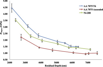
residual. H
Impact as a function of h
residual for the three tested materials is presented in Fig. 1. The H
Impact presented in Fig. 1 is corrected for pileup using Eq. (3). The percentage of pileup values with respect to h
residual
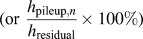 $\hbox( {{\rm{or}}\;{{{h_{{\rm{pileup,}}n}}} \over {{h_{{\rm{residual}}}}}} \times 100\% } \hbox)$
were statistically similar and remained unchanged with increasing loads. The average pileup values for AA7075-T6, AA7075-Annealed, and Ni-200 were computed to be 3.5 ± 2.3, 7.1 ± 1.3, and 3.4 ± 2.1%. As presented in Fig. 1, the materials display decreasing hardness H
Impact with increasing h
residual that extends up to several micrometers. After correcting for pileup the load independent or true dynamic hardness, H
Impact,o of AA7075-T6, AA7075-Annealed, and Ni-200 were measured to be ∼1.50 ± 0.15 GPa, ∼1.03 ± 0.07 GPa, and ∼1.38 ± 0.08 GPa, respectively. The influence of various microstructures on H
Impact,o is beyond the scope of the current work.
Dynamic hardness, H Impact as a function of residual depth, h residual.

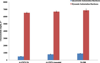
For comparing the indentation size effect of dynamic indentations with quasistatic indentations, H Static versus h residual were performed at quasistatic regime using the cube-corner indenter and corrected for pile-up in a similar fashion as H Impact versus h residual. The average percentage quasistatic indentation pileup values for AA7075-T6, AA7075-Annealed, and Ni-200 were computed to be 13.9 ± 1.7, 13.9 ± 1.3, and 9.1 ± 0.08%. The true or load independent quasistatic hardness H Static,o for AA7075-T6, AA7075-Annealed, and Ni-200 were measured to be ∼1.39 ± 0.07 GPa, ∼0.74 ± 0.02 GPa, and ∼1.13 ± 0.03 GPa, respectively. The varying strain rate sensitivities for the three materials could be obtained from the difference between H Impact,o and H Static,o. However, the current section focuses on comparing the indentation size effects between H Impact versus h residual and H Static versus h residual. The indentation size effect is quantified using the characteristic indentation depth, h*. Figure 2 presents the h* for nano-impact indentations and quasistatic indentations for AA7075-T6, AA7075-Annealed, and Ni-200. A comparison of h* between dynamic and quasistatic indentations using cube-corner tip demonstrate that h* for the nano-impact indentations are several times higher than for the quasistatic nanoindentations. The h* for dynamic indentations extend well beyond the surface regime. Hence, surface effects that influence quasistatic nanoindentations become less significant for the dynamic indentation size effects. Reference Menčík and Nemecek23 Indentation size effect in quasistatic nanoindentation hardness profile is widely explained by the Nix-Gao model, which uses geometrically necessary dislocation (GND) theories to explain this hardness reduction dependency. Reference Nix and Gao24 Recently, Arreguin et al. demonstrated a significant deviation of H Impact values from the linear Nix-Gao model, indicating departure from quasistatic indentation behavior. Reference Arreguin-Zavala, Milligan, Davies, Goodes and Brochu25 This mismatch suggests a lack of significant contribution from GNDs Reference Arreguin-Zavala, Milligan, Davies, Goodes and Brochu25 and deviation from dislocation motion by slip phenomenon during impact indentations, contributing to an enhanced decrease in hardness as function of h residual. Reference Zener and Hollomon8,Reference Armstrong, Arnold and Zerilli26,Reference Kun, Li-Ming and Shi-Sheng27
Characteristic indentation depth, h*, comparison for quasistatic and dynamic indentation hardness.

B. Strain rate profile and nonuniform loading
The deviation from the Nix-Gao model for H
Impact versus h
residual could be explained by the strain rates achieved by the nano-impact indentations. Strain rate,
 $\dot \varepsilon$
plays a key role in the behavior of net plastic flow underneath the indenter, as discussed by Tirupataiah et al.
Reference Tirupataiah and Sundararajan28
The primary characteristic of an impact loading that promotes heterogeneity, instability, and localization of strain is the nonuniformity in loading.
Reference Zener and Hollomon8
Unlike quasistatic indentations, the loading rate in nano-impact indentations decrease after coming into contact with the material, or at h = 0. A rapid decrease in
 $\dot \varepsilon$
with increase in indentation depth, h is observed. For macro-scale tests, the significantly higher
 $\dot \varepsilon$
at the early stages of an impact is a major factor in nonuniformity and the resulting instability.
Reference Zener and Hollomon8,Reference Rao and Varma29
Similarly, for nano-impact indentations the nonuniformity in loading is facilitated by the rapidly decreasing
 $\dot \varepsilon$
versus h curves, as shown in Fig. 3. The impact strain rate,
 ${\dot \varepsilon _{{\rm{Impact}}}}$
, is the
 $\dot \varepsilon$
at the point of impact. The
 ${\dot \varepsilon _{{\rm{Impact}}}}$
values for the loads ranging from 10 to 100 mN are statistically similar and have an average value of 1.34 × 10⁴ ± 0.1 × 10⁴ s−1. The overall indentation strain rate is given by the relationship
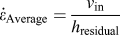 ${\dot \varepsilon _{{\rm{Average}}}} = {{{v_{{\rm{in}}}}} \over {{h_{{\rm{residual}}}}}}$
.
Reference Song, Shen, Su, Lai and Chiu6
On the other hand, the
 ${\dot \varepsilon _{{\rm{Average}}}}$
value of roughly 2.3 × 10² ± 0.8 × 10² s−1 for loads 10–100 mN also lie in the impact regime, which ensures the required energy localization and consequent promotion of dynamic deformation mode. In essence, the high
 ${\dot \varepsilon _{{\rm{Impact}}}}$
and
 ${\dot \varepsilon _{{\rm{Average}}}}$
, and excessively high
 $\dot \varepsilon$
values at initial depths of penetration promote the dynamic nonuniformity and localization of deformation in a nano-impact indentation.
Strain rate profiles,
 $\dot \varepsilon$
, of AA7075-T6, AA7075-Annealed, and Ni-200 at 50 mN load.

C. F versus d and plastic wave generation during indentation
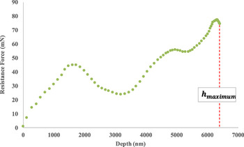
A representative resistance force versus indentation depth curve (F versus h) curve has been displayed in Fig. 4 using a 50 mN impact load on AA7075-T6, AA7075-Annealed and Ni-200. The wave like F versus h profile obtained in Fig. 4 suggests a dynamic deformation behavior during the nano-impact indentation process. Complete explanation of this wave-like deformation mechanism has been discussed in the literature.
Reference Johnson16,Reference Qiao, Yang and Bobaru17
Such wave-like formations have been discussed by Meyers to be the transmission of stress pulses exceeding the amplitude of elastic limit.
Reference Meyers30
Lawn et al. have reported the presence of fluid-like dynamic flow in metals.
Reference Lawn, Hockey and Wiederhorn14
The occurrence of such viscous plastic flow has been demonstrated for deformations with
 $\dot \varepsilon > 1000\;{{\rm{s}}^{ - 1}}$
.
Reference Cheval and Priester31–Reference Kumar and Kumble33
As seen from a representative profile of
 $\dot \varepsilon$
versus h in Fig. 3, a significant portion of a nano-impact deformation profile lies above
 $\dot \varepsilon$
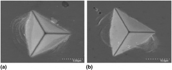
of 1000 s−1. This explains the wave generation in the F versus h profile shown in Fig. 4. Furthermore, the viscous flow phenomenon is reinforced by the presence of wave-like folds on the periphery of indentations, as illustrated in the representative images of 50 mN impact indentation load for AA7075-T6 and AA7075-Annealed in Fig. 5.
A typical F versus h curve h = 0 to h = h max, shown for Ni-200 at 50 mN load.

Wave-like patterns in the pile-up regions of 50 mN indentation imprints, shown for (a) AA7075-T6 and (b) AA7075-Annealed.

D. Deformation related energy during impact
The quantification of energy dispersed toward creation and transmission of plastic waves is an important step toward evaluating the dynamic behavior of the nano-impact indentations. The assessment of energetics of deformation is primarily done using the plastic energy dissipated during indentation, ΔE Plastic and the plastic work of deformation during indentation, W Plastic. The components of the ΔE Plastic and W Plastic in the context of indentation size effect or the decreasing H Impact values with respect to the increase indentation depths (or indentation sizes), to the best of our knowledge, has not been reported or discussed in the literature. ΔE Plastic and W Plastic is calculated using Eqs. (4) and (5), respectively:
 $$\displaylines{ \Delta {E_{{\rm{Plastic}}}} = \Delta KE = K \cdot {E_{{\rm{initial}}}} - K \cdot {E_{{\rm{final}}}} \cr = {1 \over 2}\left( {{m_{{\rm{effective}}}} \times v_{{\rm{in}}}^2} \right) - {1 \over 2}\left( {{m_{{\rm{effective}}}} \times v_{{\rm{out}}}^2} \right) \quad ,}}$$
 $${W_{{\rm{Plastic}}}} = \int_0^{{h_{{\rm{residual}}}}} {F \times {\rm{d}}x} \quad .$$
During quasistatic nanoindentation, the ΔE Plastic and W Plastic of deformation are equal. Reference Andrews, Giannakopoulos, Plisson and Suresh34 However, due to energy dissipation in the form of plastic waves during dynamic indentations, ΔKE Plastic is greater than ΔW Plastic. Reference Andrews, Giannakopoulos, Plisson and Suresh34 The energy related to the dynamic response of materials could be termed as ΔE Dynamic. ΔE Dynamic is calculated using Eq. (6):
 $$\Delta {E_{{\rm{Dynamic}}}} = \Delta K{E_{{\rm{Plastic}}}} - {W_{{\rm{Plastic}}}}\quad .$$
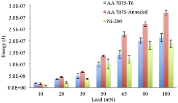
Increasing indentation loads cause an increase in energy of impact, leading to a greater overall dynamic response. Increasing ΔE Dynamic values with increasing impact loads have been displayed in Fig. 6.
ΔE Dynamic as function of increasing impact loads 10–100 mN for AA7075-T6, AA7075-Annealed, and Ni-200.

In Fig. 6, AA7075-Annealed displays the highest ΔE Dynamic at almost every load. This might be attributed to the lower hardness values of AA7075-Annealed. The increased viscous flow or plastic waves has been related by Tabor to the softness in a material, explaining the higher ΔE Dynamic in the relatively soft AA7075-Annealed. Reference Tabor35 A significant percentage of ΔE Plastic is converted to ΔE Dynamic during the nano-impact indentations on the three materials. For example, at 100 mN the percentage of ΔKE Plastic converted to ΔE Dynamic; %(ΔE Dynamic/ΔKE Dynamic) for AA7075-T6, AA7075-Annealed, and Ni-200 are 60 ± 1, 44 ± 4%, and 41 ± 2% respectively. High values of %(ΔE Dynamic/ΔKE Dynamic) represent the energy dispersion toward plastic wave generation in the materials, further reinforcing the evidence of dynamic response induced in the materials by the nano-impact indentations.
E. Characterization of indentation imprint and strain-field
The nano-impact indentations featuring: (a) impact regime strain rates, (b) sharp cube-corner indenter tip, and (c) dynamic stress-wave creation provide an ideal condition for localization of strain. The nonuniformity of impact loading, illustrated by
 $\dot \varepsilon$
profiles in Fig. 3, causes instability due to heterogeneity in dislocation distribution
Reference Armstrong and Walley36
and hence strain.
Reference Zener and Hollomon8
The instability induces stress wave generation, as indicated by Figs. 5–7. Previous studies have discussed the generation of extra dislocations by the waves that result in increased flow stress and localized strain.
Reference Arreguin-Zavala, Milligan, Davies, Goodes and Brochu25,Reference Armstrong and Walley36
Localized strain during high strain rate deformation has been reported to result in adiabatic softening.
Reference Zener and Hollomon8,Reference Rajaraman, Jonnalagadda and Ghosh37,Reference Chou, Robertson and Rainey38
The dynamic instability has been discussed to induce abrupt generation and release of extremely localized thermal energy.
Reference Armstrong, Coffey and Elban39,Reference Coffey and Armstrong40
If the rate of heat generation is higher than the rate of heat conduction to the bulk, a thermally induced local softening or adiabatic softening is possible.
Reference Rajaraman, Jonnalagadda and Ghosh37,Reference Hodowany, Ravichandran, Rosakis and Rosakis41
Macro-scale indentations have widely shown to cause adiabatic softening, or
 ${{{\rm{d}}H} \over {{\rm{d}}\varepsilon}} \lt 0$
, at high ɛ and
 $\dot \varepsilon$
.
Reference Sundararajan and Tirupataiah15,Reference Tabor35
Similarly, the decreasing H
Impact as a function of h
residual, or
 ${{{\rm{d}}{H_{{\rm{Impact}}}}} \over {{\rm{d}}{h_{{\rm{residual}}}}}}$
, are in agreement with the thermally induced softening witnessed in several macro-scale impact tests.
Reference Zener and Hollomon8,Reference Lawn, Hockey and Wiederhorn14,Reference Sundararajan and Tirupataiah15,Reference Tirupataiah and Sundararajan28,Reference Tabor35,Reference Johnson and Cook42
However, strain localization is a pre-requisite for the dynamic softening phenomenon. Strain localization due to nano-impact indentations is assessed by characterizing the extent of strain fields around the indents for a range of residual depths. The strain affected zones of the cube-corner indenter at dynamic strain rate regime are compared to the affected zones at quasistatic strain rate regime at comparable indentation depths to assess the role of strain rate on the strain localization phenomenon.
Band contrast image of quasistatic indent on Ni-200 (a) and the GROD contour map, indicating extent of strain effect, l maximum (b).
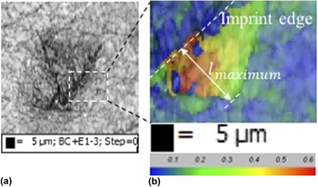
GROD function has been previously used in literature to characterize process induced plastic strain in metals. Reference Kumar and Pollock43 GROD function uses crystal rotation at each point with respect to the average orientation of the grain to generate a contour map, describing strain field induced by the indentation. The contour maps were utilized to measure the extent of strain affected zones of the indent imprints. The contour maps displayed a general reduction in GROD angles with increasing distance from the edges of the indentation imprints, until the deviation angles became negligible. From the GROD maps, the maximum length of strain effect, l maximum, is measured perpendicular to the edge of the triangular indentation imprint. An illustration of the color contour based on GROD angles has been presented in Fig. 7, a representative case shown for a quasistatic indent on Ni-200. For the quasistatic indent, the GROD angles decrease from ∼0.6° to ∼0° over a maximum length of ∼17 μm. The presence of strain gradient in quasistatic indentations using cube-corner tips has also been detailed elsewhere. Reference Rester, Motz and Pippan44 On the other hand, a GROD contour map of a nano-impact indent on Ni-200 shows negligible strain field around the indent, indicated by the negligible GROD contouring. Instead, in the case of nano-impact indents on Ni-200, the maximum strain seems to be concentrated in a narrow band in the extreme vicinity of the imprint edges, generating very low l maximum values ranging between 0.5 and 2 μm. The strain affected area is associated to significant crystallographic distortions caused by the impact indentations, potentially causing lack of crystal orientation indexing and therefore lack of signal in such areas. AA7075-T6 and AA7075-Annealed do not display such excessive localization of strain as Ni-200. Dynamic indentations on the two aluminum alloys display some degree of strain field. In comparison to quasistatic indentations on AA7075-T6 and AA7075-Annealed however the l maximum is much lower. Table I presents the ratio of maximum length of strain affected region to the average vertex size of the indentation imprints, l maximum/l avg.indent vertex for AA7075-T6, AA7075-Annealed, and Ni-200. Varying h residual values are obtained by the nano-impact indentation loads of 1 mN, 10 mN, 50 mN, and 100 mN. In Ni 200, l maximum/l avg.indent vertex for nano-impact indentations for the given h residual values range between 0.056 ± 0.012 and 0.11 ± 0.012. For AA7075-T6 the l maximum/l avg.indent vertex ranges between 0.13 ± 0.02 and 0.37 ± 0.03. Based on Table I, the l maximum/l avg.indent vertex at quasistatic and dynamic indentations for AA7075-T6, AA7075-Annealed, and Ni-200 at similar h residual values could be compared. For AA7075-T6, at h residual of 7.2 ± 0.4 and 6.9 ± 0.13 μm for quasistatic and dynamic indentation respectively, l maximum/l avg.indent vertex for quasistatic indents is significantly larger than the dynamic indents. Similarly, quasistatic and dynamic indents at h residual of 8.1 ± 0.1 and 8 ± 0.34 for AA7075-Annealed, and h residual of 7.7 ± 0.20 and 8 ± 0.4 for Ni-200 generate l maximum/l avg.indent vertex ratio for quasistatic indents that far exceeds the ratio for dynamic indents, demonstrating the effect of strain rates on the strain localization process.
h residual and the corresponding l maximum/l avg.indent vertex for dynamic and quasistatic indentations on AA7075-T6, AA7075-Annealed, and Ni-200.

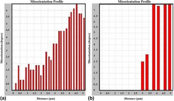
The GROD contour maps could be complemented using line misorientation angle mapping measured normal to the imprint edges, yielding 2-dimensional intra-granular misorientation gradients. The magnitude of intra-granular misorientation angle represents the degree of distortion due to plastic strain in a grain. It was previously discussed that the dynamic indentations for Ni-200 generate a narrow band of heavily deformed region in the imprint vicinity, displaying negligible strain field and hindering line misorientation measurements. Quasistatic indentations for Ni-200, on the other hand, display a gradual decrease in misorientation with increasing distance from the imprint. The dynamic indents on Ni-200 displayed a relatively higher localization of strain compared to AA7075-T6 and AA7075-Annealed. The comparison of intra-granular strain affected regions generated by quasistatic and dynamic indentations is more easily performed for AA7075-T6. Figure 8 presents the misorientation angle versus distance from the edge of the indent imprint for quasistatic and dynamic indentations on AA7075-T6. For the dynamic indentations, negligible reduction in misorientation angles are observed throughout the length of the affected regions. The misorientations appear to be similar throughout the strain affected length until dropping to very low or negligible values beyond the affected length. Similar to Ni-200, the strain affected region of quasistatic indentations on AA7075-T6 display a gradual decrease of misorientation angles starting with maximum values at imprint vicinity, as shown in Fig. 8 for the same line distance as that of the dynamic indentation. Comparison of quasistatic and dynamic indentations in AA7075-Annealed follows similar trend as AA7075-T6. Overall, the considerable degree of strain localization by dynamic indentations, compared to quasi-static indentations, suggests the adiabatic nature of deformation toward the resultant softening effect seen for H Impact versus h residual in Fig. 1.
Line misorientation angle mapping from unaffected region to edge of indent imprint, angles measured relative to the starting point, for quasistatic (a) and dynamic (b) indentations for AA7075-T6.

IV. CONCLUSION
The dynamic response of materials during nano-impact indentations is studied by assessing the size (indentation depth) effect of indentations and the possible mechanisms that cause the effect. The size effect in the dynamic indentations display characteristic depth values, h*, several times higher than the quasistatic indentations for AA7075-T6, AA7075-Annealed, and Ni-200. The relatively excessive h* for the nano-impact indentations were investigated by assessing the dynamic properties of the impact indentations. First, the nano-impact indentations demonstrate rapid fall in strain rate,
 $\dot \varepsilon$
, versus penetration depth profiles, h, showing similarities with macro-scale impacts reported in literature. Second, the force versus penetration depth (F versus h) curves indicate plastic wave formation during the nano-impact indentations. Third, the energy contributed toward plastic waves, ΔE
Dynamic, was found to be significant and contributed to approximately 44–60% of the total energy supplied at the highest impact load of 100 mN. The nano-impact indentation imprint were investigated for strain distribution using GROD and line misorientation analysis using EBSD maps. Negligible or significantly lower strain fields generated as well as the negligible gradient in strain displayed by the dynamic indentations in comparison to quasistatic indentations indicated considerable strain localization and possible adiabatic softening as a consequence of the impact localization of strain.
ACKNOWLEDGMENTS
The authors would like to gratefully acknowledge the help and support of Priyadarshi Behera for his role in static nanoindentation hardness measurements and Nicolas Brodusch for his help with the ion-milling technique.