


I. INTRODUCTION
An antenna is a device, which is used to transfer guided electromagnetic waves (signals) to radiating waves in an unbounded medium, usually free space and vice versa (i.e. in either the transmitting or receiving mode of operation). Antennas are an essential part in communication systems, so that the antennas are frequency-dependent devices, hence each antenna is designed for a certain frequency band.
This paper has introduced a new compact ultra-wideband (UWB) traveling-wave antenna based on metamaterial (MTM) composite right/left-handed transmission lines (CRLH-TLs) with good radiation patterns. Recently, the MTM-based TLs have been developed and shown to exhibit unique features of anti-parallel phase and group velocities (v p – ‖ v g ); and zero propagation constant at a certain frequency in the fundamental operating mode [Reference Ziolkowski and Kipple1, Reference Eleftheriades, Grbic and Antoniades2]. These MTMs have been used to realize novel planar antennas. MTM technology may be caused to designing antenna structures with physically small size, whereas this antenna can be employed for large frequency bandwidth [Reference Alibakhshi Kenari3, Reference Alibakhshi Kenari4]. The proposed traveling-wave MTM antenna presents the advantages such as reduction in physical size and spread in bandwidth than the conventional antennas, also unidirectional radiation patterns, planar, low loss, ease of fabrication, and simple topology are desirable properties of this antenna. Hence, the presented minimized UWB antenna can be integrated into radio frequency (RF) components for the embedded electronic systems.
II. DESIGN PROCESS OF THE PROPOSED TRAVELING-WAVE ANTENNA
The proposed antenna design process is based on a simple topology that incorporates the printed planar patches and spiral inductors accompanying via holes connected to the ground plane. This topology makes it possible to combine the antenna with integrated RF electronics. This paper employs the standard manufacturing techniques on the radiation patches to create the printed planar b-shaped slits, which lead to downsizing of the structure and play the roles of the series left-handed (LH) capacitances (C L ). Furthermore, with modeling the smaller values of the b-shaped slits by optimization of their dimensions, the wideband performances can be obtained. Besides the minimized size and the broad bandwidth properties, the radiation patterns of the antenna are very important. By applying the four unit cells to form a b-shape, and also design the appropriate inductive elements such as spiral inductors and metallic via holes, employing the larger aperture size and the uniform excitation mechanism the good radiation patterns can be achieved.
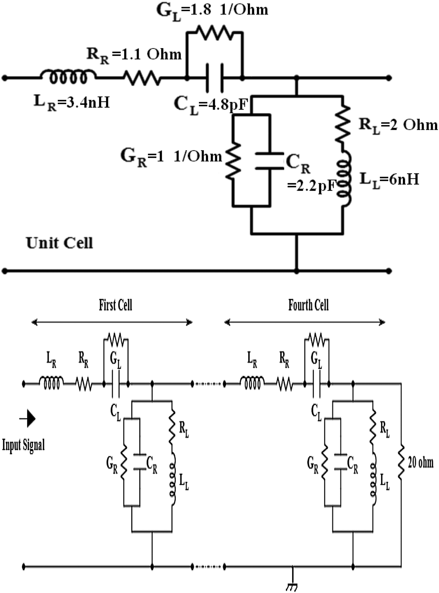
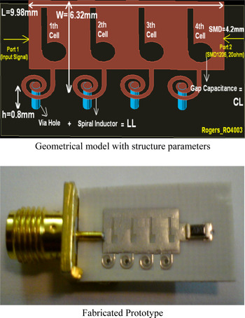
The antenna structure is made of four CRLH unit cells, so that each unit cell includes a b-shaped slit that is printed on the rectangular radiation patch, by the standard manufacturing technique and a spiral inductor connected to the ground plane through a vertical via. The circuit model of the proposed traveling-wave antenna is shown in Fig. 1.
Circuit model of the proposed traveling-wave antenna constructed of four unit cells accompanying the circuit parameters values.
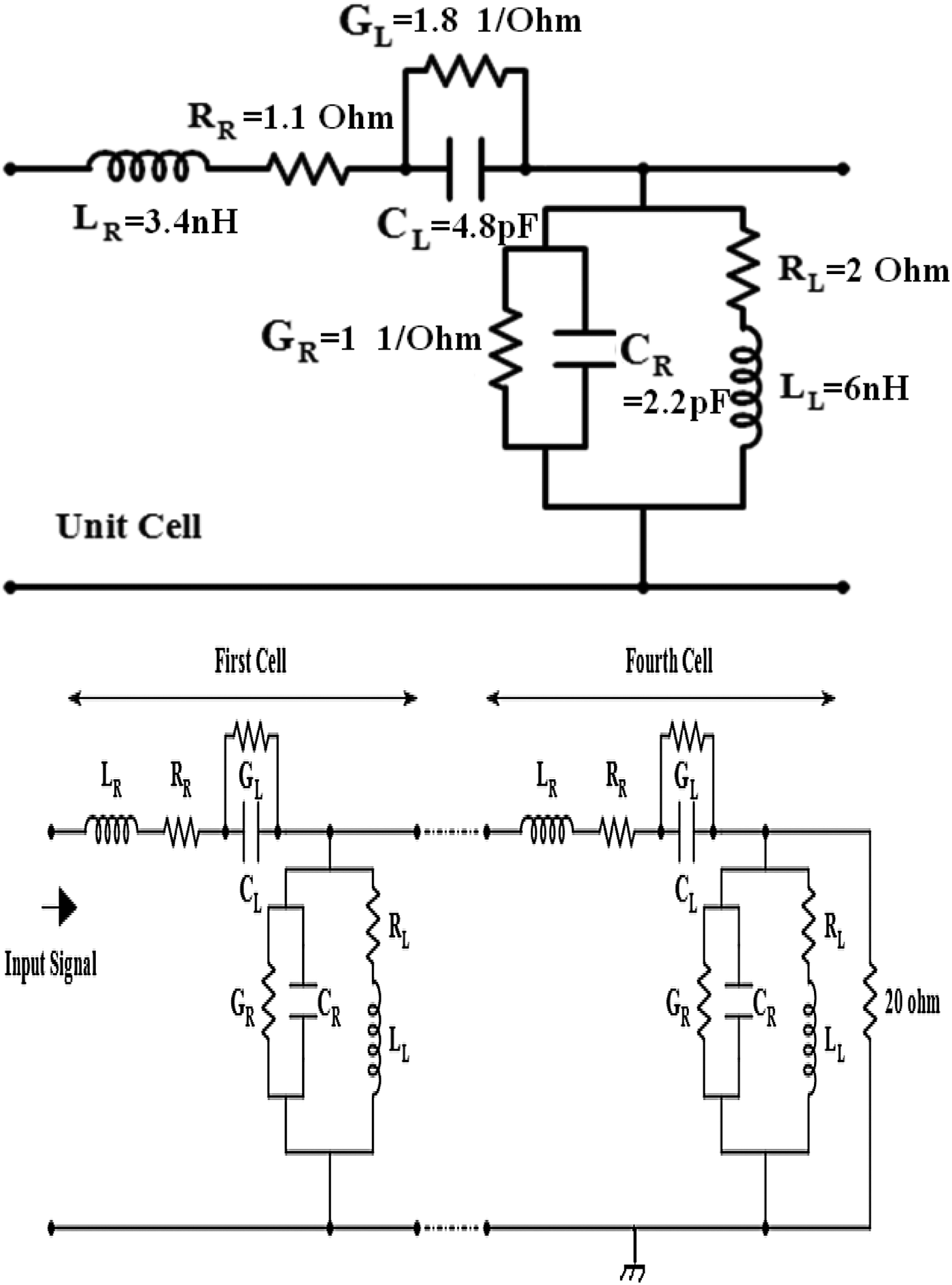
Also, Fig. 2 shows the configuration of the antenna. In each unit cell, the printed b-shaped slit establishes the series capacitance (C L ) and the spiral inductor accompanying via act like shunt inductance (L L ). The series capacitance C L can be adjusted by setting the dimensions of the printed b-shaped slits, this feature provides another superior capability that can be used to change the performance of the antenna.
Configuration of the traveling-wave b-shaped antenna composed of four unit cells.

In addition to C L and L L , the TLs possess the right-handed (RH) parasitic effects that can be seen as shunt capacitances (C R ) and series inductances (L R ). The shunt capacitances C R mostly come from the gap capacitances between the patch and the ground plane, and unavoidable currents flow on the patches to establish the series inductances L R , which indicates that these capacitances and inductances cannot be ignored. The RH and LH losses of the structure are modeled by R R , G R , R L , and G L . In this structure, to increase the antenna aperture efficiency the uniform excitation mechanism is used by applying two ports (ports 1 and 2), whereas port 1 is excited by the input signal and port 2 is matched to 20 Ω load impedance of the SMD1206 component. The SMD1206 component is connected to the ground plane through via hole and occupies the place of 4.2 mm of the total area of the antenna structure.
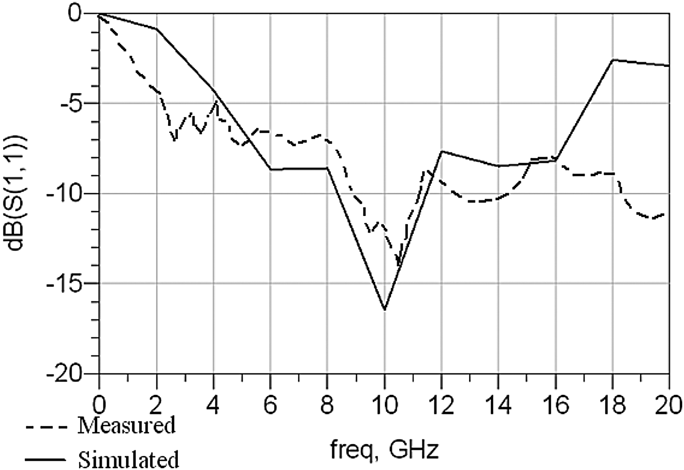
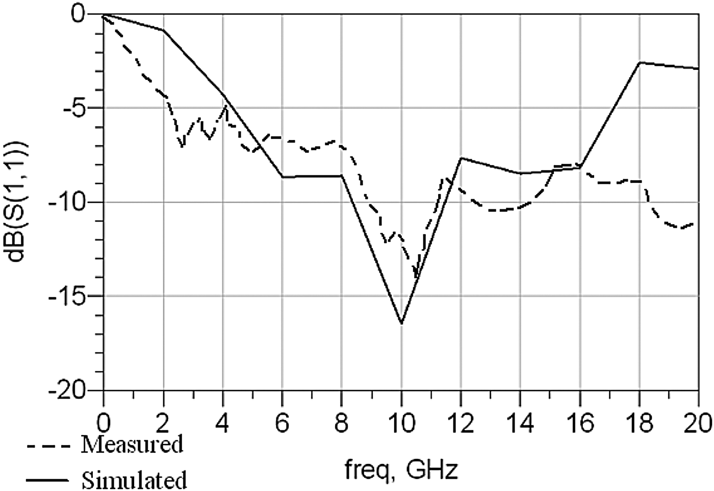
The presented traveling-wave CRLH MTM antenna is built on a Rogers_RO4003 substrate with thickness of h = 0.8 mm, dielectric constant of ε r = 3.38 and tanδ = 0.0022. In this structure, size reduction of the compact printed b-shaped slits is used, so that the antenna's physical size is 14.18 × 6.32 × 0.8 mm3 (0.42λ0 × 0.19λ0 × 0.024λ0, where λ0 is the free space wavelength at 9 GHz). Also the antenna has 2.1 GHz measured bandwidth from 9 to 11.1 GHz, and 3 GHz simulated bandwidth from 8.5 to 11.5 GHz, which corresponds to 21% practical impedance bandwidth. Figure 3 exhibits the simulated and measured reflection coefficients (S 11 < −10 dB) of the antenna. These results make the proposed antenna to have a very broad bandwidth and are compact enough to fit on the embedded electronic systems and portable wireless communication devices.
Simulated and measured reflection coefficients (S 11 parameters).
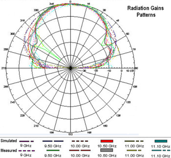
In addition to minimization and UWB properties, the simulated gains and radiation efficiencies of the antenna at operating frequencies of f = 9, 9.5, 10, 10.5, 11, and 11.1 GHz are 6.5 dBi and 56.9%, 6.8 dBi and 64.3%, 7 dBi and 73.2%, 7.4 dBi and 83.5%, 7.1 dBi and 76.1%, and 6.8 dBi and 69.3%, respectively. Also, the measured amounts of these radiation parameters at the above frequencies are 6.1 dBi and 52.3%, 6.5 dBi and 60.1%, 6.8 dBi and 69.4%, 7 dBi and 78.52%, 6.75 dBi and 69.6%, and 6.4 dBi and 65.8%, respectively. The simulated and measured radiation gain patterns in the main cuts at several operating frequencies are plotted in Fig. 4.
Radiation gain patterns in the main cuts at different frequencies.

As is clear from Fig. 4, the antenna radiation patterns have unidirectional specifications.
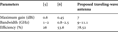
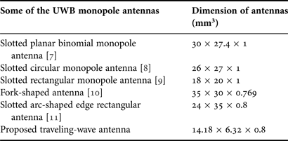
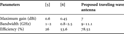
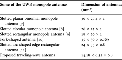
To validate the design procedures, the proposed traveling-wave antenna is compared with several conventional antennas and their radiation characteristics and dimensions are summarized in Tables 1 and 2, respectively.
Radiation characteristics of the compact conventional antennas in comparison with the proposed miniature traveling-wave antenna.
Dimensions of some of the UWB conventional antennas in comparison to the proposed UWB traveling-wave antenna.
According to the results, the proposed traveling-wave antenna is attractive and suitable for use in the embedded electronic systems and wireless communication devices.
It should be noted that, the simulated results were obtained using an Agilent ADS full-wave simulator.
III. CONCLUSION
A CRLH traveling-wave antenna with miniature size, UWB properties, and unidirectional radiation patterns has been presented and is made to exhibit substantially dimension, bandwidth, and radiation properties than to conventional miniature and UWB antennas, which are located in Tables 1 and 2. The physical size of the proposed antenna is 0.42λ0 × 0.19λ0 × 0.024λ0 in terms of the free-space wavelengths at 9 GHz equivalent to 14.18 × 6.32 × 0.8 mm3. Also, this antenna can be used for frequency band of 9–11.1 GHz, so that at its resonant frequency of f r = 10.5 GHz presents the gain and radiation efficiency equal to 7 dBi and 78.52%, respectively. Especially, the presented miniature UWB antenna based on MTM CRLH-TLs due to its versatile characteristics and its high performances are expected to find wide applications in the future.
ACKNOWLEDGEMENTS
The author would like to express his sincere thanks to Iran Telecommunication Research Center (ITRC) with contract number of 6987/500/T, the microwave and millimeter wave laboratory of the Amirkabir University of Technology (Tehran Polytechnic) and the antenna laboratory of the K. N. Toosi University of Technology.
 Mohammad Alibakhshi Kenari was born in 24 February 1988 at Iran, Mazandaran, Freidounkenar. He received his B.S. and M.S. degrees in the field of Electrical Engineering-Telecommunication from the Islamic Azad University, Najafabad Branch at Iran on 19 February 2010 and the Islamic Republic of Iran Shahid Bahonar University of Kerman on 5 February 2013, respectively. So far, he has published over 10 papers, and also works as a reviewer in the several ISI journals and is a Member of the Technical Program Committee (M-TPC) of some of the international conferences such as MobiWIS 2014, DPNoC 2014 and CICN 2014.
His researches interests include microwave and millimeter wave circuits, antennas and waves propagation, metamaterial applications, integrated RF technologies, embedded systems, electromagnetic waves applications and wireless telecommunication systems.



Target article
Retraction Notice
Related commentaries (6)
A new compact UWB traveling-wave antenna based on CRLH-TLs for embedded electronic systems
Designing an ultra-wideband electromagnetic waves receiver with new architecture for RF and wireless applications
Introducing the new wideband small plate antennas with engraved voids to form new geometries based on CRLH MTM-TLs for wireless applications
Miniaturized printed monopole antenna with applying the modified conductor-backed plane and three embedded strips based on CPW for multi-band telecommunication devices
Modeling and constructing the microstrip notch-loaded rectangular S-shaped patch antennas using L-strip feeding for multi-band frequency performances in the recent wireless telecommunication systems
Significant measureable development of inductance gain per unit of space in loop fractals