I. INTRODUCTION
Mechanical properties of low-density nanoporous solids, such as aerogels (AGs), have been a subject of numerous previous studies (see, for example, Refs. Reference Pekala, Alviso and LeMay1–Reference Kucheyev, Hamza, Satcher and Worsley10 and references therein). Depth-sensing indentation (DSI) has emerged as a very convenient tool for the evaluation of mechanical properties of AGs.Reference Moner-Girona, Roig, Molins, Martinez and Esteve4–Reference Fan, Hartshorn, Buchheit, Tallant, Assink, Simpson, Kissel, Lacks, Torquato and Brinker7, Reference Worsley, Kucheyev, Satcher, Hamza and Baumann9, Reference Kucheyev, Hamza, Satcher and Worsley10 A low-density nanoporous system that has received the most attention is the silica (SiO2) AG. All previous DSI studies of silica AGs have been performed at room temperature.Reference Moner-Girona, Roig, Molins, Martinez and Esteve4, Reference Lucas, Doescher, Ebenstein, Wahl and Rolison5, Reference Fan, Hartshorn, Buchheit, Tallant, Assink, Simpson, Kissel, Lacks, Torquato and Brinker7, Reference Kucheyev, Hamza, Satcher and Worsley10 In this case, negligible time-dependent deformation for full-density silica is expected because room temperature is much lower than silica’s glass transition temperature (~1170 °C).Reference Angell11 Hence, with an exception of our recent report,Reference Kucheyev, Hamza, Satcher and Worsley10 all such previous studies have not been concerned with controlling strain rates and with consequences of possible time-dependent deformation.
In this work, we show that, in contrast to our expectations based on the behavior of full-density silica, nanoporous silica AGs exhibit pronounced time-dependent deformation effects during room temperature DSI experiments. We attribute such time-dependent deformation to stress corrosion fracture of nanoligaments. It is consistent with a large surface-to-bulk atomic fraction of nanoligaments amenable to stress corrosion fracture and with our recent findingsReference Kucheyev, Hamza, Satcher and Worsley10 suggesting that inelastic deformation of silica AGs during DSI is controlled by nanoligament fracture rather than by plastic flow.
II. EXPERIMENTAL
The monolithic silica AGs studied in this work were prepared, as reported in detail previously,Reference Kucheyev, Hamza, Satcher and Worsley10 by base catalyzed hydrolysis of tetramethylorthosilicate [Si(OCH3)4] in an aqueous methanol solution. An average bulk density of the AG of ~340 mg cm−3 (corresponding to ~15% of the full-density silica) was determined by measuring the dimensions and mass of the monolith. The original monolith, a right cylinder with a diameter and height of ~20 and 2 cm, respectively, was shaped to ~2 × 2 × 2 cm3 cubes by fracturing along scratches made on monolith surfaces. The fracture surfaces prepared in this way were free from “skin layers” (i.e., surface layers of a densified and fractured material) and contamination debris present on surfaces of as-cast and machined silica AG monoliths, respectively.Reference Kucheyev, Hamza, Satcher and Worsley10, Reference Kucheyev, Toth, Baumann, Hamza, Ilavsky, Knowles, Saw, Thiel, Tileli, van Buuren, Wang and Willey12
Such fracture surfaces were subjected to indentation in an MTS XP Nanoindenter (MTS Systems Corp., Eden Prairie, MN) with a spherical sapphire indenter with a radius of 496 μm, two pyramidal diamond indenters (Berkovich and cube corner three-sided pyramids) with semi-included angles of equivalent cones of 72.1° and 53.9°, respectively, and a diamond flat punch indenter with an effective radius of 31 μm. All indentation experiments were carried out at room temperature in laboratory air. The loading rate (dP/dt) was continuously adjusted to keep a constant representative strain rates ε˙* of 6 × 10⁻²s−1 for pyramidal and flat punch indents and of 10−3s−1 for spherical indents. (A lower ε*˙ for spherical indents was necessitated by the loading rate limitations of the DSI instrument used.) The strain rates were defined as in Ref. 10. To evaluate time-dependent behavior, the maximum load was kept constant for 20 min. The unloading rate was kept constant and equal to the maximum loading rate of the cycle. The Oliver–Pharr methodReference Oliver and Pharr13 was used to calculate indentation stress (σ*, the average contact pressure) with an assumption of Poisson’s ratios of diamond, sapphire, and AGs of 0.07, 0.23, and 0.20, respectively, and Young’s moduli of diamond and sapphire of 1141 and 425 GPa, respectively.Reference Kucheyev, Hamza, Satcher and Worsley10, Reference Abramoff and Klein14, Reference Daughton, MacDonald and Mulders15 Representative strain for flat punch indentation was defined asReference Kucheyev, Hamza, Satcher and Worsley10 ε*punch = 2h/πR, where h is the indenter tip displacement measured from the point of initial surface contact, and R is the effective radius of the indenter.
Time-dependent deformation processes are commonly studied in creep experiments [evolution of strain ε(t) under constant stress σ = const] and stress relaxation experiments [σ(t) for ε = const]. For pyramidal indentation, representative strain ε* is defined by the pyramidal angle only and is independent of the load or displacement.Reference Kucheyev, Hamza, Satcher and Worsley10 Hence, for experiments when the indenter displacement is measured as a function of time during constant (static) load, pyramidal indentation can be used to study stress relaxation processes. Flat punch indentations have constant σ* during static loading and can be used for evaluation of creep effects. (We note, however, that a direct comparison of such DSI creep and stress relaxation experiments with conventional macroscopic uniaxial load experiments is not straightforward. Indeed, for DSI, stress fields under the indenter are complex, and the deformation volume increases with indenter penetration. Hence, for pyramidal indentation, characterized by load- and displacement-independent ε*, there is an effective strain rate due to a changing deformation volume. Similarly, for static load flat punch experiments, characterized by constant σ*, indenter penetration is accompanied by deformation volume expansion and effective stress changes in the previously undeformed volume. Such effects of changing deformation volumes are important for an accurate quantitative modeling of DSI creep and stress relaxation processes, which is beyond the scope of this work.)
III. RESULTS AND DISCUSSION
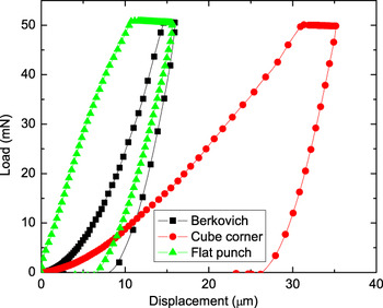
Figure 1 shows load–displacement curves for silica AGs indented with pyramidal and flat punch tips to a maximum load of 50 mN, which was held constant for 20 min before unloading. It reveals that, for all three cases, indenter continues to penetrate into the sample when the load is held constant. Furthermore, it can be seen from Fig. 1 that values of penetration during such a load hold segment (referred to below as creep displacement) depend on the indenter geometry and are ≳1 μm. Such creep displacements are much larger than typical thermal-drift related ≲0.03 μm observed in our experiments of full density amorphous SiO2 indented under similar loads with a 20 min hold segment.
Continuous load–displacement curves for nanoporous silica indented with Berkovich, cube corner, and flat punch tips (as indicated) to a maximum load of 50 mN and a hold time at the maximum load of 20 min.

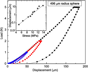
Time-dependent deformation of AGs for spherical indentation is illustrated in Fig. 2, showing load–displacement curves for a hold time at the maximum load of 20 min. It is seen from Fig. 2 that, although negligible creep effects are observed for loads ≲1 N, the creep displacement increases with increasing maximum load. This effect is better illustrated in the inset in Fig. 2, revealing an exponential dependency of the creep displacement on the maximum indentation stress applied. For static load experiments with spherical tips, both σ* and ε* are changing when the indenter experiences creep displacement. Hence, for a more quantitative analysis of the phenomenon, we turn to static load flat punch and pyramidal indentation, for which σ* and ε*, respectively, remain constant. (We note that creep effects can also be studied quantitatively in spherical DSI experiments by continually increasing load during testing, as reported by Basu et al.Reference Basu, Radovic and Barsoum16)
Continuous load–displacement curves for nanoporous silica indented with a 496-μm-radius spherical indenter to maximum loads of 1, 2, and 5 N with a hold time at the maximum load of 20 min. The inset reveals an exponential dependency of the creep displacement on the applied stress.

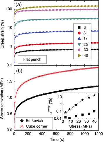
For flat punch indentations, changes in ε* as a function of hold time t at different maximum loads (converted to creep stress σ* by dividing load by contact area) are shown in Fig. 3(a). It reveals that ε*(t) is well described by an empirical logarithmic law ε*(t) = ε*(0) + αcreepln(t/t creep + 1), where αcreep and t creep are fitting parameters. An exponential dependency of the creep constant αcreep on the applied stress, obtained from fitting experimental data, is shown in the inset in Fig. 3(b). A deviation from the exponential trend for large loads resulting in stresses ≳30 MPa, seen in the inset in Fig. 3(b), is attributed to very large initial strains ε*(0) of ≳150% and extensive fracture, when the Sneddon’s description of ε* is no longer valid.Reference Kucheyev, Hamza, Satcher and Worsley10
(a) Creep strain and (b) changes in average contact pressure as a function of the hold time at the maximum load for nanoporous silica indented (a) with a flat punch tip to maximum loads corresponding to creep stresses indicated in the legend (in MPa) and (b) with Berkovich and cube-corner tips to a maximum load of 50 mN. Solid lines in both (a) and (b) are fits with logarithmic creep and stress relaxation laws. The inset in (b) reveals an exponential dependency (stars) of the creep constant αcreep on the applied stress for flat punch indentation of silica aerogels. The inset also shows a stress dependency (squares) of αcreep for flat punch indentations of a graphitic-carbon-based aerogel with a density of 295 mg cm−3.

The stress relaxation behavior studied in pyramidal indentation experiments is illustrated in Fig. 3(b), revealing an empirical logarithmic stress relaxation law σ*(t) = σ*(0) − αrelaxationln(t/t relaxation + 1), with fitting parameters αrelaxation of 0.21 and 0.23 MPa for Berkovich and cube-corner tips, respectively. We note that ε* is much larger for cube corner than for Berkovich tips used (~37% versus ~16%).Reference Kucheyev, Hamza, Satcher and Worsley10 Hence, results from Fig. 3(b) show that ε* influences the initial stage of stress relaxation, while the evolution of σ* for t ≳ 100 s is independent of ε*, with σ* for the cube-corner tip being ~70% larger than for the Berkovich tip, independent of time. Such different initial stress relaxation behavior for these two pyramidal tips is not unexpected given vastly different inelastic deformation revealed in our previous study.Reference Kucheyev, Hamza, Satcher and Worsley10 Deformation of silica AG under a Berkovich tip is largely elastic with fracture proceeding via the formation of “cone cracks” at the contact line where tensile stresses are maximum. In contrast, extensive pore collapse occurs throughout the contact area of the cube-corner tip.Reference Kucheyev, Hamza, Satcher and Worsley10
The time-dependent deformation at longer time scales appears to be controlled mainly by the average contact pressure rather than by stress field asperities inherent to pyramidal and flat punch indenter geometries. Indeed, Berkovich and cube-corner tips generate similar average contact pressures in silica AGs,Reference Kucheyev, Hamza, Satcher and Worsley10 and longer time scale stress relaxation processes are similar for Berkovich and cube-corner tips [Fig. 3(b)]. Moreover, creep effects are observed for spherical indentation (Fig. 2) that generates stress fields without asperities.
We attribute the pronounced time-dependent deformation, observed for silica AGs and not in full-density silica, to stress corrosion fracture of nanoligaments interconnected into a continuous three-dimensional nanoporous structure. Indeed, our recent findingsReference Kucheyev, Hamza, Satcher and Worsley10 suggest that inelastic deformation of silica AGs during DSI is controlled by ligament fracture rather than by plastic flow. Fracture involves growth of pre-existing surface flaws, and ambient water condensed on ligament surfaces enhances stress corrosion in areas of highly concentrated tensile stress fields at crack tips. Stress corrosion fracture of full-density silica is a well-known phenomenon that has been extensively studied, e.g., see Refs. 17 and 18. As proposed by Michalske and coworkers,Reference Michalske and Freiman19, Reference Michalske and Bunker20 water-enhanced fracture of silica proceeds via the adsorption of a water molecule at the Si − O bond, followed by a simultaneous proton and electron transfer, resulting in the fracture of the original strained Si − O bond and the formation of two surface hydroxyls (Si − OH). Crack propagation velocities depend exponentially on stress and have been reported for silica in the range of ∼101 − 107 nm/s.Reference Michalske and Freiman19, Reference Michalske and Bunker20 Hence, the stress corrosion process is expected to be pronounced in silica AGs, which have a large surface-to-bulk atomic fraction and average ligament diameters of ~10 nm. The fracture mechanism of the creep phenomenon in silica AGs is also supported by negligible time-dependent deformation effects observed for graphitic-carbon-based AGs [see the inset in Fig. 3(b)],Reference Kucheyev, Worsley, Satcher, Hamza and Baumann21 in agreement with expectations that more covalent solids are less susceptible to stress corrosion.Reference Michalske and Freiman19, Reference Michalske and Bunker20 Future experiments involving AG deformation in a variable gas environment and with nanoligament surfaces with different terminations or decorated by different materials should provide a better understanding of the mechanisms of the creep phenomena in silica AGs.
ACKNOWLEDGMENTS
The authors thank J.H. Satcher, Jr. for providing the nanoporous silica monolith used in this study. This work was performed under the auspices of the U.S. Department of Energy (DOE) by LLNL under Contract DE-AC52-07NA27344.