


I. INTRODUCTION
The design of differential-mode (or balanced) wideband bandpass filters with common-mode noise suppression is a very active research topic today [Reference Lim and Zhu1–Reference Guo, Zhu, Tam and Wu18]. These filters are fundamental elements in balanced circuits and systems (e.g. high-speed digital circuits), of increasing demand for their inherent high immunity to noise, electromagnetic interference, and crosstalk. Filter size and performance, i.e. good differential-mode characteristics (including a wide stop band) and significant common-mode suppression in the region of interest (differential filter pass band), are the warhorses of the researchers working on this topic. In this regard, we have recently proposed a type of balanced filters, based on mirrored stepped impedance resonators (SIRs), which fulfill these requirements [Reference Vélez10]. However, these filters are based on admittance inverters implemented through quarter-wavelength transmission lines, and hence size is not fully optimized (the filters in [Reference Vélez10] can be considered to consist of a combination of semi-lumped and distributed elements). Moreover, the limited (narrowband) functionality of the admittance inverters means that a method for bandwidth compensation is necessary if filter specifications must be satisfied to a good approximation. In [Reference Sans, Selga, Vélez, Rodríguez, Boria and Martín19], such method was presented, and it was demonstrated that the reported wideband balanced filters accurately reproduce the desired response (typically a Chebyshev response) in the region of interest. However, this method complicates significantly the design of the filters, since the aggressive space mapping (ASM)-based tool used for this purpose must include an algorithm able to determine the schematic satisfying the specifications. This filter schematic is different than the one directly inferred from the required filter response, provided the quarter wavelength transmission lines acting as admittance inverters have a bandwidth limited functionality. The result is that the unattended design method reported in [Reference Sans, Selga, Vélez, Rodríguez, Boria and Martín19], inspired by the one reported in [Reference Sans, Selga, Rodríguez, Bonache, Boria and Martín20] for single-ended filters, is actually based on a two-step ASM algorithm, where first the optimum schematic is found, and then the filter layout is generated. Nevertheless, by replacing the inverters with interdigital capacitors, modeled as a series resonant tank with parasitic capacitances (as it will be later detailed), the structure can be roughly described by the canonical circuit of a bandpass filter, filter size is reduced, and the first ASM algorithm is avoided since the resulting filter is composed of semi-lumped elements accurately described by their corresponding circuit models over wide frequency ranges.
According to the previous paragraph, this paper presents novel wideband balanced filters inspired by those reported in [Reference Vélez10, Reference Sans, Selga, Vélez, Rodríguez, Boria and Martín19], but representing a clear improvement in terms of size and design complexity. The paper is organized as follows. In Section II, the filter topology and the lumped element equivalent circuit model of the different filter stages (mirrored SIRs and interdigital capacitors) are presented and validated. The ASM method, used to automatically determine the filter layout once the elements of the equivalent circuit of the filter are known (directly inferred from the specifications), is presented in Section III. Section IV presents an illustrative example, in order to demonstrate the potentiality of the method as a tool for the automated design of these filters. Finally, the main conclusions are highlighted in Section V.
II. FILTER TOPOLOGY AND CIRCUIT MODEL
The differential-mode microstrip bandpass filters proposed in this paper are implemented by combining shunt connected mirrored SIRs and series connected interdigital capacitors. The typical topology is depicted in Fig. 1(a). Figures 1(b) and 1(c) show the lumped element equivalent circuit model of the mirrored SIRs and the interdigital capacitors. The mirrored SIRs are described by a combination of capacitances (C pi , Czi ) and inductances (L pi , Lpar ). The parasitic inductance L par was neglected in previous works [Reference Vélez10, Reference Vélez11], but it is necessary to be included for an accurate description of the mirrored SIR. The interdigital capacitors are modeled by a π-model with series resonators L si , Csi , and shunt parasitic capacitors, C par . Note that in previous works, where the inductance L par is ignored, the capacitance C par is connected in parallel with the capacitance C pi (differential mode), simplifying the circuit model for the differential mode to the one of the canonical circuit of a band pass filter, but this assumption is not made here.
Typical topology of the proposed differential bandpass filters (a), lumped element equivalent circuit model for the mirrored SIR (b), circuit model of the interdigital capacitors (c), circuit model for the differential-mode (d), and circuit model for the common mode (e).

The symmetry plane of the filter is an electric wall for the differential mode, and hence the capacitances C zi do not play an active role for that mode (since they are grounded). Thus, the equivalent circuit model for the differential mode is roughly the canonical circuit of a bandpass filter, as depicted in Fig. 1(d) [Reference Hong and Lancaster21] (note that the parasitic inductances L par prevent from that canonicity, but since L par is small, the resulting responses are similar to those inferred from the canonical circuit, as will be shown later). Conversely, the symmetry plane for the common mode is a magnetic wall (open circuit) and the equivalent circuit model is the one depicted in Fig. 1(e). The resonators L pi –C zi provide transmission zeros that are useful for the suppression of the common-mode in the region of interest (differential filter pass band). It is also worth-mentioning that the position of these common-mode transmission zeros does not affect the differential-mode response. To validate the filter model, we have separately considered the mirrored SIRs and the interdigital capacitors. The simulated (using Keysight Momentum) response (differential- and common-modes) of the mirrored SIR of Fig. 2(a) is depicted in Fig. 2(b). We have extracted the circuit elements by analyzing the series and shunt impedances of the T-model. The shunt elements are derived from the differential-mode resonance frequency of the shunt branch (where Y p = 0) and the susceptance slope at this frequency. On the other hand, since the series impedance is purely inductive, the value of L par can be directly extracted at any arbitrary point from the differential-mode response. Concerning the capacitance C zi , it is inferred from the common-mode transmission zero. The resulting element values, indicated in the caption of Fig. 2, provide the circuit response also depicted in the figure, where excellent agreement with the electromagnetic simulation can be appreciated. For the pairs of interdigital capacitors the separation is so large that the differential- and common-mode models are identical. Let us consider the interdigital capacitor depicted in Fig. 3(a), with frequency response inferred from electromagnetic simulation depicted in Fig. 3(b). Notice, that, in this case, the window in the ground plane, necessary to enhance the inductance L s and decrease the capacitance C par , is circularly shaped in order to minimize the interaction between both resonators. Parameter extraction provides the element values indicated in the caption of Fig. 3. In this case, the element values are inferred be means of resonance of the series branch (where Z s = 0), the reactance slope at this frequency, and the parasitic capacitance C par is obtained by means of the shunt admittance. By obtaining the circuit response of the corresponding model, it is found that the agreement with the electromagnetic simulation is good as well.
Topology of the mirrored SIR used for model validation (a) and simulated frequency response for both modes – differential (b) and common (c). The considered substrate is the Rogers RO3010 with thickness h = 254 µm and dielectric constant ε r = 10.2. Dimensions are (in mm): l Cp = 2.414, l Lp = 5.767, l Cz = 1.763, W Ls = 1.200, and W Cz = 5.927. The element values are: L p = 1.1639 nH, C p = 3.5075 pF, L par = 0.1819 nH, and C z = 3.1225 pF.

Topology of the interdigital capacitor used for model validation (a) and simulated frequency response (b). The considered substrate is the Rogers RO3010 with thickness h = 254 µm and dielectric constant ε r = 10.2. Dimensions are (in mm): R w = 4.382, w f = 0.160, l Ls = 4.015, and l f = 0.7143. The element values are: L s = 9.5496 nH, C s = 0.4586 pF, and C par = 0.2728 pF.

III. FILTER DESIGN BY MEANS OF ASM
Space mapping [Reference Bandler, Biernacki, Chen, Grobelny and Hemmers22] is a technique that makes use of two simulation spaces: the optimization space, X c , where the variables are linked to a coarse model, which is simple and computationally efficient, although not accurate; and the validation space, X f , where the variables are linked to a fine model, typically more complex and CPU intensive, but significantly more precise. In each space, a vector containing the different model parameters is defined. Such vectors are designated as x f and x c for the fine and coarse model parameters, respectively, and their responses are denoted as R f (x f ) and R c (x c ). In this paper, an improved version of space mapping, i.e. ASM [Reference Bandler, Biernacki, Chen, Hemmers and Madsen23], which uses quasi-Newton-type iteration, is used. The objective is to automatically determine the filter layout from the specifications, without external aid in the process. In this paper, a Chebyshev response for the differential mode is considered. However, the equivalent circuit model for that mode is not exactly the canonical model of a bandpass filter, in which the elements can be determined from well-known transformations [Reference Hong and Lancaster21] from the low-pass filter prototype. Nevertheless, such transformations and filter specifications provide the elements of the series (L si , Csi ) and shunt (C pi , Lpi ) resonators. The parasitic elements are not design variables, but they can be extracted and taken into account in the synthesis procedure. Finally, the capacitances C zi , are dictated by the position of the transmission zeros for the common mode. The key aspect is to find the elements of the equivalent circuit of the differential mode, including the parasitics, which provide a response as close as possible to the target. Once the elements of the equivalent circuit model of the filter are known, the next step is the generation of the layout.
The two considered simulation spaces are constituted by the filter layout (validation space) and by the equivalent circuit (optimization space). It is worth to mention that, in both spaces the conductor and substrate losses are not taken into account for simplicity and to reduce the computation cost. The variables in the validation space are formed by a set of geometrical parameters of the filter, and the corresponding response is obtained through electromagnetic simulation (in this paper using the Keysight Momentum commercial software); the variables in the optimization space are the elements of the equivalent circuit, and the response is given by the circuit simulation, which can be easily inferred, e.g. by means of Keysight ADS. Nevertheless, in this paper, rather than obtaining the filter layout in a single process, we have determined the layout of each filter stage independently and finally all the isolated resonators are concatenated. However, before detailing the ASM processes applied to determine the layout of the mirrored SIRs and interdigital capacitors separately, let us briefly summarize the general formulation of ASM for completeness.
A) General formulation of ASM
The first step before starting the iterative process is to make an estimation of the first vector in the validation space, x f (1). From x f (1), the response of the fine model space is obtained, and from it we extract the parameters of the coarse model. This allows us to obtain the first error function (by comparing to the target, x c * ), i.e.
 $${\bf f}({{\bf x}_{\bf f}}) = {\bf P}({{\bf x}_{\bf f}}) - {\bf x}_{\bf c}^{\bf *}, $$
where P(x f ) is the vector corresponding to the coarse model parameters extracted from the response of the fine model. To iterate the process following the standard quasi-Newton-type ASM approach, the new fine model vector is obtained according to
 $${\bf x}_{\bf f}^{(\,j + 1)} = {\bf x}_{\bf f}^{(\,j)} + {{\bf h}^{(\,j)}},$$
where h (j) is given by:
 $${{\bf h}^{(\,j)}} = - {({{\bf B}^{(\,j)}})^{ - 1}}{{\bf f}^{(\,j)}}$$
and B (j) is an approach to the Jacobian matrix, which is updated according to the Broyden formula:
 $${{\bf B}^{(\,j + 1)}} = {{\bf B}^{(\,j)}} + \displaystyle{{{{\bf f}^{(\,j + 1)}}{{\bf h}^{(\,j)T}}} \over {{{\bf h}^{(\,j)T}}{{\bf h}^{(\,j)}}}}.$$
In (4), f (j+1) is obtained by evaluating (1), and the super-index T stands for transpose. To initiate the Jacobian matrix, the elements of the fine model are slightly perturbed, being the effects on the extracted parameters inferred, and expressed as derivatives in matrix form. This process is iterated until convergence is achieved (once the error function is smaller than a certain predefined value).
B) ASM applied to the interdigital capacitors
Once the elements of the series resonator of the interdigital capacitors are known, a specific ASM process for the determination of the layout giving such elements is necessary. In this ASM algorithm, the variables in the optimization space are x c = (L si , Csi ), whereas the variables in the validation space are the length of the inductive line, l Ls , and the length of the fingers, l f , i.e. x f = (l Ls , lf ). The other geometrical parameters are set to 0.16 mm. The first vector of the validation space, x f (1), is estimated from approximate formulas providing the inductance of a narrow inductive strip and the capacitance of an interdigital capacitor [Reference Pozar24]. Parameter extraction is carried out as indicated in Section II. Finally, the first approach to the Broyden matrix, necessary to iterate the process as indicated above, is given by:
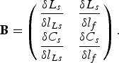 $${\bf B} = \left( {\matrix{ {\displaystyle{{\delta {L_s}} \over {\delta {l_{Ls}}}}} & {\displaystyle{{\delta {L_s}} \over {\delta {l_{f}}}}} \cr {\displaystyle{{\delta {C_s}} \over {\delta {l_{Ls}}}}} & {\displaystyle{{\delta {C_s}} \over {\delta {l_f}}}} \cr}} \right).$$
With this ASM scheme, the layout providing the target elements of the series branch is determined, and from this layout, the parasitic capacitance C par is also inferred. The value of C par is relevant since it must be subtracted to the capacitance C pi of the mirrored SIRs, as it will be justified later.
3) ASM applied to the mirrored SIRs
The layout of the mirrored SIRs is determined using an ASM algorithm with three variables. The variables in the optimization space are the elements of the shunt resonator from the circuit schematic for the common mode depicted in Fig. 1(d), i.e. x c = (L pi , Cpi, Czi ). The validation space is constituted by a set of variables defining the resonator layout. In order to deal with the same number of variables in both spaces, the widths of the central patch, W Czi , as well as the widths of the high- and low-impedance transmission line sections of the SIRs, W Lpi , and W Cpi , respectively, are set to fixed values. Thus, the variables in the validation space are the remaining dimensions of the shunt resonators, that is, the length of the central capacitive patch, l Czi , and the lengths l Lpi and l Cpi of the high- and low-impedance transmission line sections, respectively, of the SIR (i.e. x f = (l Lpi , lCpi, lCzi )). The specific procedure to determine the layout is similar to the one detailed in [Reference Sans, Selga, Rodríguez, Bonache, Boria and Martín20]. The first vector of the validation space, x f (1), is estimated from the well-known (and simple) approximate formulas providing the inductance and capacitance of a narrow and wide, respectively, electrically small transmission line section [Reference Pozar24]. Isolating the lengths, we obtain:
 $${l_{Lp}} = \displaystyle{{{L_p}{v_h}} \over {{Z_h}}},$$
 $${l_{Cp}} = {C_p}{v_{lp}}{Z_{lp}},$$
 $${l_{Cz}} = {C_z}{v_{lz}}{Z_{lz}},$$
where v h and v lp,z are the phase velocities of the high- and low-impedance transmission lines sections, respectively, and Z h and Z lp,z the corresponding characteristic impedances (note that the sub-indices p, z in the phase velocity, and characteristic impedance of the low-impedance transmission line sections are used to differentiate the central, C z, and external, C p, patches). Parameter extraction is carried out as specified in Section II. Finally, the first approach to the Broyden matrix, necessary to iterate the process, is given by:
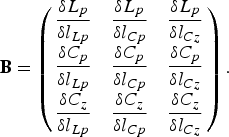 $${\bf B} = \left( {\matrix{ {\displaystyle{{\delta {L_p}} \over {\delta {l_{Lp}}}}} & {\displaystyle{{\delta {L_p}} \over {\delta {l_{Cp}}}}} & {\displaystyle{{\delta {L_p}} \over {\delta {l_{Cz}}}}} \cr {\displaystyle{{\delta {C_p}} \over {\delta {l_{Lp}}}}} & {\displaystyle{{\delta {C_p}} \over {\delta {l_{Cp}}}}} & {\displaystyle{{\delta {C_p}} \over {\delta {l_{Cz}}}}} \cr {\displaystyle{{\delta {C_z}} \over {\delta {l_{Lp}}}}} & {\displaystyle{{\delta {C_z}} \over {\delta {l_{Cp}}}}} & {\displaystyle{{\delta {C_z}} \over {\delta {l_{Cz}}}}} \cr}} \right).$$
With this ASM scheme, the layout providing the target elements of the shunt branch is determined, and from this layout, the parasitic capacitance L par is also inferred.
D) Strategy to determine the circuit schematic satisfying specifications
With the previous ASM algorithms, the layouts of the filter stages corresponding to the interdigital capacitors and mirrored SIRs can be determined. However, the presence of the parasitic elements forces us to recalculate the circuit schematic taking into account such parasitics. The hypothesis in the design process is to assume that once the parasitics are inferred, following the processes indicated above, the values do not significantly depend on the specific geometry. Hence, the next step is to set the element values of the parasitics to the inferred values, and consider the remaining elements as variables that must be tuned at the circuit level in order to satisfy the filter specifications. However, as long as the inductance L par is small, as it has been verified, one expects that by subtracting the parasitic capacitance C par to the capacitance of the mirrored SIR, C p , the variables in the optimization process do not need to be modified so much. Indeed, it has been verified that it is enough to tune L s to satisfy the filter specifications. Thus, by tuning this element, the final circuit schematic, including the parasitics, is determined. Therefore, the layout of the interdigital capacitors must be recalculated following the previous ASM algorithms. Then the resulting layouts are cascaded, and filter topology is thus constructed.
IV. ILLUSTRATIVE EXAMPLE
As an example, let us consider the synthesis of an order-3 Chebyshev filter with fractional bandwidth FBW = 40%, ripple L Ar = 0.15 dB, and central frequency f 0 = 2.4 GHz. The element values of the canonic circuit are: L s = 9.57087 nH, C s = 0.495948 pF, L p = 1.1637 nH, and C p = 3.77899 pF. The application of ASM to the interdigital capacitors provides the layout depicted in Fig. 3, and the element values are also depicted in the caption of Fig. 3 result. The error of this ASM process after convergence is 0.3%. For the shunt branch, we have reduced the value of the capacitance C par from C p , for the reasons explained before. The resulting layout by applying the explained ASM procedure is the one depicted in Fig. 2, and the element values are indicated in the caption. Less than 0.05% error has resulted in this case. Once the element values are inferred, we have tuned L s at the circuit level in order to recalculate the schematic, including parasitic that satisfies the specifications. The value of L s has been found to be: L s = 9.06 nH. Figure 4 shows a comparison between the ideal Chebyshev response, and the one of the optimized circuit schematic. As can be seen, the responses are very similar, thus validating the approach based on the tuning of L s only. Once the new value of L s is found, it is necessary to recalculate the new layout of the interdigital capacitor by applying the ASM algorithm explained before. This layout is depicted in Fig. 5 (dimensions are indicated in the caption), together with the frequency response. The resulting element values are L s = 9.0644 nH, C s = 0.4599 pF, C par = 0.2706 pF, and the error is smaller than 0.1%. Note that the parasitic capacitance C par has changed only slightly, as anticipated.
Comparison between the ideal Chebyshev response and the frequency response of the filter schematic including parasitic elements.

Final layout of the interdigital capacitors (a) and frequency response (b). Dimensions are (in mm): R w = 4.189, w f = 0.160, l Ls = 3.820, and l f = 0.718. The element values are: L s = 9.0644 nH, C s = 0.4599 pF, and C par = 0.2706 pF.

The layout of the final filter has been obtained by cascading the three stages. It is depicted in Fig. 6(a), whereas the photograph of the fabricated prototype is depicted in Fig. 6(b). The LPKF H-100 drilling machine has been used for the fabrication of the prototype. The frequency response of the filter, including the simulation of the optimum schematic, electromagnetic simulation, and measurement is depicted in Fig. 7. The agreement between the electromagnetic simulation and circuit simulation is reasonable, and discrepancies with the measurement can be attributed to fabrication-related tolerances. The maximum measured insertion loss for the differential mode is 0.8 dB between 1.90 and 2.85 GHz (FBW = 40%), whereas the return loss is higher than 14 dB within the same frequency range. The common-mode response is reasonably predicted by the circuit model, as depicted in Fig. 7(b). Common-mode rejection is better than 17 dB in the whole differential filter pass band with a maximum rejection of 58 dB at 2.5 GHz. Concerning dimensions, these are as small as 24.0 × 17.5 mm2, that is 0.48 × 0.35λ 2 (excluding the tapered access lines), λ being the guided wavelength at the central filter frequency.
Final layout of the filter (a) and photograph of the fabricated prototype (b). The dimensions are (in mm): W T = 24 and L T = 17.5.

Frequency response of the filter. Differential mode (a) and common mode (b). The measured unloaded quality factor is Q u (ω 0) = 79.84 [Reference Hong and Lancaster21].

For comparison purposes, we include a table (Table 1) where the size (effective area, expressed in terms of the square wavelength at the filter central frequency, f 0), and filter performance, including the −3 dB fractional bandwidth, common-mode rejection ratio at f 0, and differential-mode insertion loss at 2f 0, are provided. According to this table, where filters with fractional bandwidth of the same order are considered, the proposed filter exhibits a good balance between size and performance. However, the main relevant aspect of this paper is the fact that the filter has been designed following an unattended procedure.
Comparison of various differential filters.

V. CONCLUSIONS
In conclusion, novel wideband differential-mode microstrip bandpass filters with common-mode suppression, plus an automated synthesis method for such filters, based on ASM, have been presented in this paper. The filter has been described by means of lumped elements, and it has been demonstrated that the circuit model provides a good description of the filter response for both the differential- and common-modes. As compared with previous wideband balanced bandpass filters based on SIRs coupled through admittance inverters (in practice implemented by means of quarter-wavelength transmission line sections), the proposed filters are described (differential mode) by an equivalent circuit similar to the canonical model of a bandpass filter, where the circuit schematic is composed by reactive elements (inductances and capacitances). However, the circuit model includes parasitic elements, and the design process takes into account these elements. By replacing the inverters of previous implementations (e.g. [Reference Sans, Selga, Vélez, Rodríguez, Boria and Martín19]) with interdigital capacitors, a clear improvement in terms of filter size is achieved. But also in terms of circuit design, since the ASM-based synthesis method of these filters utilizes only one iterative step (rather than two) for the determination of the filter layout from the circuit schematic. It is remarkable that filter design follows an unattended scheme, where the layout is generated from the required Chebyshev (differential-mode) response. The specific ASM synthesis tool has been explained in detail and then it has been applied to the synthesis of an order-3 balanced bandpass filter with common-mode suppression. The obtained results have pointed out the efficiency of the iterative algorithm (3 and 11 iterations are necessary to generate the layout of the SIR and interdigital capacitor stages, respectively) and the small size of the resulting prototype (achieved by virtue of the use of interdigital capacitors for the series branches). This iterative process means a CPU effort of approximately 35 min (using a Intel®Core™ with 8 GB of RAM and a 2.86 GHz clock processor). Moreover, the characterization results indicate that these filters provide significant common-mode suppression in the differential filter pass band.
ACKNOWLEDGEMENTS
This work was supported by MINECO-Spain (projects no. TEC2013-47037-C5-1-R, TEC2013-40600-R, and TEC2013-49221-EXP), Generalitat de Catalunya (project no. 2014SGR-157), and Institució Catalana de Recerca i Estudis Avançats (who has awarded Ferran Martín).
 Marc Sans was born in Terrassa (Barcelona), Spain, in 1982. He received the B.S. degree in Telecommunications Engineering – Electronic Systems in 2006, the M.S. degree in Telecommunications Engineering in 2008, and the M.S. degree in Electronics Engineering in 2013 from the Universitat Autònoma de Barcelona (UAB). In 2008, he started his professional career as a RF Engineer at Sony-FTVE developing the RF stage of TV receivers. In 2010, he moved to Mier Comunicaciones S.A. to carry out the design of passive and active devices for VHF-UHF broadcasting units. Since 2014, he is working toward the Ph.D. degree at CIMITEC-UAB in the synthesis of microwave devices based on EM optimization techniques.
 Jordi Selga was born in Barcelona, Spain, in 1982. He received the B.S. degree in Telecommunications Engineering – Electronic Systems in 2006, the M.S. degree in Electronics Engineering in 2008, and the Ph.D. degree in Electronics Engineering in 2013 from the Universitat Autònoma de Barcelona (UAB), Barcelona, Spain. Since 2008 he is a member of CIMITEC-UAB, a research center on Metamaterials supported by TECNIO (Catalan Government). He was holder of a national research fellowship from the Formación de Profesorado Universitario Program of the Education and Science Ministry (Reference no. AP2008-4707). He is currently working in subjects related to metamaterials, CAD design of microwave devices, EM optimization methods, and automated synthesis of planar microwave components at the UAB.
 Paris Vélez was born in Barcelona (Spain) in 1982. He received the degree in Telecommunications Engineering, specializing in Electronics in 2008 and the Electronics Engineering degree in 2010 from the Universitat Autònoma de Barcelona (UAB). In 2014, he received his Ph.D. in Electrical Engineering from the UAB with a thesis entitled “Common mode suppression differential microwave circuits based on Metamaterial concepts and semilumped resonators”. During the Ph.D. he was awarded with a predoctoral teaching and research fellowship by the Spanish Government from 2011 to 2014. Dr. Vélez is a reviewer of the IEEE T-MTT and of other journals. Actually, his scientific activity is focused on the miniaturization of passive circuits RF/microwave based Metamaterials.
 Ana Rodriguez was born in Lugo, Spain. She received the Telecommunications Engineering degree from the Universidade de Vigo (UV), Spain, in 2008. As a student, she participated in the Erasmus exchange program, developing the Master Thesis at the University of Oulu, Finland. Since the end of 2008, she has joined the Institute of Telecommunications and Multimedia Applications (iTEAM), which is part of the scientific park at the Universitat Politècnica de València (UPV), Spain. She obtained “Master en Tecnología, Sistemas y Redes de Comunicaciones” in 2010 from UPV, and the Ph.D. degree in 2014. Her main research interests include CAD design of microwave devices, EM optimization methods, and metamaterials.
 Jordi Bonache was born in 1976 in Barcelona (Spain). He received the Physics and Electronics Engineering degrees from the Universitat Autònoma de Barcelona (UAB) in 1999 and 2001, respectively and the Ph.D. degree in Electronics Engineering from the same university in 2007. In 2000, he joined the “High Energy Physics Institute” of Barcelona (IFAE), where he was involved in the design and implementation of the control and monitoring system of the MAGIC telescope. In 2001, he joined the Department of Electronics Engineering of the UAB where he is currently a Lecturer. From 2006 to 2009 he worked as an executive manager of CIMITEC. Currently is leading the research in RFID and antennas in CIMITEC. His research interests include active and passive microwave devices, metamaterials, antennas, and RFID.
 Vicente E. Boria was born in Valencia, Spain, on May 18, 1970. He received his “Ingeniero de Telecomunicación” degree (with first-class honors) and the “Doctor Ingeniero de Telecomunicación” degree from the Universidad Politécnica de Valencia, Valencia, Spain, in 1993 and 1997, respectively. In 1993, he joined the “Departamento de Comunicaciones”, Universidad Politécnica de Valencia, where he has been Full Professor since 2003. In 1995 and 1996, he was holding a Spanish Trainee position with the European Space Research and Technology Centre, European Space Agency (ESTEC-ESA), Noordwijk, The Netherlands, where he was involved in the area of EM analysis and design of passive waveguide devices. He has authored or co-authored ten chapters in technical textbooks, 135 papers in refereed international technical journals, and over 180 papers in international conference proceedings. His current research interests are focused on the analysis and automated design of passive components, left-handed and periodic structures, as well as on the simulation and measurement of power effects in passive waveguide systems.
Dr. Boria has been a member of the IEEE Microwave Theory and Techniques Society (IEEE MTT-S) and the IEEE Antennas and Propagation Society (IEEE AP-S) since 1992. He is reviewer of the IEEE Transactions on Microwave Theory and Techniques, Proceeding of the IET (Microwaves, Antennas and Propagation) and IET Electronics Letters. Since 2013, he serves as an Associate Editor of IEEE Microwave and Wireless Components Letters. He is also a member of the Technical Committees of the IEEE-MTT International Microwave Symposium and of the European Microwave Conference.
 Ferran Martín received the B.S. degree in Physics from the Universitat Autònoma de Barcelona (UAB) in 1988 and the Ph.D. degree in 1992. From 1994 up to 2006, he was an Associate Professor in Electronics at the Departament d'Enginyeria Electrònica (Universitat Autònoma de Barcelona), and since 2007 he is a Full Professor of Electronics. In recent years, he has been involved in different research activities, including modeling and simulation of electron devices for high-frequency applications, millimeter wave and THz generation systems, and the application of electromagnetic bandgaps to microwave and millimeter wave circuits. He is now very active in the field of metamaterials and their application to the miniaturization and optimization of microwave circuits and antennas. He is the head of the Microwave Engineering, Metamaterials and Antennas Group (GEMMA Group) at UAB, and director of CIMITEC, a research Center on Metamaterials supported by TECNIO (Generalitat de Catalunya). He has organized several international events related to metamaterials, including Workshops at the IEEE International Microwave Symposium (years 2005 and 2007) and European Microwave Conference (2009), and the Fifth International Congress on Advanced Electromagnetic Materials in Microwaves and Optics (Metamaterials 2011), where he has acted as chair of the Local Organizing Committee. He has acted as Guest Editor for three Special Issues on Metamaterials in three International Journals. He has authored and co-authored over 450 technical conference, letter, journal papers, and book chapters; he is co-author of the book on Metamaterials entitled Metamaterials with Negative Parameters: Theory, Design and Microwave Applications (John Wiley & Sons Inc. 2008), author of the book Artificial Transmission Lines for RF and Microwave Applications (John Wiley & Sons Inc. 2015), and he has generated 15 Ph.D.s. Ferran Martín has filed several patents on metamaterials and has headed several Development Contracts.
Prof. Martín is a member of the IEEE Microwave Theory and Techniques Society (IEEE MTT-S). He is a reviewer of the IEEE Transactions on Microwave Theory and Techniques and IEEE Microwave and Wireless Components Letters, among many other journals, and he serves as a member of the Editorial Board of IET Microwaves, Antennas and Propagation and International Journal of RF and Microwave Computer-Aided Engineering. He is also a member of the Technical Committees of the European Microwave Conference (EuMC) and International Congress on Advanced Electromagnetic Materials in Microwaves and Optics (Metamaterials). Among his distinctions, Ferran Martín has received the 2006 Duran Farell Prize for Technological Research, he holds the Parc de Recerca UAB – Santander Technology Transfer Chair, and he has been the recipient of two ICREA ACADEMIA Awards (calls 2008 and 2013). He is an IEEE Fellow since 2012.



