Introduction
Manufacturing of geometrically complex components requires expensive tooling and extensive machining, which may result in nearly 80% of material as waste.[Reference Christensen, Kricher and Lippincott1, Reference Rawal, Brantley and Karabudak2] With advances in additive manufacturing, also known as three-dimensional printing, precursor metallic powder has been increasingly used to produce near-net shape, complex metallic components using layer-by-layer additive manufacturing techniques.[Reference Huang, Leu, Mazumder and Donmez3]
Generally, additive manufacturing of metallic components can be classified into two categories: powder bed fusion-based and directed energy deposition-based. For powder bed fusion techniques, an electron beam or high-power laser is utilized to selectively sinter/melt metallic powder that has been previously raked across a stage, resulting in a structure after cooling. For directed energy deposition techniques, a laser is used to produce a melt pool on a wrought substrate, and metallic powder is simultaneously injected into the melt pool, forming a structure after solidification. Although it is recognized that there are various inherent defects with additively manufactured/printed metallic components such as porosity, thermal residual stress, and microstructure gradients, they have found extensive use in the healthcare (knee and hip[Reference Murr, Gaytan, Medina, Martinez, Hernandez, Martinez, Lopez, Wicker and Collins4, Reference Murr, Quinones, Gaytan, Lopez, Rodela, Martinez, Hernandez, Martinez, Medina and Wicker5] and dental[Reference Joshi, Duan, Neidigh, Koike, Chahine, Kovacevic, Okabe and Griggs6] implants), aviation (support bracket for spacecrafts[Reference Rawal, Brantley and Karabudak2]), and automotive (tooling dies[Reference Cormier, Harrysson and West7]) industries. Some printing-induced defects can be minimized or mitigated using post-printing procedures such as hot isostatic pressing (HIP). Although additively manufactured metallic components are often printed as near-net shape, their surface roughness still prevents them from immediate use in industry. Therefore, finish machining is required to improve the surface roughness and bring components to their final dimensions.
The objective of this study is to investigate the grain size variation and saw-tooth/shear-band spacing during the machining of titanium alloy (Ti–6Al–4V) printed using direct metal deposition (DMD), which may help understand the post-machining part quality of additively manufactured parts as well as evaluate their dynamic behavior. While different process-induced material property challenges of additively manufactured parts can be overcome by using post-processing heat treatments such as HIP or process optimization, the microstructure variation, and material dynamic behavior during machining is largely ignored. It is generally known that the microstructure of metals, including titanium and its alloys influences their yield stress, ductility, and performance.[Reference Rotella, Dillon, Umbrello, Settineri and Jawahir8] As such, the grain size of machined workpieces is of primary interest to industry. In addition, the material dynamic behavior of additively manufactured components should be standardized with those of wrought metals to enable broader high strain-rate applications. Unfortunately, both the machining-induced microstructure variation and the material dynamic behavior of additively manufacturing metallic parts have not been examined. In this study, the microstructure variation is evaluated in terms of the grain size of machined surfaces, and the dynamic behavior is characterized based on the machining-induced saw-tooth spacing, which is an index of high strain-rate deformation behaviors and failure of structural components.
Materials and method
Workpiece preparation using DMD
Ti–6Al–4V was selected for its low weight, high strength, and high corrosion resistance, which make it a versatile material in the automotive, aerospace, and medical industries. Ti–6Al–4V components examined in this study were fabricated using DMD,[Reference Bao, Newkirk, Ruan, Sparks and Liou9] a directed energy deposition-based additive manufacturing technique. During DMD, as shown in Fig. 1, a laser is used to produce a melt pool on a wrought Ti–6Al–4V substrate. Metallic powder is simultaneously fed into the melt pool where it solidifies to form a pattern or layer as designed. The process is continuous and produces structures layer-by-layer until a build is complete.
Schematic representation of DMD process and finished component.

Generally, commercially pure titanium may change from the hexagonal close-packed (hcp) structure (α phase) to the body-centered cubic structure (β phase) at 882.5 °C. The α to β transformation temperature is affected by alloying elements, resulting in α, β, and/or α + β equilibrium phases. For Ti–6Al–4V, the β transus temperature is 980 °C.[Reference Donachie10] Such an α to β transformation temperature may be affected by alloying elements, primarily aluminum, which acts as an α stabilizer, resulting in an increase in the β transus, and vanadium, which acts as a β stabilizer, resulting in the decrease of the β transus.[Reference Donachie10, Reference Saxena and Radhakrishnan11] During processing, upon cooling from the β transus, martensite may from if the cooling rate is sufficiently high. The martensite structure is metastable; therefore, further solution annealing or aging is required. Solution annealing is most often done at a temperature that is 25–85 °C below the β transus, while aging is usually done between 400 and 600 °C. Aging results in the diffusionless transformation of the martensitic into α phase. As a result of the heat treatment temperatures used, heat transfer through the material may alter the microstructure within the component, primarily resulting in grain growth. After cooling, this grain growth can be retained where the cooling rate and heat treatment duration determine the extent of grain growth.[Reference Donachie10] Analogous to the effect of heat treatment, machining-induced heat may also introduce microstructure alterations to certain metals such as severe plastic deformation (SPD)-processed copper.[Reference Huang and Morehead12]
Figure 2 shows an as-printed Ti–6Al–4V structure as well as its resulting microstructures at two different locations within the printed region (Locations A and B) and the substrate (Location C). The microstructures at Locations A and B consist of the basket-weave Widmanstätten α phase (white) outlined in the β phase (dark). The characteristics of basket-weave structures have α platelets that cross and overlap each other as a basket-weave pattern. It should be noted that the microstructure can also have a colony Widmanstätten α morphology.[Reference Bao, Newkirk, Ruan, Sparks and Liou9] The microstructure of the as-printed structure is used as the control for grain size comparison with respect to that of the printed region after machining. The substrate region, represented as Location C in Fig. 2, is found to be a bimodal (showing globular α grains and equiaxed α + β structure) microstructure consisting of α phase delineated by the β phase at grain boundaries. This microstructure is characteristic of wrought Ti–6Al–4V and is used as the control for overall grain size comparison after machining.
Printed DMD Ti–6Al–4V structure with microstructures at different locations shown in insets (α phase in white, β phase in black, and the scale bar is 10 μm).
Within the structure, it is observed that the initial grain size changes throughout the build height with smaller, finer grains at the bottom (close to the substrate) and larger, coarser grains at the top. The grain sizes observed throughout the build height are: 1.78 ± 0.23 μm at Location A, 1.51 ± 0.36 μm at Location B, and 15.36 ± 1.16 μm at Location C. Wu et al.[Reference Wu, Liang, Mei, Mitchell, Goodwin and Voice13] reported a similar trend during the laser engineered net shaping of Ti–6Al–4V and attributed it to the influence of the substrate, which acts as a heat sink, resulting in a finer grain size due to a rapid cooling rate for previously printed layers close to the substrate. Similar phenomenon was observed in the laser depositing of AISI 4340 steel,[Reference Bhattacharya, Dinda, Dasgupta and Mazumder14] where previously printed layers were assumed as a heat sink for subsequent layers. However, it has also been hypothesized that subsequent laser passes result in the annealing of previously printed layers, so the microstructure has more time to nucleate and grow at the bottom of the structure than in other regions, producing a coarser grain size.[Reference Fu, Fan, Pulugurtha, Sparks, Ruan, Liou and Newkirk15]
Machining setup
Owing to the shape of the DMD printed structures, the workpiece samples were first cast in a machinable urethane (BCC Products, Inc., Franklin, IN) to ensure rigidity during machining. Two milling configurations were adopted: end and peripheral milling. End milling was used to study the change in grain size as a result of machining, whereas peripheral milling was implemented to investigate the saw-tooth/shear-band spacing during machining.
The machining processes were conducted on a MIKRON UCP 600 Vario 5-axis milling center (GF Agie Charmilles, Switzerland), and all machining experiments were carried out under dry cutting conditions to eliminate unnecessary cooling effects. The cutting conditions used in this study were cutting speed V = 2 m/s, feedrate f = 0.05 mm/rev, and depth of cut DOC = 0.1 mm, which are representative finishing conditions for titanium alloys. The cutting tools were 0.25 inch diameter (end milling) and 0.50 inch diameter (peripheral milling) carbide five-flute end mills (MA FORD, Valdosta, GA).
Characterization of grain size and saw-tooth/shear-band spacing
The grain size was measured at the machined surface corresponding to Locations (A), (B), and (C) as shown in Fig. 2. Both the unmachined and machined components were polished using 300, 600, 800, 1000, and 1200-grit silicon carbide sand paper (Allied High Tech Products, Inc., Rancho Dominguez, CA), followed by polishing in a 0.3 μm diamond solution (Pace Technologies, Tucson, AR) and a 0.05 μm colloidal silica solution (Pace Technologies, Tucson, AR) sequentially until a mirror finish is achieved. Then the samples were chemically etched in Kroll's reagent (2 mL HF, 6 mL HNO3, and 92 mL deionized water) for approximately 10 s. The grain size of the substrate was measured using the intercept method using the ASTM standard E112-13, since it is the most repeatable and efficient. For the printed region, only α platelet width was measured and reported herein since measuring the length of the α phase would produce many inconsistencies due to the nature of the overlapping basket-weave structure.
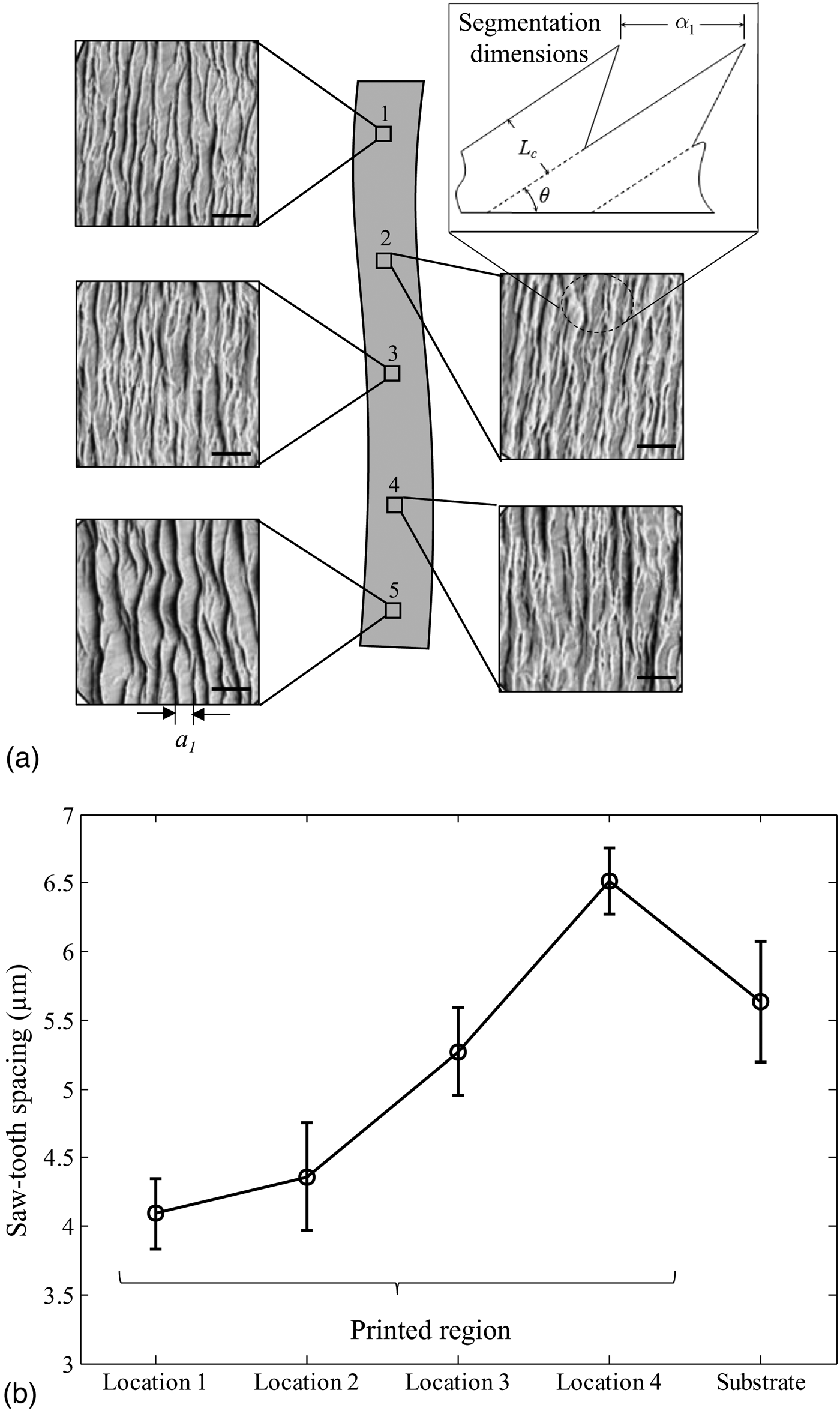
Saw-tooth spacing, typically observed during the machining of titanium and its alloys, was studied by observing machined chips. To study the spacing variation, the free surface of machined chips was analyzed at five difference locations along the axial direction of the structure as show in Fig. 3(b). The saw-tooth spacing was first measured by averaging ten spacing measurements along the chip flow direction. The shear-band spacing can be found by multiplying the saw-tooth spacing value by sinθ, where θ is the crack initiation angle.[Reference Morehead, Huang and Luo16] For simplicity, the crack initiation angle is assumed constant, so the saw-tooth spacing is assumed to represent the shear-band spacing in this study.
Experimental setup: (a) end and (b) peripheral milling configurations.
Effects of machining on grain size and saw-tooth spacing
Grain size variation
Grain size variations, due to machining-induced high-temperature and high strain-rate deformation, of the machined workpiece surface as well as resulting chips have been well recognized as two main possibilities: grain coarsening[Reference Huang and Morehead12] or grain refinement[Reference Akcan, Shah, Moylan, Chhabra, Chandrasekar and Yang17, Reference Arisoy and Ozel18]. Grain coarsening may be due to the grain growth of ultrafine or nanostructured grains of thermally metastable materials such as SPD-processed metals. Grain refinement can be the result of deformation twinning[Reference Shankar, Rao, Lee, Chandrasekar, King and Compton19] due to the SPD (large strain) and/or dynamic recrystallization[Reference Meyers, Subhash, Kad and Prasad20, Reference Andrade, Meyers, Vecchio and Chokshi21] caused by the high strain-rate experienced inside the shear zone.
As shown in Fig. 4(a), the grain size after machining is observed to reduce to 1.46 ± 0.12, 1.09 ± 0.18, and 9.25 ± 0.78 μm for Locations A, B, and C, respectively. The grain structures of the printed and substrate regions have retained the basket-weave and bimodal structures, respectively, giving no indication of phase transformation occurring during machining. In particular, the substrate region experienced the most significant grain refinement in terms of both the absolute and relative values (30% versus 35% versus 47%) as shown in Fig. 4(b). The mechanism for the observed grain refinement may be attributed to deformation twinning and/or dynamic recrystallization. Some hcp materials such as titanium can only withstand so much deformation through slip and are prone to deformation twinning up to a critical dislocation density; after this critical value is reached, the conditions are favorable for dynamic recrystallization. Deformation twinning was observed during the machining of commercially pure titanium[Reference Shankar, Rao, Lee, Chandrasekar, King and Compton19]; however, due to the low cutting speed used (10 mm/s), the critical strain for the onset of dynamic recrystallization may not have been reached. In this study, while no twinning is observed using scanning electron microscopy, the strain-rate ( $\dot \gamma $ induced by V = 2 m/s) may have been sufficient to trigger the onset of dynamic recrystallization, resulting in refined grains for both the printed and substrate regions. This twinning-related observation will be further validated using transmission electron microscopy (TEM) in future studies. As such, dynamic recrystallization and subsequent grain growth[Reference Rotella, Dillon, Umbrello, Settineri and Jawahir8] are considered as the grain variation mechanism. The resultant grain refinement indicates that the effect of dynamic recrystallization overshadows that of subsequent grain growth due to machining-induced heating. It should be noted that different microstructures may form under different cooling rates after machining. When Ti–6Al–4V is heated and cooled from the β region, it exhibits a transformed microstructure depending on the cooling rate. When the cooling rate is high, a martensitic structure or fine Widmanstätten structure is formed, and the martensitic structure may be further decomposed into an α/β Widmanstatten structure upon further heat treatment. When the cooling rate is lower, it is usual to form a coarse Widmanstätten structure composed of primary α with retained or transformed β at the grain boundaries.[Reference Donachie10, Reference Blenkinsop, Lütjering, Zwicker and Bunk22] As such, the cooling rate may also play an important role in determining the final grain size.
(a) Change in grain size and (b) percent difference.
Saw-tooth spacing alteration
Figure 5(a) illustrates the measurement locations and corresponding images of the saw-tooth spacing (a 1) of a representative chip generated under the peripheral milling configuration as shown in Fig. 3(b). Figure 5(b) shows the saw-tooth spacing for the five different locations measured from the top of the printed region to the substrate, and the measurement values are 4.09 ± 0.26, 4.36 ± 0.39, 5.27 ± 0.32, 6.51 ± 0.24, and 5.63 ± 0.44 μm for Locations 1 to 5, respectively.
(a). Schematic representation showing the five measurement locations and representative chip surfaces (the scale bar is 5 μm and the inset is about segmentation dimensions) and (b) saw-tooth spacing measurements.
It is found that the saw-tooth spacing decreases along the axial direction of the chip from the bottom (Location 4, with the smallest grain size) to the top (Location 1, with the largest grain size) of the printed region. The observed saw-tooth spacing difference is attributed to the difference in grain size at different locations of the printed region. Metals with a smaller grain size usually have a higher Young's modulus and larger hardness. As a result, it may store more elastic energy before plastic deformation is initiated, resulting in a delay in the onset of subsequent shear localization, resulting in a larger saw-tooth spacing [and shear-band spacing (L c) consequently as shown in the Fig. 5(a) inset] under the same cutting conditions. It should be pointed out that the location with the largest grain size, Location 5 (substrate) in Fig. 5(a), the saw-tooth spacing is smaller than that at Location 4 because of possible differences in shear localization mechanisms for a metal with different grain structures (bimodal versus basket-weave). By assuming a constant crack initiation angle, the conclusion regarding the saw-tooth spacing can be extended to the shear-band spacing accordingly since L c = a 1sinθ. As such, it is concluded that the shear-band spacing decreases along the axial direction of the chip from the bottom to the top of the printed region.
Conclusions and future work
Additive manufacturing has emerged as a competitive technology for the fabrication of metallic components, which have mechanical properties that may be comparable or even exceed those prepared using conventional technologies such as casting. This study has investigated the grain size variation and saw-tooth/shear-band spacing during the machining of Ti–6Al–4V printed using DMD. The findings are expected to promote the optimization and adoption of additively manufactured metallic components. Some main conclusions are drawn as follows:
1. There is an observable grain refinement of both the printed and substrate regions, and the grain structures of the printed and substrate regions have retained the basket-weave and bimodal structures, respectively. Dynamic recrystallization is assumed as the grain refinement mechanism in this study; and
2. The saw-tooth spacing decreases along the axial direction of the chip from the bottom to the top of the printed region.
Some future work is expected to further validate and explain the observed variations of grain size and saw-tooth/shear-band spacing of additively manufactured metallic components after machining, in particular, using some analysis and analytical tools such as TEM, x-ray diffraction, and electron backscatter diffraction (EBSD). First, TEM is to be adopted to observe dislocations within single grains to determine whether deformation twinning or dynamic recrystallization is the primary grain refinement mechanism for the printed region. This will help determine the existence of fine recrystallized Widmanstätten grains and the dislocation morphology around grain boundaries. Second, x-ray diffraction should be used to determine whether a diffusionless phase transformation occurs at grain boundaries during machining of titanium and titanium alloys. Third, EBSD may be used to determine misorientation angles of grain boundaries as well as the grain texture. The use of EBSD, coupled with TEM results, may help determine the onset of dynamic recrystallization. Fourth, cross-sectional images of chips may be taken to better understand the onset of shear localization within additively manufactured structures after machining. Finally, more cutting conditions may be applied to machine workpieces with different initial microstructures to draw more general conclusions regarding cutting forces and machinability.
Acknowledgments
The study is partially supported by the NSF (CMMI-1404926). The authors would like to acknowledge Felipe Barbosa, Christa Torrence, and Dr. Nancy Ruzycki of the University of Florida for their sample preparation and microscopy assistance.