1. INTRODUCTION
In the domain of global navigation satellite systems (GNSS), compatible implies that the interference between GNSSs does not exceed a well-defined threshold and thus a degradation of the positioning accuracy due to interference can be excluded (Hein, Reference Hein2006, Wallner, 2006). Along with the evolvement of GNSS and augmentation systems, the number of satellites and signals being deployed increases rapidly with all signals sharing limited available radio frequency bands. As a result, inter-system interference between different GNSSs becomes more severe. Therefore compatibility assessment methodology and signal design based on radio frequency compatibility has become a widely focused issue.
In April, 2011, the eighth Compass Phase II (CP II) satellite was launched by China, which will provide positioning, navigation, timing and communication services to the Asia-Pacific region before 2012 (Xinhua News, 2011). It is necessary to assess the radio frequency compatibility between CP II and all other GNSSs, such as GPS, GLONASS, Galileo, Wide Area Augmentation System (WAAS) and European Geostationary Navigation Overlay Service (EGNOS). The interference assessment results of CP II will be useful for system providers and user communities. The assessment results also serve the purpose of being a design reference for the Compass phase III (CP III) system.
Previous research on compatibility assessments between GPS and Galileo is introduced in references (Betz, Reference Betz2001, Godet, 2002, Wallner, 2006), and some of the methodologies for the GNSS compatibility analysis are developed in these papers. The spectral separation coefficient (SSC) (Betz, Reference Betz1999) is presented to assess the impact of interfering signals on the processing phases of the receiver's prompt correlator channel. Then the theory of the effective carrier-power-to-noise density ratio (C/N 0)eff that assesses the effect of interfering signals on the GNSS receiver is introduced (Betz, Reference Betz2001). Furthermore, the theory of code tracking spectral sensitivity coefficient (CT_SSC) that evaluates the interference level on a code tracking loop is also presented (Soualle, 2007b). Other important factors, such as the Doppler offset, code tracking loop and band-limiting, sampling and quantization (BSQ) of GNSS receivers, have not been taken into account in the compatibility assessments. This paper introduces a modified compatibility assessment methodology that covers the influence of the mentioned factors which are ignored by traditional methodologies. Interference between CP II and other GNSSs will be calculated using this modified compatibility assessment methodology. All signals on L1 band, which include (i) CP II B1I and B1Q signal, (ii) GPS L1CA, L1P, L1M and L1C signals, (iii) Galileo E1OS and E1PRS signals, (iv) WAAS L1 signal, and (v) EGNOS L1 signal, will be assessed in the simulation.
This paper is organised as follows: In section 2, the traditional parameters (C/N 0)eff and SSC for compatibility assessment are analysed. Section 3 of this paper analyses the effect of Doppler offset, code tracking loop and BSQ of GNSS receivers on the compatibility assessment, and introduces a modified methodology that takes into account the effect of all these factors. In section 4, the simulation results of compatibility assessment between CP II and other GNSSs, such as GPS, Galileo, WAAS and EGNOS, are given respectively. Conclusions are drawn in section 5.
2. TRADITIONAL METHODOLOGIES OF COMPATIBILITY ASSESSMENT
2.1. Spectral separation coefficient
The SSC is presented as a relevant index to assess the impact of interfering signals on the processing phases of the receiver's prompt correlator channel which includes acquisition, carrier phase tracking and data demodulation. This is an appropriate index to assess how the power spectral densities (PSD) of two different signals are overlapped. Therefore the SSC can be used to access the compatibility of these two signals conveniently. The SSC is expressed as:
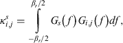
where κ i,js is the SSC between the desired signal and the j-th signal from the i-th satellite, G s(f) is the normalised PSD of the desired signal, G i,j(f) is the normalised PSD of the j-th interfering signal from the i-th satellite and β r is the receiver's front-end bandwidth.
In most articles, the SSC is considered as a constant, but this is not always true. In the following section, the phenomenon of a non-constant SSC will be described in detail, and a modified methodology will be proposed.
2.2. Effective carrier-power-to-noise density ratio
In order to quantify the effect of interference on characteristics at the input of a generic receiver, the parameter (C/N 0)eff is presented. The (C/N 0)eff parameter can be interpreted as the carrier-power-to-noise density ratio caused by an equivalent white noise that would yield the same correlation output variance obtained in the presence of an interfering signal (Soualle, 2007a). The parameter (C/N 0)eff is expressed as:
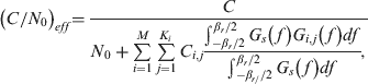
where C is the received power of the desired signal, N 0 is the PSD of the thermal noise, M is the number of visible satellites, K i is the number of signals transmitted by the i-th satellite and C i,j is the received power of the j-th interfering signal from the i-th satellite.
The most important component in expression (2) is the aggregate equivalent noise power density of interference that can be defined as the parameter I which is given by expression (3).
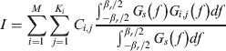
3. MODIFIED METHODOLOGIES OF COMPATIBILITY ASSESSMENT
3.1. Effect of Doppler offset
The effect of Doppler offset on compatibility computation is analysed, and a modified calculation methodology of (C/N 0)eff is given in this section. Doppler offset is the change in frequency of a signal that occurs as a result of the source and the observer moving relative to each other. When a ground receiver listens to the signal transmitted from a non-geostationary satellite, the relative movement will cause a frequency offset. The SSC shall then be expressed as expression (4) instead of expression (1) when Doppler offset exists.
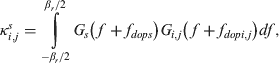
where f dops is the Doppler offset of the desired signal, and f dopi,j is the Doppler offset of the j-th interfering signal from the i-th satellite.
The characteristic of the SSC depend on the PSD of the navigation signal which is the key component used to calculate the SSC. The PSD of the navigation signal using periodical pseudo random codes with data modulation can be expressed as (Soualle, 2003):

where T c=1/ f c is one code-chip duration, f c is the code-chip rate, c k is the pseudo random codes sequence, φ(t) is the pulse shape associated to the spreading codes c k, DFT denotes the Discrete Fourier Transform, Φ(f) is the DFT of φ(t), f d is the data rate of navigation signal, T d=1/ f d is the duration of one navigation data bit and L is the code length.
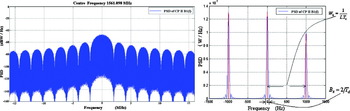
Taking the CP II B1I signal with a code-chip rate of 2·046 MHz, a code length of 2046 and a data rate of 50 sps as an example, the PSD of CP II B1I signal is shown in Figure 1 where the left hand side is the overview of PSD, while the right hand side is the zoomed in detailed view of PSD curve without applying a logarithmic operation. Because CP II B1I is a typical short-code signal, its PSD shows a line spectrum characteristic which is shown clearly in the right half part of Figure 1. As the SSC is defined as the inner product of the PSD between the desired and interfering signal, the line spectrum of short-code will cause a non-constant SSC.
PSD of CP II B1I signal. (Left) PSD of CP II B1I signal. (Right) Detail of CP II B1I signal's PSD without logarithm operation.

Since the mainlobe value in the right half part of Figure 1 is far more significant than its sidelobes, the influence of the sidelobes can be ignored. The condition that the line spectrum will disappear is expressed as follow (Liu, L., 2010):

where B z is the mainlobe width of the PSD of navigation data, and W k is the spectral lines interval of the PSD of navigation data with periodical pseudo random codes. B z is equal to 2/f d which is attributed to the nature of the sin c function, and W k is equal to 1/LT c according to expression (5). Then, following expression is derived as:

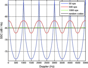
The SSC of the CP II B1I signal is shown with blue curve in Figure 2. The real value of the SSC changes in a periodical wave form along with the changes of the Doppler offset. The difference of 21·8 dB between the real and the ideal SSC at their peak value is because the pseudo random codes are repeated 20 times during a navigation bit time period which lasts for 20 ms.
SSC of CP II B1I signal for different data rate.

The SSC of a navigation signal with ideal random codes is shown by the black curve in Figure 2, which is a constant value calculated using the PSD of the code-chip instead of the signal's PSD. The expressions of the code-chip PSDs of Binary Phase Shift Keying (BPSK) and the Binary Offset Carrier (BOC) are given as below (Soualle, 2007a).
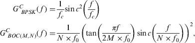
where f 0 is equal to 1·023 Mcps, N×f 0 is the code-chip rate, and M×f 0 is the sub-carrier frequency of the BOC pulse shape.
As we can see from Figure 2, the amplitude of periodical wave decreases when the data rate increases from 50sps to 500sps, to 1000sps. Once the condition L⩾f c/ fd is satisfied, the SSC converges to a constant value which is the SSC value of the navigation signal with ideal random codes. For the navigation signal with ideal random codes, it is reasonable to use the code-chip PSD instead of signal's PSD to calculate the SSC (Liu, L., 2010). The modified (C/N 0)eff can thus be presented here:
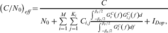
where GC s(f) is the code-chip PSD of the desired signal, and GC i,j(f) is the code-chip PSD of the interfering signal. When the navigation signals comply with the condition L⩾f c/ fd, IDop is estimated to be zero. Otherwise, I Dop is the maximum effective white noise PSD due to the difference between the maximum value of the real SSC and the SSC with ideal random codes.
3.2. Code tracking spectral sensitivity coefficient
The parameter SSC is appropriate to assess the impact of interfering signals on the processing phases of the receiver's prompt correlator channel, but not appropriate to evaluate the impact on code tracking loop phase. For this reason, a parameter called CT_SSC is presented by Soualle to assess the impact of interfering signals on the code tracking loop phase, in which the effect of early-to-late spacing of the correlator is considered (Soualle, 2007a, Liu, W., 2010). The CT_SSC is defined as:

where Δ the two-sided early-to-late spacing of the correlator.
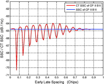
Figure 3 shows both the SSC and the CT_SSC of the CP II B1I signal. The oscillating seen on the CT_SSC curve is due to the additional term sin2(πfΔ) in the CT_SSC expression. The impact of interfering signals on a receiver's code tracking loop phase can be quantified and assessed by CT_SSC conveniently.
SSC and CT_SSC of CP II B1I signal.

Furthermore, a parameter effective carrier-power-to-noise density ratio with CT_SSC, denoted as (C/N 0)eff_CT_SSC, is introduced. The (C/N 0)eff_CT_SSC can be expressed as:

When Doppler offset is considered, the (C/N 0)eff_CT_SSC can be rewritten in further as:

Compatibility calculations using expression (12) could cover the impact of the Doppler offset and code tracking loop which are ignored in traditional methodologies.
3.3. Band-limiting, sampling and quantisation
Previous research indicates that a receiver's quantisation causes SNIR losses (Chang, Reference Chang1982). More comprehensive research of BSQ is provided by Betz (Betz, 2007). Nevertheless, the effect of BSQ loss on the assessment of GNSS radio frequency compatibility is ignored in traditional (C/N 0)eff methodologies. In this section, the effect of BSQ on the received power of navigation signals is discussed and is included in the improved (C/N 0)eff calculation. The signal power loss caused by BSQ of GNSS receivers could be presented as (Hegarty, 2010):
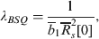
where  is related to the unity power gain of quantiser, here,
 is the first term of the sequence ,
 is the autocorrelation of desired signal, and the term
 is calculated by expression (14).
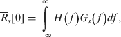
where H is the transfer function of the band-limiting filter. In general, the transfer function with an ideal filter is assumed to be 1.
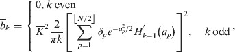
where  is a normalising constant related to the input-output characteristics of the quantiser, N is the level of the quantiser, δ p and a p are the characteristic parameters of the uniform step quantiser and H′ is a k-th order Hermite polynomial divided by
 . Here, the input of the quantiser is defined as:
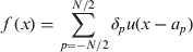
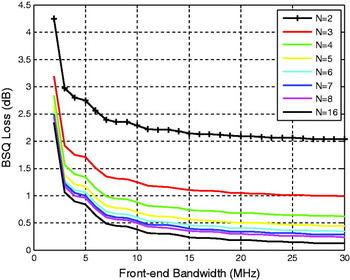
Figure 4 shows the BSQ losses of CP II B1I signal for the different level of quantiser and front-end bandwidth. Here, the satellite's emission bandwidth is assumed to be 30·69 MHz. Along with the increase of front-end bandwidth, the BSQ loss decreases to then reach a near stable level. This characteristic complies with the theory of signal filters. In the mean time, the BSQ loss decreases along with the corresponding increase in the level of quantiser N. When the receiver's front-end bandwidth is 24 MHz and N>4, the BSQ loss is less than 0·5 dB.
BSQ losses of CP II B1I for different quantiser and front-end bandwidth.

When the loss of signal power due to the BSQ of the GNSS receiver is taken into account, the (C/N 0)eff can be rewritten as:

And the (C/N 0)eff_CT_SSC can be rewritten as:

4. SIMULATION
In this section, the radio frequency compatibility between CP II signals on the L1 band and other GNSSs, such as GPS, Galileo, WAAS and EGNOS, will be assessed. The latest parameters of each GNSS are applied in the compatibility calculation.
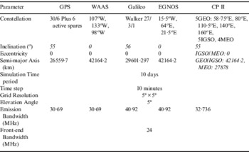
Compass will consist of four MEO satellites, five GEO satellites and five IGSO satellites when the full CP II constellation is deployed. For GPS, a 30 satellite constellation is applied in the interference simulation. The Galileo constellation will consist of 30 satellites in three orbit planes, with 27 operational spacecraft and three in-orbit spares (1/plane). Here we take 27 satellites for the Galileo constellation. WAAS and EGNOS both consist of three GEO satellites. Because the Galileo and Compass systems are both under construction, ideal constellation parameters are assumed in the simulation. The simulation parameters are listed in Table 1 (China Satellite Navigation Office, 2010, Galileo Open Service, 2010, IS-GPS-200, 2010, Zhao, Reference Zhao2006).
Simulation parameters.

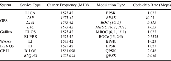
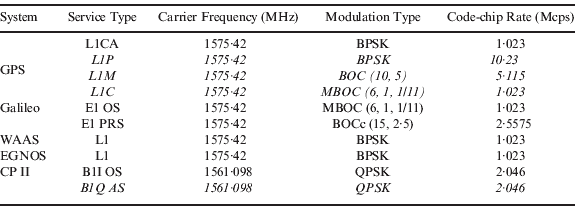
Table 2 summarizes the characteristics of GPS, Galileo, CP II, WAAS and EGNOS signals on the L1 band. The detailed information about the signal parameters can be found in references (China Satellite Navigation Office, 2010, Galileo Open Service, 2010, IS-GPS-200, 2010).
GPS, Galileo, CP II, WAAS and EGNOS signals on the L1 band.
4.1. Simulation results of SSC and CT_SSC
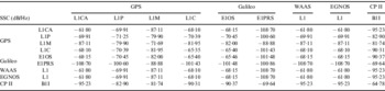
Table 3 lists the SSC simulation results of CP II, GPS, Galileo, WAAS, EGNOS signals on the L1 band with the receiver's front-end bandwidth assumed to be 24 MHz. Because CP II B1I signal and B1Q signal have the same signal structure, the following paragraphs only discuss CP II B1I signal.
SSC on the L1 band.

The simulation results of the SSC show that the SSC performance of the Galileo E1PRS signal outperforms the rest. This is because it uses the BOCc (15, 2·5) sub-carrier modulation which will concentrate the signal power on higher frequency bands where fewer GNSS signals are overlapped. The performance of the CP II B1I signal is next to the Galileo E1PRS signal which is attributed to its carrier frequency (1561·098 MHz) being different from all other GNSS signals (1575·42 MHz). Table 3 also shows that GPS L1CA, WAAS L1 and EGNOS L1 signals have the same SSC results, simply because they have the same carrier frequency, sub-carrier modulation type and code-chip rate.
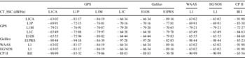
Similar to Table 3, Table 4 lists the CT_SSC simulation results of CP II, GPS, Galileo, WAAS, EGNOS signals on L1 band with the receiver's front-end bandwidth assumed to be 24 MHz. The results show that the CT_SSC performance of the Galileo E1PRS signal is not as good as its SSC. This is also due to the fact that it uses the BOCc (15, 2·5) sub-carrier modulation which concentrates signal power on the higher frequency band. The term sin2(πfΔ) in the CT_SSC expression (12) makes CT_SSC more sensitive for higher frequency signals and results in the poor performance of the Galileo E1PRS signal. Table 4 also indicates that the CP II B1I signal has the best CT_SSC performance for the same reason, that it uses a carrier frequency of 1561·098 MHz which is different from other GNSSs.
CT_SSC on the L1 band.

4.2. Degradation of effective carrier-power-to-noise density ratio
In order to reflect the relative influence of the signal being interfered with, the degradation of (C/N 0)eff, denoted as Δ(C/N 0)eff, is calculated here. Its expression is given as shown below:
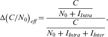
where I Intra is the aggregate equivalent noise power density of the intra-system interference, and I Inter is the aggregate equivalent noise power density of the inter-system interference.
The parameter C i,j, the received power of the j-th interfering signal from the i-th satellite, can be expressed as:
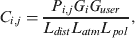
where P i,j is the emission power of the j-th signal from the i-th satellite, L dist is the free-space loss due to the distance between the i-th satellite and receiver, L atm is the loss of the signal due to atmospheric loss, L pol is the polarisation mismatch loss, G i is the antenna gain of the i-th satellite and G user is the antenna gain of receiver.
N 0 is assumed to be −204 dBW/Hz, the atmospheric loss L atm is estimated to be 0·5 dB for all signals and systems, the polarisation mismatch loss L pol is assumed to be 4·0 dB, 1·0 dB, 4·0 dB, 1·0 dB and 1·5 dB for GPS, Galileo, WAAS, EGNOS and CP II respectively, the emission power, received power and other corresponding parameters are obtained from references (China Satellite Navigation Office, 2010, Galileo Open Service, 2010, IS-GPS-200, 2010, Zhao, Reference Zhao2006).
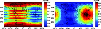
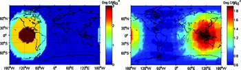
Taking the CP II B1I signal as an example, the Δ(C/N 0)eff between CP II B1I and the signals of GPS, Galileo, WAAS and EGNOS on L1 band are shown as below. In these simulations, the effect of the Doppler offset and BSQ loss of GNSS receivers are considered. All interference simulation results are calculated with the worst case scenario that is minimum emission power for desired signal, maximum emission power for all interfering signals, and the worst situation of Doppler offset for all signals. In following figures, Δ(C/N 0)eff is denoted as Deg. C/N0 and its engineering unit is dB.
Scenario 1:
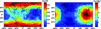
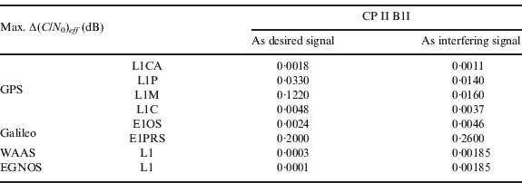
The maximum Δ(C/N 0)eff between the GPS L1CA and CP II B1I signals are depicted in Figure 5. The maximum inter-system interference on GPS L1CA caused by the CP II B1I signal is never above 0·0011 dB. On the other hand, the maximum inter-system interference on CP II B1I signal caused by the GPS L1CA is up to 0·0018 dB. This indicates that GPS L1CA causes more interference on CP II B1I than CP II B1I causes on GPS L1CA.
Maximum Δ(C/N0)eff between GPS L1CA signal and CP II B1I signal. (Left) Maximum Δ(C/N0)eff of CP II B1I due to GPS L1CA inter-system interference. (Right) Maximum Δ(C/N0)eff of GPS L1CA due to CP II B1I inter-system interference.

Scenario 2:
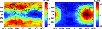
Figure 6 shows the maximum Δ(C/N 0)eff between the GPS L1P and CP II B1I signals. This indicates that GPS L1P causes more interference on CP II B1I than CP II B1I causes on GPS L1P.
Maximum Δ(C/N0)eff between GPS L1P signal and CP II B1I signal. (Left) Maximum Δ(C/N0)eff of CP II B1I due to GPS L1P inter-system interference. (Right) Maximum Δ(C/N0)eff of GPS L1P due to CP II B1I inter-system interference.

Scenario 3:
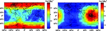
The maximum Δ(C/N 0)eff between the GPS L1M and CP II B1I signals is depicted in Figure 7. This indicates that GPS L1M causes more interference on CP II B1I than CP II B1I causes on GPS L1M
Maximum Δ(C/N0)eff between GPS L1M signal and CP II B1I signal. (Left) Maximum Δ(C/N0)eff of CP II B1I due to GPS L1M inter-system interference. (Right) Maximum Δ(C/N0)eff of GPS L1M due to CP II B1I inter-system interference.

.
Scenario 4:
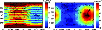
The maximum Δ(C/N 0)eff between the GPS L1C and CP II B1I signals is depicted in Figure 8. This indicates that GPS L1C causes more interference on CP II B1I than CP II B1I causes on GPS L1C.
Maximum Δ(C/N0)eff between GPS L1C signal and CP II B1I signal. (Left) Maximum Δ(C/N0)eff of CP II B1I due to GPS L1C inter-system interference. (Right) Maximum Δ(C/N0)eff of GPS L1C due to CP II B1I inter-system interference.

Scenario 5:
The maximum Δ(C/N 0)eff between the Galileo E1OS and CP II B1I signals is depicted in Figure 9. The maximum inter-system interference on CP II B1I caused by the Galileo E1OS signal is never above 0·0024 dB. On the other hand, the maximum inter-system interference on the Galileo E1OS signal caused by CP II B1I is up to 0·0046 dB. This indicates that Galileo E1OS causes less interference on CP II B1I than CP II B1I causes on Galileo E1OS.
Maximum Δ(C/N0)eff between Galileo E1OS signal and CP II B1I signal. (Left) Maximum Δ(C/N0)eff of CP II B1I due to Galileo E1OS inter-system interference. (Right) Maximum Δ(C/N0)eff of Galileo E1OS due to CP II B1I inter-system interference.

Scenario 6:
The maximum Δ(C/N 0)eff between the Galileo E1PRS and CP II B1I signals is depicted in Figure 10. This indicates that Galileo E1PRS causes less interference on CP II B1I than CP II B1I causes on Galileo E1PRS.
Maximum Δ(C/N0)eff between Galileo E1PRS signal and CP II B1I signal. (Left) Maximum Δ(C/N0)eff of CP II B1I due to Galileo E1PRS inter-system interference. (Right) Maximum Δ(C/N0)eff of Galileo E1PRS due to CP II B1I inter-system interference.

Scenario 7:
The maximum Δ(C/N 0)eff between the WAAS L1 and CP II B1I signals is depicted in Figure 11. The results show that WAAS L1 causes very limited interference on CP II B1I.
Maximum Δ(C/N0)eff between WAAS L1 signal and CP II B1I signal. (Left) Maximum Δ(C/N0)eff of CP II B1I due to WAAS L1 inter-system interference. (Right) Maximum Δ(C/N0)eff of WAAS L1 due to CP II B1I inter-system interference.

Scenario 8:
The maximum Δ(C/N 0)eff between the EGNOS L1 and CP II B1I signals is depicted in Figure 12. The results show that EGNOS L1 also causes very limited interference on CP II B1I.
Maximum Δ(C/N0)eff between EGNOS L1 signal and CP II B1I signal (Left) Maximum Δ(C/N0)eff of CP II B1I due to EGNOS L1 inter-system interference (Right) Maximum Δ(C/N0)eff of EGNOS L1 due to CP II B1I inter-system interference.

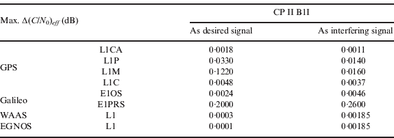
Table 5 summarises the simulation results, and lists the maximum Δ(C/N 0)eff of CP II B1I. From the simulation results listed above, it can be concluded that both WAAS and EGNOS cause very limited interference on CP II because they are the augmentation systems which are deployed on specific areas. GPS causes more interference on CP II than CP II causes on GPS. Finally CP II causes more interference on Galileo than Galileo causes on CP II.
Maximum Δ(C/N0)eff of CPII BII.
5. CONCLUSIONS
The radio frequency compatibility with existing signals and services must be assessed carefully before any new signal or service of GNSS is deployed. This paper analyses the effect of Doppler offset, code tracking loop of receiver and BSQ loss on compatibility computation, then presents a modified assessment methodology covering these factors, which are ignored in traditional methodologies, for better GNSS compatibility assessment.
As a developing system, the CP II system is especially focused on its performance and the interference it causes on other GNSSs. However, neither have the system parameters of CP II have been officially released, nor has a comprehensive compatibility assessment of CP II been done. This paper therefore assesses the compatibility of CP II comprehensively taking into account the latest available system parameters and presents the results of SSC, CT_SSC and Δ(C/N 0)eff, which take into account the effect of Doppler offset, code tracking loop and BSQ loss. The simulation covers GPS, Galileo, WAAS, EGNOS and CP II signals on L1 band. The results show that the Galileo E1PRS signal has the best SSC performance, and that the CP II B1I signal also has excellent performance of SSC. Out of all these signals, the CP II B1I signal has the best CT_SSC performance. Furthermore, the calculation results of Δ(C/N 0)eff which is the most important factor to assess the inter-system interference are given. The maximum interference caused by Compass to other GNSSs is mainly due to geostationary satellites in the Asia and Pacific region. ITU rules that the interference is insignificant when it is below 0·25 dB (Hein, 2001), therefore CP II B1I should not cause compatibility problems when it is fully deployed.
Note that the study on the compatibility assessment in this paper is focused on Δ(C/N 0)eff based on SSC. The compatibility assessment based on Δ(C/N 0)eff_CT_SSC and extra interference caused by non-GNSS interfering source will be considered for further work. Meanwhile, the proper threshold values for SSC, CT_SSC and Δ(C/N 0)eff is also worth further studying.
ACKNOWLEDGEMENTS
This work has been sponsored by the National High Technology under the following contracts: 2009AA12Z322 and by Science Foundation of the Chinese Academy of Space Technology.