I. INTRODUCTION
As an emerging and sustainable fabrication technology, laser additive manufacturing allows rapid introduction of new designs, shortening of the product implementation cycle, and manufacturing and/or repairing to the near-net shape of the aerospace components, such as aeroengine subassemblies fabricated from nickel-based superalloys. Reference Qi, Azer and Ritter1–Reference Dupont, Lippold and Kiser3 During laser additive manufacturing, both powder and wire have been used as feedstock, but the latter has lower cost, higher material efficiency (reduced waste), lower contaminant pick-up (higher quality), lower oxidation (fewer defects), and higher deposition rate (productivity). Reference Andersson and Sjoberg4–Reference Ion7
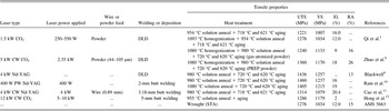
To date, the microstructure and mechanical properties of laser additive manufactured IN718 using conventional CO2 and Nd:YAG lasers have been extensively studied. Reference Qi, Azer and Ritter1,Reference Ng, Bi and Zheng2,Reference Baufeld5,Reference Zhao, Chen, Lin and Huang8–Reference Hong, Park, Park, Eom, Kim and Kang12 The typical tensile properties obtained for the IN718 alloy are summarized in Table I, including the results for the conduction-mode condition generally used for direct laser deposition, as well as the mechanical performance obtained for keyhole-mode laser welding of butt joints. Zhao et al. Reference Zhao, Chen, Lin and Huang8 evaluated the mechanical properties of laser deposited IN718 using gas-atomized and plasma rotating electrode processed (PREP) powders. The tensile properties of the deposit using PREP powders were superior to the wrought IN718 alloy, while the performance of the gas-atomized powder deposit was inferior, which was attributed to the presence of gas porosity in the feedstock that rendered porosity and microcracks in the microstructure. In contrast, Blackwell Reference Blackwell9 reported that tensile failure in laser deposited IN718 was caused by the lack of fusion/bonding between the successive layers of the deposit.
Room temperature tensile properties of laser additive manufactured and welded IN718.

Note: STA is the solution treated and aged condition; PW denotes pulse wave; CW denotes continuous wave.
Besides the influence of the defects on the tensile properties, the unique microstructural characteristics of the laser deposited IN718, such as the significantly refined substructure, also contribute notably to the mechanical performance. For instance, as compared to the tensile properties of as-cast and wrought alloys, CO2 laser deposited IN718 obtained using a PREP powder feed exhibited equivalent or even superior mechanical performance due to the small secondary dendrite arm spacing and refined grain structure resulting from the rapid solidification rate. Reference Qi, Azer and Ritter1 For Nd:YAG laser butt welding of IN718, Cao et al. Reference Cao, Rivaux, Jahazi, Cuddy and Birur11 obtained similar results; the welds exhibited equivalent or superior tensile properties, namely yield strength (YS), ultimate tensile strength (UTS), and elongation (El.), as compared to the aerospace specification AMS 5663 for wrought IN718.
The prevailing influences of the intermetallic and carbide phases on the tensile properties have been well documented for IN718. The two main strengthening phases, γ′ and γ″, are coherent with the matrix and thus can improve the tensile strength. However, other intermetallic phases such as Laves and Ni3Nb-δ particles, and secondary Nb/Ti-rich carbides, are all incoherent with the matrix and have different influences on the tensile properties. The Nb/Ti-rich MC type carbides are reported to reduce the ductility Reference Dupont, Lippold and Kiser3,Reference Yang, Xu, Jiang and Liang13 and have a limited strengthening effect either directly (e.g., through dispersion hardening) or, more commonly, indirectly (e.g., by retarding grain boundary sliding and permitting stress relaxation along the grain boundaries). Reference Donachie and Donachie14 These carbides are typically present in the interdendritic regions or grain boundaries of the γ-matrix and are able to initiate microvoids. The effect of platelet or needle-like incoherent Ni3Nb-δ phase on the mechanical properties has not been consistently reported in the literature. Reference Qi, Azer and Ritter1,Reference Loria15,Reference Rao, Kumar, Srinivas and Sarma16 In general, the Ni3Nb-δ phase is considered to have poor bonding characteristics with the γ-matrix, leading to the loss of the strength and creep life for IN718. Reference Qi, Azer and Ritter1,Reference Loria15 However, it was also reported that the precipitation of the Ni3Nb-δ phase along the γ grain boundaries can block grain boundary sliding, refine the grain size, strengthen the grain boundary and thus enhance the tensile strength. Reference Rao, Kumar, Srinivas and Sarma16 It appears that the characteristics (morphology, quantity, and distribution) of the Ni3Nb-δ phase in the γ-matrix may explain the different mechanical performances, as reported in the literature; for instance, when the Ni3Nb-δ phase is present in large quantities there is no strengthening effect, but a small quantity can refine the grain size and improve the tensile properties, fatigue resistance, and creep rupture ductility. Reference Donachie and Donachie14 The Laves [(Ni, Cr, Fe)2(Nb, Mo, Ti)] particles that precipitate in the interdendritic regions or grain boundaries during laser welding or deposition are also reported to exhibit poor bonding with the γ-matrix, and, in turn, deteriorate the mechanical properties, especially the tensile ductility, fracture toughness, fatigue and creep rupture properties. Reference Qi, Azer and Ritter1,Reference Dupont, Lippold and Kiser3,Reference Ram, Reddy, Rao, Reddy and Sundar10,Reference Biswas, Reddy, Mohandas and Murthy17 Particularly, the formation of the Laves phase (i) depletes the γ-matrix of the principal alloying elements required for solid solution strengthening; (ii) results in a weakened structure, especially at the interface between the Laves phase and the γ-matrix; (iii) promotes excessive microvoid nucleation; and (iv) presents preferential sites for easy crack initiation and propagation along its low energy fracture paths. Reference Qi, Azer and Ritter1,Reference Dupont, Lippold and Kiser3,Reference Ram, Reddy, Rao, Reddy and Sundar10,Reference Cao, Rivaux, Jahazi, Cuddy and Birur11 Moreover, the formation of both Laves and Ni3Nb-δ phases consumes the available Nb so that it is not available for the precipitation of the coherent strengthening phases, γ″ and γ′. To this end, considerable dissolution of the Laves phase can improve the tensile ductility, which has been well confirmed through post-weld heat treatment by Ram et al. Reference Ram, Reddy, Rao, Reddy and Sundar10
Notwithstanding this current understanding of the phase constituents and mechanical performance of the laser deposited IN718, information on additive manufacturing or repair of IN718 using wire feeding and a high power continuous wave (CW) fiber laser is limited. From an industrialization perspective, fiber lasers have remarkable advantages including high energy efficiency, good beam quality, flexible fiber beam delivery, small footprint, good process versatility, automation capacity, and low overall costs. Reference Chen, Pinkerton and Li18 In this work, laser deposition with wire feed was performed on service exposed PM substrates. The objective was to substantiate the process for additive manufacture or repair of IN718 components. Microstructural characterization and mechanical property evaluation of the DLD and DLD-PM IN718 were conducted in the current work and compared with the service-exposed IN718. To understand the tensile failure mechanisms, the fracture surfaces of the PM, DLD, and DLD-PM samples were systematically analyzed using SEM.
II. EXPERIMENTAL
Coupons of the PM substrates were extracted directly from a retired, service-exposed IN718 aerospace component that had nominal and measured chemical compositions as indicated in Table II. Although the details of the manufacturing process for the IN718 aerospace component were not disclosed, it may be reasonably assumed that the alloy was processed through casting and forging followed by a standard solutionizing and aging heat treatment prior to the “normal” long-time service. Hereafter, the term PM refers to the “service-exposed” condition unless otherwise noted, as, for instance, when it was fully heat treated again after laser deposition.
Nominal and measured chemical compositions of IN718 PM, filler wire, and laser deposits (wt%).

a Individual values represent the upper limit for the nominal composition.
b Measured values using an Olympus Delta X-ray Fluorescence (XRF) analyzer at a beam voltage of 40 V and current 35 A.
In this study, laser deposition was conducted on the IN718 PM substrate using a 5 kW CW solid-state Yb-fiber laser system (YLR-5000, IPG Photonics, Oxford, MA) equipped with an ABB robot. A collimation lens of 150 mm, a focal lens of 250 mm, and a fiber diameter of 600 µm were used to produce a nominal focusing spot diameter of approximately 1.0 mm. A positive defocusing distance of +12 mm was used to obtain a laser power density of approximately 792 W/mm2. The laser head was inclined 2–3° both along the lateral side and from the vertical position toward the scanning direction to avoid any damage to the equipment from the laser beam reflection. The fiber laser beam, with a wave length of about 1.07 µm, was positioned on the top surface of the deposit. To protect the molten metal during deposition, the laser deposited material was shielded using two streams of Ar gas flow. One stream of Ar at a flow rate of 30 cfh (2.36 × 10⁻⁴ m3/s) was directed toward the scanning direction at an angle of 18–20° to the deposit surface, while the other was directed opposite to the scanning direction at a flow rate of 20 cfh (1.57 × 10⁻⁴ m3/s). The IN718 filler wire, supplied by Haynes International Inc., was ∼0.89 mm in diameter and had a nominal composition as given in Table II. The IN718 filler wire was axially fed from the laser scanning direction at an inclination angle of 30° from the top surface of the deposit where interception with the incident laser beam occurred. A schematic of the experimental setup has been reported in an earlier publication. Reference Zhang, Cao, Wanjara and Medraj19 It is noteworthy that each layer was deposited along a single scanning direction on the IN718 PM substrates to produce two types of coupons for the final mechanical property evaluation: (1) DLD IN718 (i.e., 100% direct laser deposited) and (2) DLD-PM (i.e., 50% DLD IN718 and 50% IN718 PM).
After laser deposition, the DLD and DLD-PM coupons were solution treated and aged (STA). The solution heat treatment was carried out in vacuum at a temperature of 954 °C (1750 ± 25 °F) for one hour and then cooled (with inert Ar gas) at a minimum rate of 16.7 °C/min (30 °F/min) to a temperature of 538 °C (1000 °F) followed by rapid cooling in Ar. The aging consisted of the following steps: heating to 732 °C (1350 ± 25 °F), soaking for 8 h, furnace cooling under Ar to 599 °C (1110 ± 25 °F) and holding for 8 h, and finally Ar quenching.
The metallographic samples were characterized in both the as-deposited and post-deposition heat treated (PDHT) conditions. Each laser deposited coupon was sectioned transverse to the scanning direction using a precision cut-off saw to extract specimens for metallographic examination. After sectioning, the specimens were mounted, ground, and polished to a surface finish of 0.04 µm, followed by electrolytic etching in a saturated solution of 10 g oxalic acid in 100 mL distilled water using a voltage of 6 V for 8 s. Optical microscopy (OM) on a GX-71 system (Olympus Corporation, Tokyo, Japan) was used for examining the macrostructural features in the deposited material zone (DMZ).
The microhardness was measured using a load of 300 g and a dwell period of 15 s on a Vickers microhardness (HV) machine (Struers Duramin A300, Struers DuraScan, Salzburg, Austria), equipped with a fully automated testing cycle (stage, load, focus, measure). At an indent interval of 0.2 mm, at least three hardness lines were measured to determine the average hardness profile across each deposit. Standard tensile samples with a gage length of 16.26 mm (0.640″ ± 0.005″) and a diameter of 4.06 mm (0.160″ ± 0.003″) were machined in accordance with ASTM-E8-04 from the IN718 PM, DLD, and DLD-PM coupons. Room temperature tensile testing was conducted at a strain rate of 8.3 × 10⁻⁵ s−1 before the yield point and 8.3 × 10⁻⁴ s−1 after yielding using a United SFM-30 system. The microstructural constituents in the DMZ and on the fracture surface of the IN718 PM, DLD, and DLD-PM specimens were observed using SEM (Hitachi S-3400N, Tokyo, Japan) with secondary electron imaging (SEI) and backscattered electron imaging (BSEI). Energy dispersive x-ray spectroscopy (EDXS) was used to identify the chemical composition of the different secondary and intermetallic phases. To further improve the reliability of the phase identification on the fracture surfaces, the secondary and intermetallic phases were carefully focused and their compositions were measured at a distance of approximately 10 mm from the EDXS detector. Then these secondary and intermetallic particles were further confirmed by comparing and contrasting with the same phases obtained from metallography and literature.
III. RESULTS AND DISCUSSION
A. Microstructure
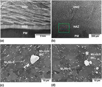
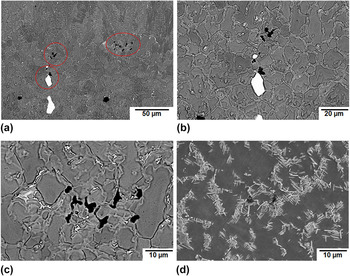
As shown in Fig. 1(a) (OM) and Fig. 1(b) (SEM), a multibead and multilayer deposit with no visible macroporosity and macrocracks could be produced under optimized process conditions using a high power fiber laser with wire feed addition. Three distinct regions are identifiable in the images shown in Figs. 1(a) and 1(b): (1) the IN718 PM, (2) the heat-affected zone (HAZ) that includes the partially melted zone (PMZ), and (3) the DMZ.
A multibead and multilayer deposit in the (a) as-deposited condition, OM image and (b) the heat treated condition, SEM image. BSEI of the PM in the (c) service-exposed condition and the (d) reheat treated condition after laser deposition.

1. Parent metal
The microstructures of the IN718 PM in the service-exposed (i.e., as-received) and heat treated conditions are shown in Figs. 1(c) and 1(d), respectively. The PM in both conditions consisted primarily of the equiaxed austenitic γ grains, MC carbide particles, and platelet Ni3Nb-δ precipitates as well as the age-hardening/strengthening phases γ″ and γ′. The γ grains comprise the face-centered-cubic (fcc) Ni-based continuous matrix phase with solid solution elements (e.g., Co, Cr, Mo, and W). Randomly distributed Nb-rich MC type primary carbides with sizes up to 10 µm were observed at the γ-matrix grain boundaries. Platelet Ni3Nb-δ precipitates, approximately 1–5 µm in length, were distributed within the γ grains and at the grain boundaries. Their presence and morphology are mainly attributed to the multiple thermal cycles during service of the IN718 aerospace component (from which the PM substrates were extracted). Reference Dupont, Lippold and Kiser3,Reference Zhang, Cao and Wanjara20,Reference Hooijmans, Lippold, Lin and Loria21 An average γ grain size of 14 μm was determined for the service-exposed condition [Fig. 1(c)]. In the fully heat treated condition (after laser deposition), slight coarsening of the γ grains (approximately 17 μm) was observed, as shown in Fig. 1(d).
2. HAZ between PM and DMZ
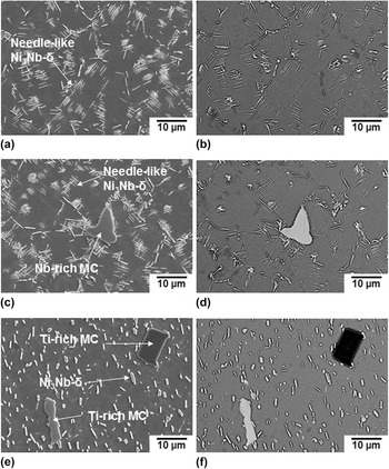
Figure 2 shows the details of the HAZ [located within the inset in Fig. 1(b)] of the multibead and multilayer deposit in the heat treated condition. Compared to the PM, more complex microstructures were observed in the HAZ between the PM and the DMZ. In particular, within the HAZ close to the DMZ, referred to as the near-HAZ, a large amount of the needle-like Ni3Nb-δ precipitates were apparent, but no evidence of the Nb- and/or Ti-rich MC type carbides could be ascertained, as shown in Figs. 2(a) and 2(b). The precipitation of these needle-like Ni3Nb-δ precipitates in the near-HAZ occurs during post-deposition solution heat treatment from the liquid “particle” structure that forms due to the dissolution of the Ni3Nb-δ or γ″ in the matrix during the heating stage of laser deposition. Reference Zhang, Cao and Wanjara20,Reference Hooijmans, Lippold, Lin and Loria21 Clearly, the temperature in the DMZ is higher than the melting temperature of the IN718 alloy (1350 °C); thus the near-HAZ (i.e., the HAZ close to the DMZ) may experience temperatures surpassing the γ/MC type carbide eutectic temperature (1250 °C). As such, the MC carbides can completely dissolve into the γ-matrix, which reasonably accounts for the absence of the carbides in the near-HAZ [Figs. 2(a) and 2(b)].
Microstructures of the multibead and multilayer deposit in the heat treated condition, located within the inset shown in Fig. 1(b): (a–b) near-HAZ, (c–d) mid-HAZ, and (e–f) far-HAZ.

Similarly, a large amount of the needle-like Ni3Nb-δ precipitates were observed in the mid-HAZ [Figs. 2(c) and 2(d)]. However, MC type carbides were also present in this region though some partial dissolution was evident. Hence, as compared to the near-HAZ, the temperatures in the mid-HAZ are lower but most likely close to or below the γ/MC type carbide eutectic temperature.
In the far-HAZ (i.e., the HAZ close to the PM), the MC type carbides appeared intact without any evidence of dissolution [Figs. 2(e) and 2(f)]. Also, considering that the solution heat treatment was carried out at 954 °C, which is lower than the solvus temperature (995 °C) of the Ni3Nb-δ precipitates, neither the carbides nor the Ni3Nb-δ precipitates in the HAZ and PM were dissolved in the PDHT condition. Although the far-HAZ after the heat treatment appears to have a microstructure similar to that of the PM (i.e., consisting of the γ-matrix, platelet Ni3Nb-δ, Nb-rich and/or Ti-rich MC primary carbides), the strengthening phase γ″ can transform to Ni3Nb-δ when the temperature is above 861 °C. Reference Dupont, Lippold and Kiser3
3. Deposited material zone
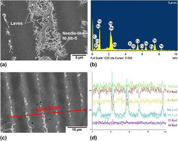
The DMZ, which had a chemical composition similar to the IN718 PM (Table II), exhibited typical dendritic structures, as shown in Fig. 3(a). Solidification of IN718 starts with the precipitation of primary γ, which causes the enrichment of Nb, Mo, Ti, and C in the interdendritic liquid. The subsequent liquid transforms to γ and NbC through a eutectic reaction that consumes most of the carbon available in the material until another eutectic type reaction, liquid → (γ + Laves phases), occurs and terminates the solidification process. Reference Dupont, Lippold and Kiser3,Reference Zhao, Chen, Lin and Huang8,Reference Ram, Reddy, Rao and Reddy22–Reference Xu, Lv, Liu, Shu, He and Xu24 From EDXS, spot analyses on the Laves particles demarcated in Fig. 3(a) revealed that they consist of Ni, Cr, Fe, Nb, Mo, and Ti, as shown in the typical spectrum given in Fig. 3(b). With due consideration of the smaller size and fraction of the Ni3Nb-δ particles within the interdendritic regions, an EDXS line scan across the dendrites in the DMZ [Figs. 3(c) and 3(d)] can further attest to the Laves phase being rich in Nb, Ti, and Mo, but lean in Fe, Cr, and Ni, as compared to the γ-matrix. In the PDHT condition, the solution annealing temperature of 954 °C used resulted in partial dissolution of the Laves particles (the eutectic temperature of (γ + Laves) is 1200 °C) and led to Nb accumulation in the interdendritic regions. Sufficient concentration of Nb around the Laves particles can then initiate the formation of the needle-like δ phase [Fig. 3(a)], an equilibrium orthorhombic incoherent Ni3Nb precipitate that has a precipitation temperature range of 860–995 °C. Reference Ram, Reddy, Rao and Reddy22
(a) Microstructure consisting of Laves phase and needle-like Ni3Nb-δ precipitates in the heat treated condition, (b) typical EDXS point spectrum from a spot analysis on the Laves phase, and (c, d) EDXS line scan across the dendritic structure in the DMZ.

B. Defects
HAZ liquation cracks were observed in the PMZ close to the DMZ in the as-deposited condition [Figs. 4(a)–4(d)]. In the PDHT condition, the extent of HAZ microfissuring was markedly reduced, as shown in Fig. 4(d), and can be attributed to healing. HAZ liquation cracking can occur in the wrought IN718 substrate due to (i) the constitutional liquation of Nb/Ti-rich MC carbides and (ii) the segregation of B, S, and P in the HAZ grain boundaries. Reference Dupont, Lippold and Kiser3 The low equilibrium distribution coefficients of solute and/or impurity elements B (0.04 in Ni), S (nearly 0 in Ni), and P (0.02 in Ni) lead to their segregation into the grain boundaries, cause a local depression of the melting temperature and thus promote the formation of liquation films along the grain boundaries. Reference Dupont, Lippold and Kiser3,Reference Zhang, Cao and Wanjara20 In spite of the presence of the HAZ liquation cracking in the DLD-PM coupons, tensile fracture occurred exclusively in the DLD region, which suggests that the HAZ liquation cracks are not the dominating factor for the failure of the DLD-PM tensile samples.
Liquation cracking in the PMZ of the HAZ in the (a–c) as-deposited and (d) PDHT conditions.

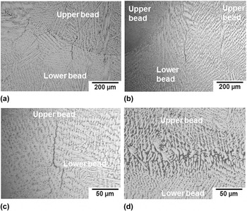
In the DMZ, weld metal liquation cracking was frequently observed in the lower beads near the interfacial layer in the as-deposited condition, as shown in Fig. 5. This region of the lower beads acts as the HAZ of the adjacent upper layer beads that are deposited subsequently. Therefore, these microcracks are quite similar to the HAZ microfissures or liquation cracks, as widely encountered in IN718 welds, Reference Dupont, Lippold and Kiser3 and are usually termed as weld metal liquation cracking in multipass welding. Reference Dupont, Lippold and Kiser3 The DMZ has a rapidly solidified cast microstructure after laser deposition and thus liquation cracking is promoted by the melting of the Laves phase rather than constitutional liquation of the Nb/Ti-rich carbides, given that the former precipitates at a lower temperature and the latter has a much lower fraction. As shown in Figs. 5(a)–5(c), the weld metal liquation cracks can propagate from the lower beads near the interfacial area along the grain boundaries and even extend into the upper newly deposited layer. In the PDHT condition, the absence of weld metal liquation cracks in the interfacial area, as shown in Fig. 5(d), can be attributed to healing that occurs due to (i) the lower amount of Laves phase available due to its partial dissolution during the heating stage of the solution heat treatment, (ii) the improved strength of the DMZ due to the release of Nb into the γ-matrix caused by the partial dissolution of the Laves phase at the heating stage and the precipitation of the γ′ and γ″ strengthening phases at the aging stage, and (iii) the release of thermal strains and shrinkage stresses (that are a result of rapid solidification after laser deposition) during the solution heat treatment. Reference Dupont, Lippold and Kiser3,Reference Zhang, Cao and Wanjara20 The healing of the weld metal liquation cracks in the DMZ during the heat treatment after laser deposition is deliberated to diminish the deterioration in the mechanical performance.
Weld metal liquation cracks in the (a–c) as-deposited condition and healing with the (d) PDHT condition.

C. Mechanical properties
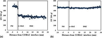
The average Vickers microindentation hardness profiles across the deposits (from DMZ to PM) in the as-deposited and PDHT conditions are shown in Fig. 6. The hardness of the DMZ in the PDHT condition (457 ± 15 HV) is much higher than that in the as-deposited condition (275 ± 30 HV). In the PDHT condition, the DMZ has a hardness that is similar to but slightly lower than the fully heat treated PM (463 ± 16 HV), indicating that the hardness can be essentially recovered to that of the PM. The slightly lower hardness is due to the presence of undissolved Nb-rich Laves particles and the formation of the needle-like Ni3Nb-δ phase particles in the DMZ that lowers the amount of Nb available for reprecipitation of strengthening phases γ′ and γ″ during the heat treatment after laser deposition.
Average hardness profiles in the (a) as-deposited and (b) PDHT conditions, which indicate that the hardness in the DMZ is nearly recovered to the value of the PM in the fully heat treated condition.

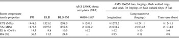
Although the overall tensile properties of the DLD and DLD-PM coupons are lower than the PM, both the UTS and YS are well above the minimum values as defined in the specifications AMS 5596K and AMS 5663M. However, the ductility values of the DLD and DLD-PM coupons are slightly lower than the specifications. Both DLD and DLD-PM coupons have similar UTS, YS, and elongation, but the DLD-PM coupon has twice the ductility (RA) of the DLD IN718. All the DLD-PM coupons fractured in the DLD portion of the tensile specimen, indicating that the DMZ is weaker than the service-exposed PM.
D. Fractography
To better understand the tensile failure mechanisms, the fracture surfaces of the IN718 PM, DLD, and DLD-PM coupons were examined using SEM and EDXS. It is noteworthy that all the DLD-PM coupons failed in the DLD section of the tensile specimens and thus similar fracture surface results were obtained for both the DLD and DLD-PM coupons. As shown in Figs. 7(a) and 7(b), the tensile fracture surfaces of the PM that are indicative of transgranular ductile failure exhibited fine, deep, and uniform equiaxed dimples, within which platelet Ni3Nb-δ particles were frequently present. Some MC carbides can also be observed on the fracture surface, as shown in Fig. 7(a). In contrast, the tensile fracture surfaces of both the DLD and DLD-PM coupons revealed irregular and shallow dimple structures and preferential failure along the interdendritic regions or grain boundaries, where evidence of Laves and needle-like Ni3Nb-δ particles was observed, as shown in Figs. 7(c) and 7(d).
Typical tensile fracture surfaces of the (a, b) PM and (c, d) laser deposited IN718 (taken from a DLD-PM coupon).

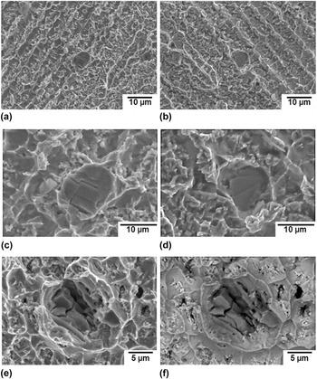
Both Nb-rich and Ti-rich MC carbides were observed on the tensile fracture surfaces of the PM, DLD, and DLD-PM coupons, as shown in Figs. 8 and 9, respectively. Compared with the size of the MC carbides in the PM (approximately 15 µm as shown in Fig. 8), the size of those in the DLD and DLD-PM coupons was finer (approximately 8 µm as shown in Fig. 9), probably due to the rapid cooling conditions during laser deposition that may suppress the γ/NbC eutectic reaction. As illustrated in Figs. 8(a) and 8(b), the Nb-rich MC carbides appeared darker in SEI mode than under BSEI, which indicates the presence of heavier elements, as compared to the γ-matrix. The composition of the MC carbide was confirmed by EDXS to consist mainly of Nb and C. In addition, Ti-rich MC carbides were observed on the fracture surfaces of the PM, DLD, and DLD-PM tensile samples, as shown in Figs. 8(c), 8(d), and 9. In particular, these carbides appeared to be dark in both SEI and BSEI modes, which indicates the presence of lighter elements, as compared to the γ-matrix. Through EDXS, the composition of this MC carbide [Figs. 8(c) and 8(d)] was ascertained to mainly consist of Ti and C. The presence of Nb-rich and Ti-rich MC carbides on the tensile fracture surfaces of the PM, DLD-PM, and DLD coupons can be related to the segregation of the elements C, Nb, and Ti. In particular, both Nb and Ti have low values of equilibrium distribution coefficient, k, in IN718, i.e., 0.48 for Nb and 0.69 for Ti, as well as negligible solid state diffusion coefficients. Reference Dupont, Lippold and Kiser3 Therefore, both Nb and Ti will tend to segregate to form Nb-rich or Ti-rich compounds through eutectic reactions, which usually locate at the interdendritic regions or grain boundaries during solidification.
Tensile fracture surface characteristics of PM showing (a, b) a cracked Nb-rich MC carbide, (c, d) a fractured Ti-rich MC carbide exhibiting cleavage features, and (e, f) evidence of cracks having formed at the brittle MC carbide particles with propagation along grain boundaries (a, c, e are with SEI whereas b, d, f are with BSEI).

Tensile fracture surface characteristics of DLD IN718 showing (a–d) a Ti-rich MC carbide on the mating surfaces and (e, f) a cracked Ti-rich MC carbide (all are with SEI except for the image (f) that was taken with BSEI).

It is noteworthy that Ti-rich MC carbides were found on the mating fracture surfaces of the DLD tensile specimens, as shown in Figs. 9(a)–9(d); this suggests that besides the possibility of carbide-matrix decohesion/debonding, fracture can also occur within these particles and render cleavage characteristics. Moreover, it is evident that the cracks that form in the MC carbides of the PM [Figs. 8(e) and 8(f)] and DLD [Figs. 9(e) and 9(f)] IN718 may subsequently propagate along the grain boundaries or interdendritic regions, respectively, which seems to be consistent with the conventional view of the brittle Nb-rich and Ti-rich MC carbides as crack initiators that can lead to the premature failure of the materials.
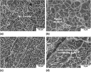
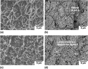
As mentioned above, platelet Ni3Nb-δ particles were frequently apparent at the bottom of the dimples on the tensile fracture surface of the PM; thus, microvoids initiate at the platelet Ni3Nb-δ particle and decohesion may appear at the particle/matrix interfaces [Figs. 10(a) and 10(b)]. In contrast, at the bottom of the dimples on the tensile fracture surfaces of the DLD IN718, the Laves particles were mainly observed with the needle-like Ni3Nb-δ phase located around the partially dissolved Laves phase. In particular, the considerable dissolution of the Laves phase during solution heat treatment leaves a sufficient amount of Nb around the partially dissolved Laves particles, which then become favorable nucleation sites for the formation of the needle-like Ni3Nb-δ phase. Reference Qi, Azer and Ritter1
Tensile fracture surfaces showing (a, b) platelet Ni3Nb-δ in the PM and (c, d) needle-like Ni3Nb-δ in DLD coupon.

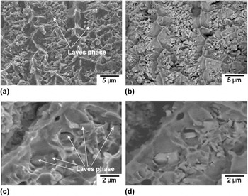
For the DLD and DLD-PM coupons, Figs. 11 and 12 show further evidence of fracture initiating initially through cracking in the Laves particles, or debonding/decohesion and void growth at the Laves particle/matrix interfaces. Specifically, the Laves particles that are propitious nucleation sites for considerable microvoid initiation (Fig. 11) facilitate the fracture process and lead to the growth of macroscopic cracks along the particle/matrix interfaces, as shown in Fig. 12. It is noteworthy that element mapping of the DLD fracture surface [Figs. 12(d) and 12(e)] using a SEM with EDXS demonstrates that (1) the Laves particles are rich in Nb, Mo, and Ti but lean in Fe, Cr, and Ni as compared with the matrix and (2) the cracks initiate and propagate along the Laves particles. On the basis of these fracture surface observations, it can be reasoned that the reduced tensile strength and ductility of the PDHT DLD and DLD-PM coupons, as compared to the IN718 PM (Table III), can be attributed primarily to the presence of Laves phase in the DMZ microstructure, which agrees well with the findings reported previously for IN718 weldments and deposits. Reference Qi, Azer and Ritter1,Reference Dupont, Lippold and Kiser3,Reference Ram, Reddy, Rao, Reddy and Sundar10,Reference Cao, Rivaux, Jahazi, Cuddy and Birur11
The presence of Laves phase on the tensile fracture surfaces of (a, b) DLD and (c, d) DLD-PM coupons.

Tensile fracture surface characteristics of DLD and DLD-PM coupons: (a–c) Laves particles along the cracks, (d, e) EDXS mapping indicating that Laves particles are associated with cracks and are rich in Nb, Mo, Ti but lean in Fe, Cr, and Ni as compared to the γ-matrix.

Room temperature tensile properties of IN718 in the PDHT condition.

According to aerospace specifications AMS 5596K and 5663M, the laser deposited IN718 (DLD and DLD-PM) in the PDHT condition has adequate tensile strength (YS and UTS) but does not strictly meet the minimum requirements of the ductility (Table III). In addition, all the tensile properties (both strength and ductility) of the laser deposited IN718 in the PDHT condition are markedly lower than the IN718 PM. The occurrence of tensile failure exclusively in the DLD portion of the DLD-PM specimens indicates that (i) the bonding between the successive layers of the laser deposited materials is also weaker than that between the PM and DLD IN718 and (ii) the HAZ liquation cracking appearing in the PM substrate may not be the dominating factor for tensile failure. Similarly, the weld metal liquation cracks are not expected to be responsible for the tensile failure in the DLD specimens since these cracks somehow healed during the heat treatment applied after laser deposition. However, if both the HAZ and weld metal liquation cracks fail to fully heal during this heat treatment applied after laser deposition, they may contribute to a reduction in the tensile ductility. As compared to the DLD specimen, the DLD-PM specimen, consisting of 50% DLD IN718 and 50% IN718, exhibited better deformation ability and improved ductility, inevitably due to the PM characteristics.
The fracture surface characteristics of the laser deposited IN718 revealed dendritic patterns with preferential cracking along the interdendritic regions or grain boundaries as compared to the transgranular ductile failure (presence of small, uniform, and deep dimples) of the IN718 PM. Also the fracture surface of both the laser deposited IN718 and IN718 PM revealed the presence of many secondary particles, such as MC carbides and intermetallics (platelet or needle-like Ni3Nb-δ, Laves phases), which are generally known to be inherently brittle (with extensive internal cracks) and play a critical role during the tensile failure of IN718, Reference Qi, Azer and Ritter1,Reference Dupont, Lippold and Kiser3,Reference Zhao, Chen, Lin and Huang8,Reference Ram, Reddy, Rao, Reddy and Sundar10,Reference Cao, Rivaux, Jahazi, Cuddy and Birur11 in particular vis-à-vis the poor ductility. Essentially, during tensile loading, the carbides and intermetallic phases are preferential sites for easy crack initiation and microvoid formation, as well as low energy fracture paths for crack propagation. Reference Qi, Azer and Ritter1,Reference Dupont, Lippold and Kiser3,Reference Ram, Reddy, Rao, Reddy and Sundar10,Reference Loria15 Since fracture is usually reported to appear at the particle/matrix interfaces, poor bonding between the carbide/intermetallic phases and the matrix along with the brittleness of the carbides and intermetallics has generally been considered to be responsible for the tensile failure of the IN718 alloy. Reference Qi, Azer and Ritter1,Reference Dupont, Lippold and Kiser3,Reference Ram, Reddy, Rao, Reddy and Sundar10,Reference Loria15
However, the carbides and intermetallic phases have been observed to fracture within themselves and exhibit cleavage characteristics, as demonstrated in Figs. 9(a)–9(d) for the case of an MC carbide particle that was apparent on both fractographs of the mating fracture surfaces of a DLD tensile specimen. Similar evidence for the Laves and Ni3Nb-δ phases has been found in laser additive manufactured IN718 deposited using powder feed, Reference Zhang, Cao, Wanjara and Medraj25 where these intermetallics were also fractured within themselves and observed on the two mating fracture surfaces. The tensile fracture within the MC carbides and/or the intermetallic particles suggests that the bonding force between the particle/matrix is even greater than that associated with the close packed planes of the carbides or intermetallics themselves. Therefore, initiation and propagation of the cracks within the MC carbides and intermetallics also seem to be another alternative failure mechanism, in addition to the well-recognized failure path at the particle/matrix interfaces. This is further supported by the lack of cracks between the matrix and the particles, as demonstrated in Figs. 8 and 9. Also, the premature fracture within the intermetallics or MC carbides [Figs. 9(a)–9(d)] fails to initiate microvoids and then the cracks propagate into the matrix along the interdendritic regions or grain boundaries [Figs. 8(e) and 8(f)]. In view of this, the fracture along the cleavage planes of the secondary MC carbides or intermetallics (Laves, Ni3Nb-δ, and γ′ phases) is probably mainly due to their brittleness, as evidenced by the extensive presence of internal cracks. Recently, however, it was observed that the MC carbides or intermetallics in IN718 alloy can nucleate on oxide films. Reference Zhang, Cao, Wanjara and Medraj19 It is still not clear whether the fracture of the MC carbides or intermetallic particles is somehow related to the presence of the oxide films although this mechanism has been well investigated in cast Al–Si and Al–Cu Reference Cao and Campbell26–Reference Liu, Cao and Chen28 alloys. Further work is still needed to clarify this in the future.
IV. CONCLUSIONS
-
(1) The yield and tensile strengths of the service-exposed IN718 PM, direct laser deposited (DLD) IN718, and DLD-PM coupons were well above the minimum values defined in the aerospace specifications AMS 5596K and AMS 5663M. However, the elongation at fracture for both the DLD and DLD-PM coupons was slightly lower than the specifications; the degraded ductility is the primary concern for the manufacturing and remanufacturing (repair) of DLD IN718. The service-exposed IN718 PM exhibited the highest tensile performance (both strength and ductility).
-
(2) The tensile fracture surface of service-exposed PM coupons consisted entirely of dimpled rupture features; the fine and uniform equiaxed dimples indicate transgranular ductile failure that corroborates the good strength and ductility properties. In contrast, the tensile fracture surfaces of the DLD-PM and DLD coupons revealed dendritic features with evidence of preferential cracking along the interdendritic structure or grain boundaries, where secondary MC carbides and intermetallics, such as Laves and needle-like Ni3Nb-δ particles, were frequently observed.
-
(3) The HAZ liquation cracking in the DLD-PM coupon may contribute to the reduction in the ductility, but since the failure occurred in the DLD portion of the tensile specimen, the PM appears to have stronger bonding with the IN718 deposit relative to the bonding between the successive layers of deposited materials. The weld metal liquation cracking occurring in the deposited material was healed during post-deposition heat treatment, which effectively mitigated its harmful influence on the tensile properties.
-
(4) Secondary phase particles such as MC carbides and intermetallics (Ni3Nb-δ or Laves phases) are usually thought to be brittle and/or have poor bonding with matrix, leading to the low ductility in laser deposited IN718. However, the initiation and propagation of the cracks within the secondary particles and/or intermetallics also seem to be another alternative failure mechanism, in addition to the well-recognized failure path at the particle/matrix interfaces.
ACKNOWLEDGMENTS
The authors are grateful to X. Pelletier and E. Poirier for the preparation of the laser deposited IN718 coupons and their technical support for metallographic preparation. The following statement pertains only to authors X. Cao, Y.-N. Zhang and P. Wanjara: Published with permission of the Crown in Right of Canada, i.e., the Government of Canada.