I. INTRODUCTION
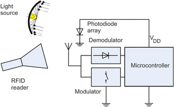
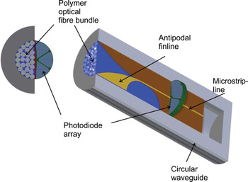
During the last few years, radio frequency identification (RFID) applications in general have been significantly growing and especially in the field of electronic article surveillance they have become one of the most important techniques. However, commonly used RFID transponder antennas, typically dipole-like antennas, suffer from performance degradation under the influence of a metallic environment especially when they are placed directly on a metallic surface. For the use of transponders in machine tools e.g. a miller, it is desirable to integrate them into that tool, as a transponder placed on the surface can be damaged easily under mechanical stress. The usage of an integratable transponder equipped with memory is a very interesting task in the field of machine tool monitoring, providing the ability to trace the product life of the tools. Hereby, the range of application is mainly limited by the transponder size, as the integration of the transponder mechanically weakens the machine tool and the volume needed for the integration of the transponder is sometimes not available. Since the antenna dimensions and the carrier frequency are reciprocally proportional, the antenna is designed to work in the Industrial, Scientific and Medical (ISM) band at 24 GHz. Owing to the high operating frequency and therefore increased free space attenuation, a classical passive RFID transponder supply concept based on a rectifier [Reference Ladan, Ghassemi, Ghiotto and Wu1] does not yield enough supply power. Thus, hybrid antenna concepts are necessary to overcome this limitation. These designs utilizing optical energy harvesting and data communication typically use solar cells directly as part of the antenna. For example, in [Reference Roo-Ons, Shynu, Ammann, McCormack and Norton2], a patch antenna is designed using solar cells as ground plane of the patch or [Reference Vaccaro, Mosig and de Maagt3] uses a solar panel as a slot antenna. These solutions or similar ones are not favorable under the constraint that the antenna structure must work in metal as a patch antenna or a cavity backed slot antenna are not well suited for the integration into a metallic machine tool. Thus, this paper presents an optically powered RFID transponder design based on a circular waveguide with a drill diameter of 8 mm, illustrated in Fig. 1. This concept supports the integration of the transponder into a metallic machine tool and the waveguide aperture can be used as an antenna. An intrinsic property of the circular aperture antenna is broad radiation characteristic and thus positioning of the reader antenna in relation to the transponder is less critical. The circular waveguide has the task of guiding light to the photodiodes for supply of the transponder while also leading the electromagnetic wave received by the waveguide aperture to the transponder circuit (reception case). Therefore, the circular waveguide is filled with a bundle of polymer optical fibers (POF) which end at a photodiode array (see Fig. 2) to power the transponder circuit which is placed behind the photodiodes. Data communication is realized via backscattering at 24 GHz. As the transponder circuit consists of a modulator and demodulator made of discrete components and a microcontroller which is used for detection of reader data and modulator control, a transition that converts the waveguide mode into microstrip mode is required to connect these discrete components. The modulator is a high electron mobility transistor that is connected in parallel to the antenna. For demodulation, an envelope detector based on beam lead Schottky diodes is used. In this paper, the focus is on optimization of the super high frequency (SHF) antenna structure and optical power supply of the transponder as shown in detail in Fig. 2. This paper is organized as follows: In Section II, the optical power supply is explained. In Section III, the waveguide to planar transition is presented containing the comparison between measurement and simulation for radiation characteristic and return loss.
The optically powered RFID transponder concept.

Design of the hybrid waveguide utilizing optical power supply and microwave antenna design (left: front view, right: perspective view).

II. OPTICAL POWER TRANSFER
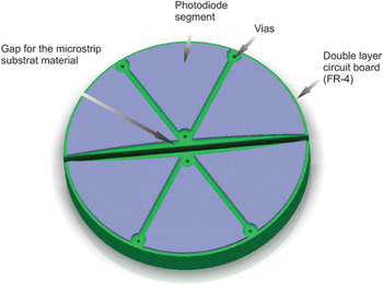
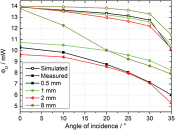
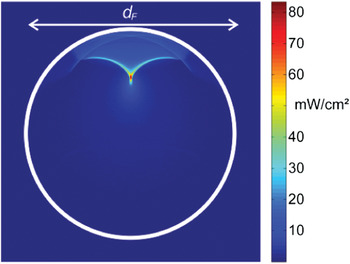
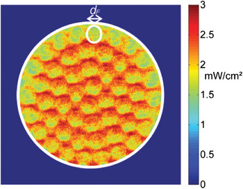
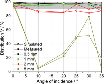
Power by light has proven to be an applicable concept using optical fibers [Reference Peña, Algora, Matías and López-Amo4] and free space [Reference Nakajima and Yokota5] as media for power transfer. In this application, the transponder shall be supplied with a voltage of at least 2 V and a power of 4 mW. The conversion of optical to electrical energy is accomplished by a circular photodiode array with a diameter of 8 mm which is placed inside the hybrid waveguide. Similar to free space applications, the light source is not fixed in relation to the waveguide aperture. Therefore, the system has to accept light from different angles with low losses. Owing to the relatively high voltage of 2 V, six photodiode segments connected in series are placed around the centre of the waveguide in a pie shape (Fig. 3). For an optimal performance of the electrical power supply all photodiodes must receive the same irradiance. As shown in Fig. 2, the microstrip line must pass through the photodiode array therefore the array is divided into two mechanical parts. The photodiode segments are fabricated using laser beam cutting; hence nearly arbitrary shapes of the array are possible. Owing to the influence of the diode segments on microstrip line impedance the diode segments form an elliptically shaped slot at the edge where the line passes through the array (see Fig. 3). The dimensions of the slot area are optimized regarding electromagnetic field distribution of the microstrip line which is concentrated near the microstrip conductor and vanishes toward the sidewalls. The major axis is 8 mm and the minor axis is 1.5 mm. The waveguide filled with the POF-bundle that is positioned in front of the photodiode array, has to feature three optical properties to work efficiently. First, it has to accept light from a wide angle of incidence, in order to avoid exact positioning between the reader light source and the transponder. Thus, easy positioning of the reader antenna and the light source is possible. Second, the waveguide has to have a high transparency for the light. And third, it has to provide an even distribution of light at the photodiode array, as the photodiodes are connected in series. Thus, the element with the lowest irradiance determines the available current and therefore the overall performance. The first property can be fulfilled by standard POFs bundled utilizing epoxy resin. The acceptance angle of these fibers is 30°. The second property can also be accomplished by using POFs. The fibers are made of polymethylmethacrylate (PMMA) which have a high transparency for visible light. They even have minimal optical attenuation at 650 nm [Reference Ziemann, Krauser, Zamzow and Daum6]. Hence, the focus is on this wavelength for the power transfer. For optimization of the optical path of the circular waveguide the system is simulated using the ray tracer software ZEMAX. A beam expanded laser is used as a source for the simulation. It is directed at the aperture of the waveguide at different angles. The irradiance and the radiant flux φD at backplane of the waveguide are determined. To verify the simulation, the radiant flux is measured. A 650 nm beam expanded laser with an irradiance of 30 mW/cm2 at the aperture of the waveguide is used to illuminate a reference photodiode behind the fiber bundle. From the short current of this photodiode the radiant flux φD is calculated. Results of these measurements and the simulation are shown in Fig. 4. Since a PMMA rod is used instead of POF with a diameter of 8 mm, measured values differ from the simulated ones at bigger angles of incidence, as the imperfect surface of the rod gains influence on the total reflection. The simulated radiant flux shows almost no losses in the dielectrically loaded waveguide. Measured results are significantly lower, though. This is due to attenuation of the epoxy, impurities, bubbles, and imperfect interfaces between air, fiber bundle, and reference diode. These losses have to be countered by light sources with higher power. Furthermore, the transparency of bundles of 1 mm fibers seems to be better than that of bundles of 2 mm and 0.5 mm fibers. For 2 mm fibers, the proportion of epoxy is higher, while at 0.5 mm the polishing of the end faces of the bundles is more difficult. For the third property of the waveguide, an even distribution of light, the number of fibers in the bundle, and hence the diameter of the fibers are relevant. Figure 5 shows the distribution for a single PMMA rod placed within the 8 mm drill hole for an angle of incidence of 20°. It becomes clear that the power is concentrated in a focal point and the segments are unevenly illuminated. Thus, the usage of a single rod is not applicable. Another example of an illumination distribution with a bundle consisting of fibers with a diameter of 1 mm for an angle of incidence of 20° is shown in Fig. 6. This example shows an almost even distribution and is therefore preferable. These two examples illustrate that the optical performance is strongly influenced by the fiber diameter. Thus, a quantitative value for the quality of the resulting distribution of the photodiode array is introduced, which is the characteristic number V and it is defined as:
 $$V=6\displaystyle{{\min \lpar \varphi _1\comma \; \varphi _2\comma \; \ldots\comma \; \varphi _6 \rpar } \over {\varphi _D }}\comma \;$$
whereas φi is the radiant flux at the photodiode segment i, while φD is the radiant flux at the whole array. V characterizes the maximal electrical current which can be expected from the whole array with respect to the radiant flux reaching the array, as the least illuminated element determines the achievable electrical current. Ideally, V would reach 100%. Practically, this is not possible, due to losses. Nevertheless, V should stay above 90% for the angle of incidence ranging from 0° to 30° which is sufficient to obtain a stable communication between the reader and the transponder placed inside the machine tool. From the simulation results of the radiant flux, V is calculated by a Matlab script. V is also measured. The short circuit current of each photodiode segment is used as representation of the radiant flux. In Fig. 7, simulated and measured results are shown. By comparing Figs. 4 and 7, it is obvious that the variations as a function of the fiber diameter are higher in Fig. 7 than in Fig. 4. Specially, the distribution of light for the 8 mm fiber is strongly dependent on the angle of incidence. This is caused by focal points and thus only a small area is well illuminated while other parts of the photodiodes are dimly lit. An example is depicted in Fig. 5. At fiber diameters of 0.5 and 1 mm the distribution stays above 90%. Therefore, these fiber diameters are preferred. Evaluation of the aforementioned three criteria results in the usage of fibers with a diameter of 1 mm. Thus, this diameter is used to form the POF-bundle and consequently the dielectric load of the waveguide.
Photodiode array for optical power supply of the transponder.

Optical power of the photodiode array as a function of the angle of incidence and fiber diameter of the single fiber for bundles with a length of 25 and 8 mm bundle diameter.

Simulated power distribution for a POF-bundle with fiber diameters of d F = 8 mm for an angle of incidence of 20°.

Simulated power distribution for a POF-bundle with fiber diameters of d F = 1 mm for an angle of incidence of 20°.

Simulated and measured power distribution on the photodiode array as a function of the angle of incidence and the single fiber diameter of fiber bundles with a length of 25 and 8 mm bundle diameter.

III. ANTENNA DESIGN
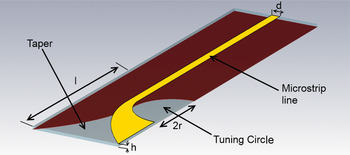
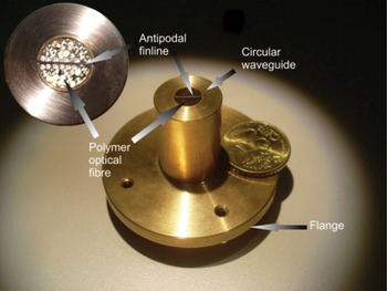
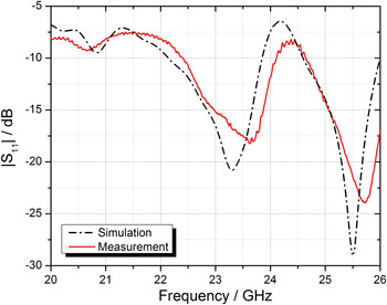
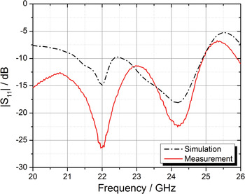
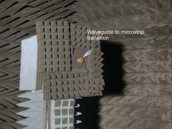
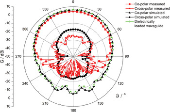
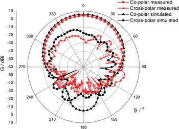
The hybrid antenna presented in this contribution is connected to the transponder circuit. Hence, a waveguide to microstrip transition is necessary to transfer the waveguide mode into a microstrip mode to connect discrete electronic devices of the modulator and demodulator. This transition should not lower the reception of optical energy in the ideal case, though. Thus, a transition that is placed in front of the photodiodes and therefore obscures them is not suitable. A transition that fulfils the aforementioned necessities is a finline structure [Reference Gupta, Garg, Bahl and Bhartia7]. Compared to other transitions e.g. unipolar finlines, antipodal finline structures suit the problem well as they transfer a waveguide mode directly to a microstrip mode and no further network, which would increase the overall dimensions of the transponder, is necessary. Since the transition must be as thin as possible to maximize the available space for the photodiodes a Rogers RT/duroid 5880 substrate material with a thickness of h = 0.254 mm, a loss tangent of tan(δ) = 0.0009, and a permittivity of ɛ r = 2.2 is used. Both the transponder circuit and the antenna are designed to a 50 Ω input impedance. Hence, the antenna feed point impedance is created with a line width of d = 0.78 mm resulting in the desired impedance to match the circuit impedance. Complex permittivity of the POF-bundle which consists of several POF and epoxy resins has a significant influence on transition design and was therefore measured using a waveguide transmission method [Reference Orlob, Kornek, Preihs and Rolfes8]. It is almost constant over the desired frequency band and has a value of approx. ɛ r = 2.44 and a loss tangent of approx. tan(δ) = 0.015. The measured values of complex permittivity are used within CST Microwave Studio to model the behavior of the POF-bundle, resulting in a well defined layout of the transition which is depicted in Fig. 8. For the sake of clarity, the POFs, photodiodes, and the waveguide are not shown. After the microstrip line has passed the photodiodes, the line structure is changed by forming a semi-circle realized by two metallization planes (see Fig. 8). The radius of the semi-circle has been changed during optimization of the transition regarding the reflection coefficient. To finally transfer the energy that is still within the substrate to the waveguide mode a taper with a square root taper function is used. The optimized overall length of the transition from the radiating aperture to the photodiode array is l = 13 mm. The length of the transition is obtained by optimizing the return loss of the antenna. The transition is fabricated using a precise etching process. In order to evaluate the antenna performance a coaxial connector is needed that has a minor influence on the return loss and the antenna gain. A Southwest Microwave connector [9] is used, as it offers superior performance in the K-band. An overall view of the realized antenna integrated into a metallic workpiece is depicted in Fig. 9. The cylinder has a length of 30 mm, a wall thickness of 6 mm, and a flange which is needed to position the antenna into an anechoic measurement chamber. The characterization of the transition can be divided into two steps. At first, the transition is placed in the dielectrically loaded waveguide containing only the POF-bundle to evaluate the accuracy of the measured permittivity of the dielectric load. The resulting comparison of the simulated and measured reflection coefficient of the transition is shown in Fig. 10. Since the measurement and simulation results fit well it infers that the permittivity of the POF-bundle was determined precisely. The second step is characterization of the realized transponder antenna including the dielectrically loaded waveguide as well as the photodiode array. The material of the photodiodes is defined as glass (ɛ r = 4.82, tan(δ) = 0.0054) and a thin metallic sheet to consider the cathode of the diode. The FR-4 substrate material (ɛ r = 4.3, tan(δ) = 0.025) on which the photodiodes are placed has a thickness of 1.5 mm. The comparison between measurement and simulation is depicted in Fig. 11. The deviation between simulation and measurement for the reflection coefficient is larger compared to the one depicted in Fig. 10. The deviation is introduced due to the number of unknowns, for example, the electrical behavior of the FR-4 and of the both not characterized for the used frequency band. Nevertheless, the curve shaping of the return loss agrees well for both measurement and simulation. An alternative approach that is almost independent of the photodiodes and the substrate material is a combination of a waveguide to substrate integrated waveguide (SIW) [Reference Djerafi, Ghiotto and Wu10] transition followed by an SIW to microstrip transition. A drawback of this solution is that two transitions are required and it is thus not investigated in this paper. Another important parameter for the transponder antenna is realized gain, since it has a significant influence on the reading range of the RFID system. Therefore, the antenna (see Fig. 9) is positioned in an anechoic chamber depicted in Fig. 12. It is obvious that the transponder antenna can achieve gain of the dielectrically loaded waveguide at best. Hence, the comparison between gain of the realized antenna and an ideal radiating circular waveguide is depicted in Fig. 13 for the E-plane which is parallel to the transition substrate. In this presentation, realized gain definition is used for the measured results and the simulated ones of the proposed antenna and the gain definition of the IEEE are used for the ideal circular waveguide as it does not include mismatch losses of the waveguide port. According to Fig. 13, the resulting difference between the proposed transition and the dielectrically loaded circular waveguide is less than 0.1 dB and the gain is approx. 6.0 dBi at 24 GHz. Another aspect is the influence of dielectric losses of the POF-bundle. Thus, the waveguide is simulated with a lossless dielectric resulting in an increased gain with a value of 6.8 dBi. The difference of 0.8 dB reduces the communication range of the RFID system. After having discussed the influence of the dielectric losses, the following section deals with the comparison between the measured and simulated gain of the realized transition. Here, Fig. 13 shows the cut for the E-plane and Fig. 14 shows the cut for the H-plane. According to these figures, the measured and simulated gain fit well. The antenna has a measured gain of approx. 4.4 dBi and it has a slightly preferred radiation direction which depends on the feeding position and resulting aperture distribution. Furthermore, the radiation characteristic shows linear radiation behavior and suppression of the cross-polar component is greater than 15 dB. The beamwidth for the H-plane is 70 and 94° for the E-plane, thus a broad radiation characteristic is obtained which enables a stable link for arbitrary positioning between reader and transponder antenna. Owing to mounting of the antenna inside the anechoic chamber, the measurement results are only valid for −90°< ϑ < 90°. The measured and the simulated gain values show a difference of approx. 1.6 dB. This deviation is probably caused by measurement inaccuracy regarding the dielectric losses of the POF-bundle as the waveguide transmission method is not well suited to evaluate them [Reference Chen, Ong, Neo, Varadan and Varadan11]. Another point is the influence of the anechoic chamber that exhibits an accuracy of approx. 1 dB, based on the experience gained from reference measurements.
Simulation model of the antipodal finline structure to excite the waveguide mode.

The testbed consisting of a brass cylinder with integrated antenna.

Comparison between simulated and measurement reflection coefficient for the dielectrically loaded waveguide to microstrip transition.

Comparison between simulated and measured reflection coefficient for the realized waveguide to microstrip transition including the photodiode array.

Anechoic chamber for gain measurement.

Measured and simulated gain pattern of the antenna structure for the E-plane of the transition and an ideal circular waveguide.

Measured and simulated gain pattern of the antenna structure for the H-plane.

IV. CONCLUSION
This paper presents a hybrid antenna for a miniaturized optically powered 24 GHz RFID transponder. The antenna allows an easy integration of the transponder into metallic workpieces, e.g. a machine tool. Therefore, the aperture of a circular waveguide is used as antenna as well as optical waveguide to guide the incident light to a photodiode array. The optical components of the transponder are optimized for good power transfer and a uniform distribution of the light at the photodiode array even for different incident angles of the optical signal. For excitation of the waveguide mode an antipodal finline structure is used as its influence is minimal on optical performance. The circular waveguide is dielectrically loaded and the permittivity of the POF-bundle is therefore characterized. Followed by the characterization of the POF-bundle, the design of the transition and the resulting antenna parameters are shown.
ACKNOWLEDGMENT
The authors want to thank the Deutsche Forschungsgemeinschaft (DFG) for the financial support of this work in the framework of the Collaborative Research Centre 653, especially E. Batzdorfer for fabricating the mechanical parts of the transponder and the Laser Center Hannover for laser cutting the photodiodes.
 Johannes Meyer was born in Bremen, Germany, in 1982. He received his Dipl.-Ing. degree in electrical engineering from the Leibniz Universität Hannover, Hannover, Germany, in 2009. Since then, he has been a Research Assistant with the Institute of Radiofrequency and Microwave Engineering, Leibniz Universität Hannover and he is currently working toward the Ph.D. degree in microwave engineering. His current research interests include RF identification in the UHF and SHF band especially, the development of hybrid RFID systems including antenna and discrete microwave circuit design. Mr Meyer was the recipient of the RFID-Systech 2010 best paper award.
 Stefan Franke received his Dipl.-Ing. degree in electrical engineering from the Technische Universität Chemnitz in 2005. Till 2012, he was a Research Assistant at the Institute for Transport and Automation Technology of the Leibniz Universität Hannover. His main topics have been optical power transfer and polymer optics. In 2011, he received a doctor's degree (Dr.-Ing.) in mechanical engineering from the Leibniz Universität Hannover. Currently, he is construction engineer for interior lighting solution at the Volkswagen AG, Wolfsburg.
 Bernd Geck was born in Oldenburg, Germany in 1959. He received a diploma in electrical engineering and the Ph.D. degree from the Leibniz Universität Hannover. From 1987 to 1991 he worked as a research assistant and since 1991 he has been a senior engineer and manager of the Institute of Radiofrequency and Microwave Engineering. His current research activities are focused on high frequency measuring and sensor systems and RFID/NFC applications.
 Ludger Overmeyer was born in 1964. He studied electrical engineering at the Leibniz Universität Hannover and, subsequently, worked as a research associate at the Laser Zentrum Hannover e.V. (LZH). After receiving his doctorate in mechanical engineering he worked as executive manager of research and development in the field of machine and plant manufacture for the semiconductor industry. Since 2002, he has headed the Institute of Transport and Automation Technology (ITA) at Leibniz Universität Hannover. In 2003, he became a member of the board of Production Engineering Center Hannover. He is a founding member of the logistics journal (WGTL) and has reviewed several articles since 2004. Furthermore, he is an evaluator for the German Research Foundation (DFG). In 2007, he became a member of the management board of the IPH – Institute of Integrated Production Hannover. His primary research areas include automation, control technology, transport engineering, RFID technology, microelectronics, and Laser technology.