1. Introduction
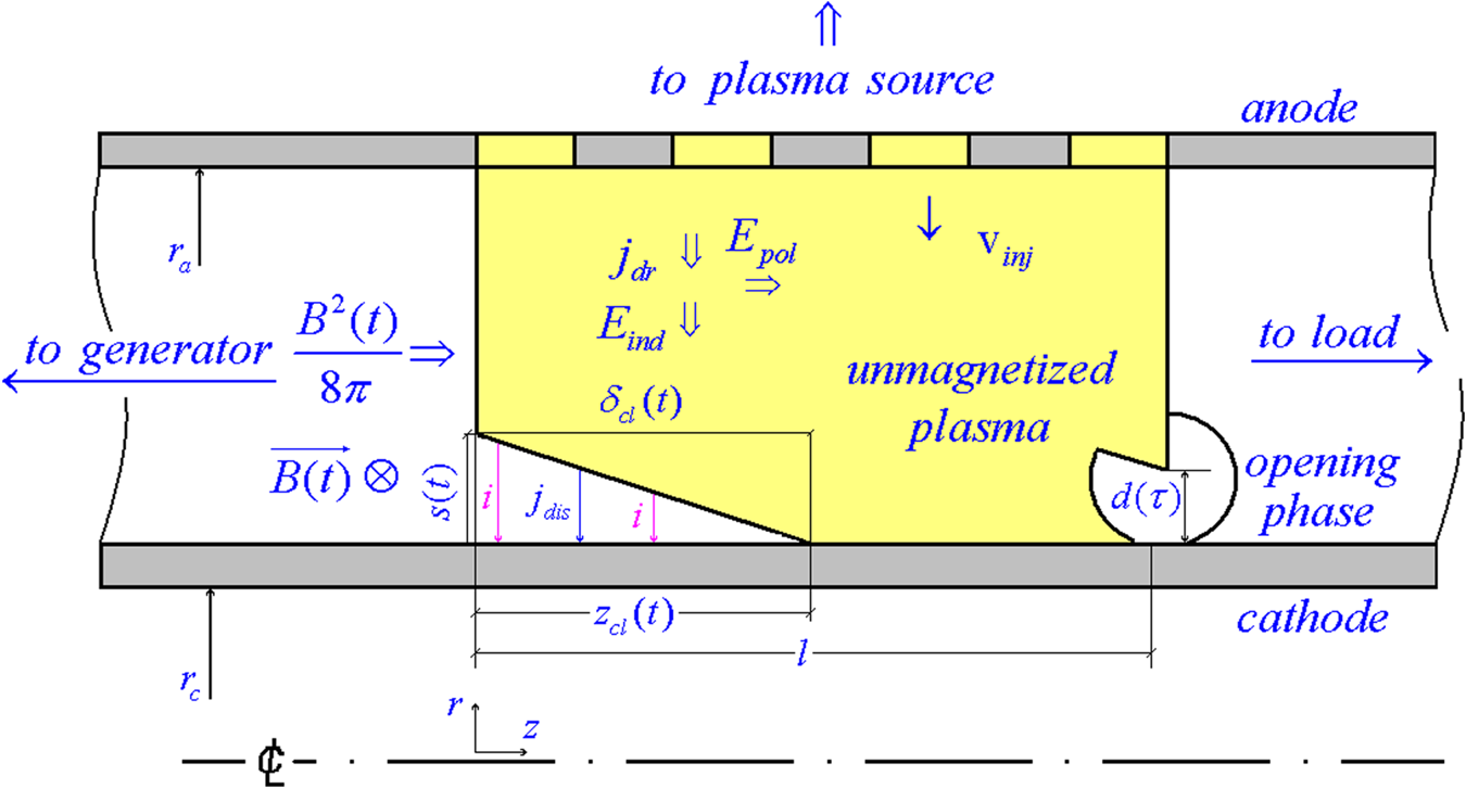
The incredibly simple design of a plasma opening switch (POS) makes such a device very attractive for terawatt pulsed power technologies (Ware et al. Reference Ware, Filios, Gullickson, Rowley, Schneider, Summa and Vitkovitsky1997). Conventionally, it is a vacuum coaxial segment filled with a fully ionized plasma (figure 1) which, being injected into the segment with a directed velocity  ${v_{\textrm{inj}}}$, can provide conduction to an inductive energy store (closed state) with fast energy delivery to a load (open state).
Switch schematic.

By now, many studies have been performed to verify the technology of producing terawatt pulses in POS-based systems. In particular, two radically different forms of scaling have been identified for the conduction current  ${I_\textrm{c}}$ depending on the plasma density in this type of switch. According to one of the concepts (Ottinger, Goldstein & Meger Reference Ottinger, Goldstein and Meger1984), the conduction current in a nanosecond POS is determined by the current of space charge-limited electron emission such that
 ${I_\textrm{c}} = {j_{\textrm{sat}}}S$, where
 $S = 2{\rm \pi} {r_\textrm{c}}l$ is the emitting area of a cathode of radius
 ${r_\textrm{c}}$ and l is the length of a uniform plasma bridge along the cathode. The emission current density is assumed equal to the bipolar saturation current
 ${j_{\textrm{sat}}}$ determined by the Langmuir relation
 ${j_{\textrm{sat}}}/{j_\textrm{i}} \simeq {j_\textrm{e}}/{j_\textrm{i}} = {({m_\textrm{i}}/Zm)^{1/2}}$ with
 ${j_\textrm{i}} = Ze{n_\textrm{i}}{v_{\textrm{inj}}}$ being the ion current density due to cathode-directed plasma motion. Here,
 ${m_\textrm{i}}$ and m are the ion and electron masses,
 $Ze$ and e are the ion and electron charges and
 ${n_\textrm{i}} = n/Z$ and
 ${v_{\textrm{inj}}}$ are the density of ions and their directed velocity. Thus, the concept suggests that the conduction current in a nanosecond switch is
 ${I_\textrm{c}} \propto n$ and is independent of the rate of rise of its current
 $\dot{I}$. However, in a microsecond POS, the conduction current does depend on the rate of current rise
 ${I_\textrm{c}} \propto {\dot{I}^{1/2}}$ and on the mass density of plasma
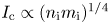 ${I_\textrm{c}} \propto {({n_\textrm{i}}{m_\textrm{i}})^{1/4}}$ (Rix et al. Reference Rix, Parks, Shannon, Thompson and Waisman1991; Weber et al. Reference Weber, Commisso, Goodrich, Grossmann, Hinshelwood, Ottinger and Swanecamp1995).
The evolution of the conduction scaling from  ${I_\textrm{c}} \propto n$ to
 ${I_\textrm{c}} \propto {n^{1/4}}$ is determined by the mechanism of magnetic field transport through the switch plasma. Research data (Weber et al. Reference Weber, Commisso, Cooperstein, Grossmann, Hinshelwood, Mosher, Neri, Ottinger and Stephanakis1987) suggest that plasma erosion (loss of plasma mass as ions move to the cathode) occurs in a nanosecond POS almost from the onset of current rise, allowing its current channel to reach the downstream plasma edge. As the conduction time is increased, plasma aggregation under magnetic field pressure (magnetic piston approximation) starts dominating. As a result, plasma erosion is possible only when the current channel reaches the downstream plasma edge.
The above forms of scaling are phenomenological and ignore the dynamics of processes in a switch during the rise of its current. The first form of scaling assumes a priori that there is a current flowing in the near-cathode layer in the space charge-limited bipolar mode. The second one implies a zero-dimensional approximation with a perfectly conducting magnetic piston. In this paper, a unified approach is proposed for understanding the operation of any switch. The paper analyses the current transport in a POS with account of the plasma density and rate of current rise. Estimates of the current channel dynamics in collisionless and collisional plasmas are presented including the magnetic field velocity, electron flow velocity, conduction current and channel conductivity across the magnetic field. These estimates are used to determine the rate of rise of the switch resistance and the peak voltage in the phase of current cutoff. The peak voltage obtained in calculations is compared with its experimental values recorded in experiments on mega-ampere current switching. A procedure is also presented for calculating the switch parameters to obtain the maximum possible voltage in the phase of current cutoff.
The approach stems from the physics of plasma processes common to all switches. In all switches, irrespective of the conduction time, electrons are magnetized as the magnetic field grows. However, the magnetization time strongly depends on the collisional properties of the plasma, which are determined by its density and electron temperature. If the magnetization is faster than electron–ion collisions, the plasma is collisionless such that the depth of magnetic field penetration is limited by a value of the order of the collisionless electron skin layer  $c/{\omega _{\textrm{pe}}}$, where
 ${\omega _{\textrm{pe}}} = {(4{\rm \pi} n{e^2}/m)^{1/2}}$ is the electron plasma frequency. In a collisional plasma with a conductivity
 $\sigma $, the depth of magnetic field penetration is determined by the magnetic viscosity
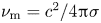 ${\nu _\textrm{m}} = {c^2}/4{\rm \pi} \sigma $.
2. Conduction phase
2.1. Collisionless plasma
Experiments suggest that the magnetic field in a nanosecond switch  $B(t)$ is transported along its axis with a roughly constant velocity (within a current pulse) equal to the ratio of initial bridge length to conduction time:
 ${u_{\textrm{cl}}} = l/{t_\textrm{c}}$ (Mosher et al. Reference Mosher, Grossmann, Ottinger and Colombant1987). The plasma is taken to be collisionless and cold for simplicity while having a directed velocity. For this plasma, we can use the approximation of single-particle motion. As the magnetic field propagates in the plasma, it induces an electric field
 ${E_{\textrm{ind}}}(t) = {u_{\textrm{cl}}}B(t)/c$ radial from anode to cathode (figure 1). In this induced electric field, the velocity of ions increases slightly. Due to the mass difference the directed velocity of electrons
 ${v_{\textrm{inj}}}$ rapidly decreases and they start accelerating towards the anode. Integration of the equation of electron motion in the field
 ${E_{\textrm{ind}}}(t)$ for a linearly increasing magnetic field
 $B(t) = \dot{B}t$ gives that the velocity of electrons is reversed at the point in time
 ${\tau _\textrm{r}} = {(2{v_{\textrm{inj}}}mc/{u_{\textrm{cl}}}e\dot{B})^{1/2}}$. At later times, their distance from the cathode reaches
 $s(t) = e\dot{B}{u_{\textrm{cl}}}{(t - {\tau _\textrm{r}})^3}/6mc$, and their Larmor radius
 ${r_\textrm{L}}(t) = {u_{\textrm{cl}}}(t - {\tau _\textrm{r}})/2$ calculated for the current velocity
 $\dot{s}(t)$ grows. The magnetization of electrons is represented by the equality of the Larmor radius to
 $s({\tau _{\textrm{cl}}})$ at the time point
 ${\tau _{\textrm{cl}}} = {(3mc/e\dot{B})^{1/2}}$. Hereinafter,
 ${\tau _\textrm{r}}$ is neglected because the ratio
 ${\tau _\textrm{r}}/{\tau _{\textrm{cl}}} = {(2{v_{\textrm{inj}}}/3{u_{\textrm{cl}}})^{1/2}}$ for real velocities is, as a rule, much lower than unity.
The radial current density at  $t \gt {\tau _{\textrm{cl}}}$ is taken to be
 ${j_{\textrm{dr}}} = en{v_{\textrm{dr}}}$ (figure 1), where the electron drift velocity is algebraically given by
 ${v_{\textrm{dr}}} = \dot{s}({\tau _{\textrm{cl}}}) = 3{u_{\textrm{cl}}}/2$. This assumption agrees with experimental data on the penetration of a magnetic field into a plasma with a roughly constant current density (Weber et al. Reference Weber, Commisso, Cooperstein, Grossmann, Hinshelwood, Mosher, Neri, Ottinger and Stephanakis1987). The drift of electrons occurs in crossed magnetic and axial polarization electric fields
 ${E_{\textrm{pol}}}(t) = {j_{\textrm{dr}}}B(t)/enc$ (Grossmann et al. Reference Grossmann, Ottinger, Nery and Drobot1986; Grossmann, Ottinger & Mason Reference Grossmann, Ottinger and Mason1989). The polarization field arises due to charge separation during the motion of electrons in the current channel. It balances the Ampere force which acts on the electrons and which is proportional to the product of the current density and magnetic induction. The ratio between the polarization and induced fields is constant:
 ${E_{\textrm{pol}}}(t)/{E_{\textrm{ind}}}(t) = 3/2$. The ratio holds until electrons with a velocity
 ${v_{\textrm{dr}}}$ cross the interelectrode gap. During this time, the magnetic field continues its linear propagation along the cathode with the generation of induced and polarization electric fields in the plasma volume (figure 1).
From  ${I_\textrm{c}} = {j_{\textrm{dr}}}S$ and
 ${I_\textrm{c}} = \dot{I}l/{u_{\textrm{cl}}}$ it follows that the magnetic field velocity is
 ${u_{\textrm{cl}}} = {(\dot{B}c/6{\rm \pi} en)^{1/2}}$, where
 $\dot{B} = 2\dot{I}/c{r_\textrm{c}}$. The switch conduction current is given by the formula
 \begin{equation}{I_\textrm{c}} = {(3{\rm \pi} en\dot{I}{r_\textrm{c}}{l^2})^{1/2}}.\end{equation}
For the thus obtained velocity of field penetration, we have  $s({\tau _{\textrm{cl}}}) = {r_\textrm{L}}({\tau _{\textrm{cl}}}) = c/\sqrt 2 {\omega _{\textrm{pe}}}$. The depth of field penetration along the cathode
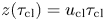 $z({\tau _{\textrm{cl}}}) = {u_{\textrm{cl}}}{\tau _{\textrm{cl}}}$ and the current channel width determined as
 ${\delta _{\textrm{cl}}} = \dot{I}{\tau _{\textrm{cl}}}/2{\rm \pi} {r_\textrm{c}}{\,j_{\textrm{dr}}}$ are equal to
 $\sqrt 2 c/{\omega _{\textrm{pe}}}$, i.e. are of the order of the electron collisionless skin layer. Because
 $c/{\omega _{\textrm{pe}}} \ll {r_\textrm{c}}$, we can well use the magnetic field at the cathode for estimation of
 ${\tau _{\textrm{cl}}}$ and for calculation of other switch parameters. During the time
 ${\tau _{\textrm{cl}}}$, the drift velocity gained by electrons is much lower than the velocity of light, allowing a non-relativistic treatment of the electron dynamics in the conduction phase.
It should be noted that the switch current  ${I_\textrm{s}} = \dot{I}{\tau _{\textrm{cl}}}$ at the time point
 ${\tau _{\textrm{cl}}}$ is equal to the self-magnetic insulation current of non-relativistic electrons
 ${I_{\textrm{mi}}}({\tau _{\textrm{cl}}}) = (m{c^3}/\sqrt 2 e){(e{U_\textrm{s}}({\tau _{\textrm{cl}}})/m{c^2})^{1/2}}{r_\textrm{c}}/s({\tau _{\textrm{cl}}})$, which can be verified by direct substitution of the quantities
 ${I_\textrm{s}}({\tau _{\textrm{cl}}}) = {I_{\textrm{mi}}}({\tau _{\textrm{cl}}})$ using the condition
 $e{U_\textrm{s}}({\tau _{\textrm{cl}}}) = m{\dot{s}^2}({\tau _{\textrm{cl}}})/2$. The fact that the gap becomes magnetically insulated at
 ${\tau _{\textrm{cl}}}$ means that when a secondary plasma appears at the cathode, its electrons cannot cross the gap formed by primarily injected plasma electrons moving off the cathode. The motion of electrons off the cathode uncovers an ion layer or a so-called charge-uncompensated ion matrix layer, which needs a separate study to trace its evolution to the state of space charge-limited ion conduction (Lieberman & Lichtenberg Reference Lieberman and Lichtenberg2005). The only note here is that the electric field dynamics of the ion space charge
 ${E_{\textrm{sh}}}(\varDelta ,t) = 4{\rm \pi} Ze{n_\textrm{i}}(\varDelta - s(t))$, where
 $\varDelta = r - {r_\textrm{c}}$ is the intermediate coordinate between the cathode and
 ${r_\textrm{c}} + s(t)$, can be responsible for the generation of displacement current
 ${j_{\textrm{dis}}}(t) = \partial {E_{\textrm{sh}}}(\varDelta ,t)/4{\rm \pi} \partial t$ whose conjugation with conduction current
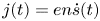 $j(t) = en\dot{s}(t)$ will make the continuity equation valid for the near-cathode ion layer (figure 1).
For magnetized electrons at  $t \gt {\tau _{\textrm{cl}}}$, we can introduce the effective conductivity
 $\varSigma (t) = {j_{\textrm{dr}}}/{E_{\textrm{ind}}}(t) = 3enc/2\dot{B}t$. This coefficient establishes the relation between the induced electric field and the current density co-directional with it, which is quite acceptable. The derived expression can be reduced to
 $\Sigma (t) = {\sigma _0}/{\omega _\textrm{e}}(t){\tau _{\textrm{cl}}}$ showing that the current channel conductivity is suppressed by a factor of
 ${\omega _\textrm{e}}(t){\tau _{\textrm{cl}}}$ with increasing magnetic field. Here,
 ${\omega _\textrm{e}}(t){\tau _{\textrm{cl}}}$ is the magnetization parameter (also called the Hall parameter),
 ${\omega _\textrm{e}}(t) = e\dot{B}t/mc$ is the electron cyclotron frequency and
 ${\sigma _0} = 3n{e^2}{\tau _{\textrm{cl}}}/2m = 3\omega _{\textrm{pe}}^2{\tau _{\textrm{cl}}}/8{\rm \pi} $. The effective conductivity can be also expressed as
 $\Sigma (t) = {c^2}/4{\rm \pi} u_{\textrm{cl}}^2t$. In this case, for
 ${\nu _\textrm{m}}(t) = {c^2}/4{\rm \pi} \varSigma (t)$ being the magnetic viscosity, the current channel width in the plasma volume
 ${\delta _{\textrm{cl}}}(t) = {({\nu _\textrm{m}}(t)t)^{1/2}} = {u_{\textrm{cl}}}t$ increases synchronously with the depth of field penetration along the cathode
 ${z_{\textrm{cl}}}(t) = {u_{\textrm{cl}}}t$ (figure 1). This, without accounting for possible axial plasma displacement, explains the current channel broadening up to half the initial bridge length in experiments with nanosecond switches (Weber et al. Reference Weber, Commisso, Cooperstein, Grossmann, Hinshelwood, Mosher, Neri, Ottinger and Stephanakis1987).
2.2. Collisional plasma
In a collisional plasma with an increasing magnetic field, the Larmor radius of an electron with a thermal velocity compares with the free path subject to the condition  ${\omega _\textrm{e}}(t) \simeq {\nu _{\textrm{ei}}}$, where
 ${\nu _{\textrm{ei}}}$ is the electron–ion collision frequency. According to this condition, the magnetization of electrons and the onset of their drift fall on the time point
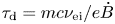 ${\tau _\textrm{d}} = mc{\nu _{\textrm{ei}}}/e\dot{B}$. Here, unlike the collisionless plasma, the magnetization time
 ${\tau _\textrm{d}}$ depends on the collision frequency. For field diffusion into such a conductor, the current density at its generator-facing boundary is given exactly by
 ${j_\textrm{d}}(t) = \dot{B}{(\sigma t)^{1/2}}/{\rm \pi} $ (Knoepfel Reference Knoepfel1970) with a logarithmically weak density dependence of the Spitzer plasma conductivity
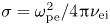 $\sigma = \omega _{\textrm{pe}}^2/4{\rm \pi} {\nu _{\textrm{ei}}}$ because
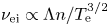 ${\nu _{\textrm{ei}}} \propto \Lambda n/T_\textrm{e}^{3/2}$, where
 ${T_\textrm{e}}$ is the electron temperature and
 $\varLambda $ is the Coulomb logarithm of the number of particles in a Debye sphere (Braginskii Reference Braginskii1965). The current density at the time point
 ${\tau _\textrm{d}}$ determines the drift velocity of magnetized electrons
 ${v_{\textrm{dr}}} = {{\rm \pi} ^{ - 1}}{(\dot{B}c/en)^{1/2}}$ at
 $t \gt {\tau _\textrm{d}}$. Then, from the equality
 ${I_\textrm{c}} = {j_{\textrm{dr}}}S = \dot{I}l/{u_\textrm{d}}$ it follows that the magnetic field velocity is
 ${u_\textrm{d}} = {(\dot{B}c/16en)^{1/2}}$ and that the switch conduction current can be given by the formula
 \begin{equation}{I_\textrm{c}} = {(8en\dot{I}{r_\textrm{c}}{l^2})^{1/2}}.\end{equation}
It should be noted that despite the dependence of  ${\tau _\textrm{d}}$ on the collision frequency, the velocities of magnetic field penetration
 ${u_{\textrm{cl}}}$ and
 ${u_\textrm{d}}$ are slightly different in their numerical factor. Finally, conduction current (2.2) is given by a formula similar to (2.1).
For the field velocity determined in this way, the component of the induced electric field  ${E_{\textrm{ind}}}(t) = {u_\textrm{d}}B(t)/c$ becomes higher than the component
 $E(t) = {j_\textrm{d}}(t)/\sigma $ governed by the rate of rise of the magnetic field
 $B(t) = \dot{B}t$ even at
 $t = 16{\tau _\textrm{d}}/{{\rm \pi} ^2}$ and is then dominating. In this case, compared to the collisionless plasma, the ratio
 ${E_{\textrm{pol}}}(t)/{E_{\textrm{ind}}}(t)$ decreases to
 $4/{\rm \pi} $. The effective plasma conductivity is
 $\varSigma (t) = {j_{\textrm{dr}}}/{E_{\textrm{ind}}}(t) = {\sigma _0}/{\omega _\textrm{e}}(t){\tau _{\textrm{ei}}}$, where
 ${\sigma _0} = 4\sigma /{\rm \pi} $,
 ${\tau _{\textrm{ei}}} = \nu _{\textrm{ei}}^{ - 1}$ and
 ${\omega _\textrm{e}}(t){\tau _{\textrm{ei}}}$ is the electron magnetization parameter. Because
 $\varSigma (t) = {c^2}/4{\rm \pi} u_\textrm{d}^2t$ as before, the current channel width in the plasma volume
 ${\delta _\textrm{d}}(t) = {({\nu _\textrm{m}}(t)t)^{1/2}} = {u_\textrm{d}}t$ increases synchronously with the depth of magnetic field diffusion along the cathode
 ${z_\textrm{d}}(t) = {u_\textrm{d}}t$.
At the same time, the polarization field responsible for radial electron transfer from the cathode to the anode (across the strong magnetic field) is also responsible for axial ion acceleration. In the magnetic piston approximation, the acceleration is given by  $a = \dot{B}/{(12{\rm \pi} {m_\textrm{i}}{n_\textrm{i}})^{1/2}}$ (Loginov Reference Loginov2011) without regard for the piston (plasma) mass lost due to radial ion motion to the cathode. In this case, the piston velocity
 ${u_{\textrm{mp}}}(t) = at$ increases linearly with time, providing an axial plasma shift
 ${z_{\textrm{mp}}}(t) = a{t^2}/2$. The arrival of the piston at the downstream plasma edge determines the time and the current of conduction:
 \begin{equation}{I_\textrm{c}} = {(12{\rm \pi} {n_\textrm{i}}{m_\textrm{i}}{c^2})^{1/4}}{(\dot{I}{r_\textrm{c}}l)^{1/2}}.\end{equation}
Formula (2.3) as applied to an experiment with a finite current channel conductivity and a piston velocity greater than the ion sound velocity is discussed elsewhere (Loginov Reference Loginov2011). Certainly, such conditions influence the channel structure but they do not cancel its diffusion formation as a channel pressed to the magnetic piston plane at high initial plasma conductivity. Substitution of  ${\tau _{\textrm{mp}}}(t) = {(c/{u_{\textrm{mp}}}(t))^2}/4\sigma $ in the current density
 ${j_\textrm{d}}({\tau _{\textrm{mp}}}(t)) = \dot{B}{(\sigma {\tau _{\textrm{mp}}}(t))^{1/2}}/{\rm \pi} $ gives
 $I(t) = {j_\textrm{d}}({\tau _{\textrm{mp}}}(t))S(t) = \dot{I}(2{z_{\textrm{mp}}}(t)/{u_{\textrm{mp}}}(t))$ with
 $S(t) = 2{\rm \pi} {r_\textrm{c}}{z_{\textrm{mp}}}(t)$ for the switch current. On completion of the conduction phase at
 ${t_\textrm{c}} = 2l/{u_{\textrm{mp}}}({t_\textrm{c}})$, this formula is reduced to expression (2.3). The above formal substitution is justified because the depth of field diffusion
 ${({\nu _m}{\tau _{\textrm{mp}}})^{1/2}}$ for the time
 ${\tau _{\textrm{mp}}}(t)$ at
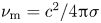 ${\nu _\textrm{m}} = {c^2}/4{\rm \pi} \sigma $ is of the order of an axial piston shift
 ${u_{\textrm{mp}}}(t){\tau _{\textrm{mp}}}$ with a slight increase in the velocity
 ${u_{\textrm{mp}}}(t)$ during
 ${\tau _{\textrm{mp}}}(t)$. This means that for an axially moving piston, the magnetization of electrons and their motion off the cathode are constantly replenished by undisturbed plasma aggregation. Thus, no displacement current is needed to explain the closed discharge current in a narrow region adjacent to the cathode. Besides, in the case of axial plasma motion, the cathode is prevented from unlimited emissivity, and the current channel from broadening up to the initial bridge length which would be possible at magnetic field velocities
 ${u_{\textrm{cl}}}$ or
 ${u_\textrm{d}}$.
At the time point  ${\tau _{\textrm{mp}}}(t)$, the current density is
 ${j_{\textrm{dr}}}({\tau _{\textrm{mp}}}(t)) = \dot{B}c/2{\rm \pi} {u_{\textrm{mp}}}(t)$, and the electron drift velocity can be estimated as
 ${v_{\textrm{dr}}}(t) = {j_{\textrm{dr}}}({\tau _{\textrm{mp}}}(t))/e\xi (t)n$, where
 $\xi = {n_{\textrm{ch}}}(t)/n$ represents the build-up of plasma density in the current channel due to aggregation. Because of accelerated piston motion, the ratio
 ${E_{\textrm{pol}}}(t)/{E_{\textrm{ind}}}(t) = {v_{\textrm{dr}}}(t)/{u_{\textrm{mp}}}(t)$ is no longer constant and decreases as the plasma is aggregated. The effective plasma conductivity
 $\varSigma (t) = {j_{\textrm{dr}}}({\tau _{\textrm{mp}}}(t))/{E_{\textrm{ind}}}(t) = {(c/{u_{\textrm{mp}}}(t))^2}/2{\rm \pi} t$ is inversely proportional to
 ${t^3}$. In the form
 $\varSigma (t) = 6({m_\textrm{i}}/Zm)({\tau _{\textrm{ei}}}/t)\sigma /{(\omega (t){\tau _{\textrm{ei}}})^2}$, it gives an inverse quadratic dependence of the current channel conductivity on the electron magnetization parameter.
The above analysis of current transport gives very simple scaling forms of conduction current (2.1)–(2.3). They are convenient for comparison with experiments as they are alike in their dependences on the rate of magnetic field rise while differing radically in their plasma density dependences. In any case, however, the magnetic viscosity in the plasma volume is determined not by the Spitzer conductivity but by the effective conductivity suppressed with respect to the Spitzer one by a factor equal to the magnetization parameter raised to one or another power. It is this feature that allows magnetic field penetration deep into a highly ionized plasma. Thus, there is no need to appeal to different types of instabilities turbulizing the plasma and decreasing its conductivity. At the same time, the analysis does not discard numerical simulations which can provide detailed information on the plasma dynamics in a fast rising magnetic field (Cassany & Grua Reference Cassany and Grua1995; Schumer et al. Reference Schumer, Swanecamp, Ottinger, Commisso, Weber, Smithe and Ludeking2001).
3. Opening phase
When the current channel reaches the downstream plasma edge, current switching begins. The process is assisted by electrons moving off the cathode and forming a vacuum gap for magnetic flow to the load. For a constant electron drift velocity, the vacuum gap is  $d(\tau ) = {v_{\textrm{dr}}}\tau $, where the time
 $\tau = t - {t_\textrm{c}}$ is counted from the point of completion of the conduction phase (figure 1).
As the load gets current, the switch current  ${I_\textrm{s}}(\tau )$ decreases exponentially. On interruption of the current in the inductive store, the central electrode of the switch takes on a high negative potential. In this case, the current required for magnetic insulation of electrons with an energy corresponding to the cathode potential is given in the one-particle approximation by the formula
 ${I_{\textrm{mi}}}(\tau ) = (m{c^3}/2e){({\gamma ^2} - 1)^{1/2}}{r_\textrm{c}}/d(\tau )$ (Ottinger et al. Reference Ottinger, Goldstein and Meger1984), where
 $\gamma = 1 + e{U_\textrm{s}}(\tau )/m{c^2}$ is the relativistic gamma factor for the arising voltage
 ${U_\textrm{s}}(\tau )$. As the switch current
 ${I_\textrm{s}}(\tau )$ tends to
 ${I_{\textrm{mi}}}(\tau )$ and the gap
 $d(\tau )$ grows, the voltage at a certain time point
 ${\tau _\textrm{m}}$ reaches its maximum. Nevertheless, the condition
 ${I_\textrm{s}}({\tau _\textrm{m}}) \approx {I_{\textrm{mi}}}({\tau _\textrm{m}})$ (Ottinger et al. Reference Ottinger, Goldstein and Meger1984), being phenomenological, appears useful for estimating the rate of rise of the switch resistance. In the ultra-relativistic case of practical interest, the voltage peak is
 ${U_\textrm{s}}({\tau _\textrm{m}}) \approx {I_\textrm{s}}({\tau _\textrm{m}})(2/c)(d({\tau _\textrm{m}})/{r_\textrm{c}})$ from which the switch resistance is
 ${R_\textrm{s}}({\tau _\textrm{m}}) = 2d({\tau _\textrm{m}})/c{r_\textrm{c}}$ and the rate of its rise can be taken as
 ${\dot{R}_\textrm{s}} = {R_\textrm{s}}({\tau _\textrm{m}})/{\tau _\textrm{m}} = 2{v_{\textrm{dr}}}/c{r_\textrm{c}}$. The resistance
 ${\dot{R}_\textrm{s}}$ is determined by the ratio of the electron drift velocity
 ${v_{\textrm{dr}}}$ to the cathode radius. For a switch with a specified rate of current rise and known plasma density, calculation of
 ${v_{\textrm{dr}}}$ gives
 ${\dot{R}_\textrm{s}}$, and
 ${\dot{R}_\textrm{s}}$ allows calculation of the peak voltage on current cutoff and the time it takes for the voltage to peak.
From a circuit analysis for a linearly increasing switch resistance (Loginov Reference Loginov2008), it follows that the voltage peaks at  ${\tau _\textrm{m}} = {c^{ - 1}}{({L_\textrm{t}}/{\dot{R}_\textrm{s}})^{1/2}}$ with
 ${L_\textrm{t}} = {L_\textrm{g}}{L_\textrm{l}}/({L_\textrm{g}} + {L_\textrm{l}})$, where
 ${L_\textrm{g}}$ and
 ${L_\textrm{l}}$ are the store and load inductances, respectively. Then, the resistance is
 ${R_\textrm{s}}({\tau _\textrm{m}}) = {c^{ - 1}}{({L_\textrm{t}}{\dot{R}_\textrm{s}})^{1/2}}$ and the peak voltage is
 ${U_\textrm{s}}({\tau _\textrm{m}}) = {R_\textrm{s}}({\tau _\textrm{m}}){I_\textrm{s}}({\tau _\textrm{m}})$.
Of interest are functional dependences of the peak voltage  ${U_\textrm{m}}$ on the switch parameters and on the rate of current rise. For the conduction current determined by formula (2.1) or (2.2), the electron drift velocity is
 ${v_{\textrm{dr}}} \sim u \propto {(\dot{I}/n{r_\textrm{c}})^{1/2}}$, and hence
 ${\dot{R}_\textrm{s}} \propto {\dot{I}^{1/2}}/{n^{1/2}}r_\textrm{c}^{3/2}$ and
 ${U_\textrm{m}} \propto {I_\textrm{c}}{\dot{I}^{1/4}}/{n^{1/4}}r_\textrm{c}^{3/4}$. With the conduction current instead of the plasma density, the scaling is
 ${U_\textrm{m}} \propto {({I_\textrm{c}}\dot{I}l/{r_\textrm{c}})^{1/2}}$ showing that the peak voltage is proportional to
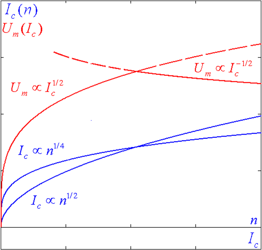
 $I_\textrm{c}^{1/2}$ (figure 2).
Generalization of the voltage scaling.

On the contrary, for plasma aggregation on completion of conduction, we have  ${u_{\textrm{mp}}}({t_\textrm{c}}) = 2l/{t_\textrm{c}} = 2l\dot{I}/{I_\textrm{c}}$, and the electron drift velocity exclusive of the plasma density build-up
 $\xi $ is expressed simply as
 ${v_{\textrm{dr}}}({t_\textrm{c}}) = {I_\textrm{c}}/e\xi nS$, where
 $S = 2{\rm \pi} {r_\textrm{c}}l$ but
 ${I_\textrm{c}}$ is given by (2.3). In this case,
 ${\dot{R}_\textrm{s}} \propto {\dot{I}^{1/2}}/\xi {n^{3/4}}r_\textrm{c}^{3/2}{l^{1/2}}$ and
 ${U_\textrm{m}} \propto {\dot{I}^{3/4}}{l^{1/4}}/{\xi ^{1/2}}{n^{1/8}}r_\textrm{c}^{1/4}$. With the exclusion of the plasma density, the scaling is
 ${U_\textrm{m}} \propto \dot{I}{l^{1/2}}/{\xi ^{1/2}}I_\textrm{c}^{1/2}$ showing that the peak voltage is inversely proportional to
 $I_\textrm{c}^{1/2}$ (figure 2).
Thus, depending on the conduction time, the voltage scaling varies from its ascending form  ${\propto} I_\textrm{c}^{1/2}$ in nanosecond switches to its descending form
 ${\propto} I_\textrm{c}^{ - 1/2}$ in microsecond switches. Additionally, the peak voltage is decreased due to plasma aggregation and associated increase in the plasma density:
 ${U_\textrm{m}} \propto {\xi ^{ - 1/2}}$. Figure 2 clearly demonstrates that the increase in the plasma density is reasonable up to a certain critical value at which the increase in the conduction current does not increase the voltage on its interruption.
4. Discussion and comparison with experiments
The plasma of an opening switch can be considered collisionless if the electron magnetization time  ${\tau _{\textrm{cl}}}$ is shorter than the electron–ion collision time
 ${\tau _{\textrm{ei}}}$. This condition limits the plasma density by the inequality
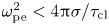 $\omega _{\textrm{pe}}^2 \lt 4{\rm \pi} \sigma /{\tau _{\textrm{cl}}}$ which depends on the rate of magnetic field rise. It is equivalent to the inequality
 $c/{\omega _{\textrm{pe}}} \gt {({\nu _\textrm{m}}{\tau _{\textrm{cl}}})^{1/2}}$ which indicates that the collisionless electron skin layer is larger than the diffusion depth during
 ${\tau _{\textrm{cl}}}$.
The collisionless plasma will be penetrated by a magnetic field with a velocity  ${u_{\textrm{cl}}}$ only for as long as the axial coordinate
 ${z_{\textrm{cl}}}(t) = {u_{\textrm{cl}}}t$ is larger than the piston coordinate
 ${z_{\textrm{mp}}}(t) = a{t^2}/2$. This condition limits the
 ${u_{\textrm{cl}}}$-dependent conduction time by the inequality
 ${t_\textrm{c}} \lt {\tau _{\textrm{opt}}}$, where
 ${\tau _{\textrm{opt}}}$ is a certain optimum time (its meaning will become clear) and its form
 ${\tau _{\textrm{opt}}} = {(8{m_\textrm{i}}/3Zm)^{1/2}}{\tau _{\textrm{cl}}}$ is invariant with the plasma density. The same condition holds for a magnetic field with a velocity
 ${u_\textrm{d}}$ in a collisional plasma such that
 ${t_\textrm{c}} \lt {\tau _{\textrm{opt}}}$ but the optimum time here is
 ${\tau _{\textrm{opt}}} = {({\rm \pi} {m_\textrm{i}}/Zm)^{1/2}}{\tau _{\textrm{cl}}}$. At the time point
 ${\tau _{\textrm{opt}}}$, currents (2.2) and (2.3) should coincide. From the equality of the currents follows the condition
 $n{l^2} = 3{\rm \pi} {m_\textrm{i}}{c^2}/16Z{e^2}$ which imposes limitations on the plasma density and bridge length. When written as
 $c/{\omega _{\textrm{pi}}} = 2l/\sqrt 3 {\rm \pi}$, it establishes the ratio between the collisionless ion skin layer and the bridge length with
 ${\omega _{\textrm{pi}}} = {(4{\rm \pi} nZ{e^2}/{m_\textrm{i}})^{1/2}}$ being the ion plasma frequency.
Let us now refer to well-known experimental results. In a GAMBLE II nanosecond switch (Neri et al. Reference Neri, Boller, Ottinger, Weber and Young1987), the conduction current reached 750 kA in 50 ns with a plasma bridge length of 10 cm and cathode radius of 2.5 cm. These experimental values along with circuit parameters (e.g. store inductance, load impedance, etc.) are taken initially for further calculations. All other parameters below are calculated using the formulae derived.
In this case, we have  $\dot{B} = 1.2\;\textrm{kG}\;\textrm{n}{\textrm{s}^{ - 1}}$ and
 ${\tau _{\textrm{cl}}} \approx 0.4\;\textrm{ns}$. The condition of field diffusion into a plasma of conductivity
 $\sigma \approx {10^{14}}\;{\textrm{s}^{ - 1}}$, which corresponds to
 ${T_\textrm{e}} \approx 5\;\textrm{eV}$, becomes valid at
 $n\sim {10^5}\;\textrm{c}{\textrm{m}^{ - 3}}$. The plasma density calculated by formula (2.1) is an order of magnitude lower, measuring
 $n \approx 9.9 \times {10^{13}}\;\textrm{c}{\textrm{m}^{ - 3}}$, such that the plasma can be taken as collisionless. At the same time, its density is almost three times greater than the electron density of 3.7 × 1013 cm−3 (Weber et al. Reference Weber, Commisso, Cooperstein, Grossmann, Hinshelwood, Mosher, Neri, Ottinger and Stephanakis1987), but the latter value follows from the Langmuir relation for electron and ion current densities at a plasma injection rate of 10 cm
 ${\rm \mu}$s−1.
For a doubly ionized carbon plasma,  ${({m_\textrm{i}}/Zm)^{1/2}} \approx 105$, and
 ${\tau _{\textrm{opt}}} \approx 65\;\textrm{ns}$ is longer than the conduction time
 ${t_\textrm{c}}$. In this case, the current channel width
 $\delta (t) = {u_{\textrm{cl}}}t - a{t^2}/2$ varies non-monotonically within a current pulse. By definition,
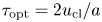 ${\tau _{\textrm{opt}}} = 2{u_{\textrm{cl}}}/a$, and the current channel width is maximal at
 ${\tau _{\textrm{opt}}}/2$ and is equal to
 $\delta ({\tau _{\textrm{opt}}}/2) = {u_{\textrm{cl}}}{\tau _{\textrm{opt}}}/4$. On completion of the conduction phase, the channel width is
 $\delta ({t_\textrm{c}}) = ({t_\textrm{c}}/{\tau _{\textrm{opt}}})(1 - {({t_\textrm{c}}/{\tau _{\textrm{opt}}})^2})l$. In the experiment considered, the current channel can first be broadened to ~3.2 cm in ~32 ns, and by the end of conduction, its narrowing to ~2 cm should be expected.
The fact that  ${\tau _{\textrm{opt}}}$ is noticeably longer than
 ${t_\textrm{c}}$ justifies using the electron drift velocity in a collisionless plasma to calculate the characteristics of current interruption. In this case, the velocity is
 ${v_{\textrm{dr}}} = 0.3\;\textrm{cm}\;\textrm{n}{\textrm{s}^{ - 1}}$ and the rate of resistance rise is
 ${\dot{R}_\textrm{s}} \approx 7.2\;\Omega \;\textrm{n}{\textrm{s}^{ - 1}}$. For an energy store with
 ${L_\textrm{g}} \approx 135\;\textrm{nH}$, the load voltage peaks at
 ${\tau _\textrm{m}} \approx 4.3\;\textrm{ns}$ and the resistance measures
 ${R_\textrm{s}}({\tau _\textrm{m}}) \approx 31\;\Omega $. Because of the energy input into the diode with
 ${R_\textrm{d}} \approx 6\;\Omega $, the switch current at the point
 ${\tau _\textrm{m}}$ is equal to
 ${I_\textrm{s}}({\tau _\textrm{m}}) = {I_0}{(1 + \alpha {\tau _\textrm{m}})^{(1 - \alpha \beta )/\alpha \beta }}{\rm exp} ( - {\tau _\textrm{m}}/\beta )$, where
 $\alpha = {\dot{R}_\textrm{s}}/{R_\textrm{d}}$ and
 $\beta = {L_\textrm{g}}/{R_\textrm{d}}$ (Loginov Reference Loginov2008), such that its value is ~107 kA. This means that the load current is more than sufficient for magnetic insulation of the gap
 $d({\tau _\textrm{m}}) \approx 1.3\;\textrm{cm}$. The current that suffices to insulate such a gap is
 ${I_{\textrm{mi}}}({\tau _\textrm{m}}) \approx (m{c^3}/2e)\gamma {r_\textrm{c}}/d({\tau _\textrm{m}}) \sim 125\;\textrm{kA}$ and its value is close to
 ${I_\textrm{s}}({\tau _\textrm{m}})$. The approximate equality
 ${I_\textrm{s}}({\tau _\textrm{m}}) \approx {I_{\textrm{mi}}}({\tau _\textrm{m}})$ is mostly because the approximation of the rise of resistance as a linear function of time is not so accurate. Nevertheless, despite the phenomenological character of
 ${I_\textrm{s}}({\tau _\textrm{m}}) \approx {I_{\textrm{mi}}}({\tau _\textrm{m}})$, the maximum switch voltage
 ${U_\textrm{s}}({\tau _\textrm{m}}) \approx 3.3\;\textrm{MV}$ correlates reasonably well with the first voltage peak of ~3 MV recorded in the experiment (Neri et al. Reference Neri, Boller, Ottinger, Weber and Young1987). Explaining the second peak with an amplitude greater than 4 MV and further peaks with lower amplitudes in the experiment needs additional argumentation.
In DECADE module experiments (Goyer et al. Reference Goyer, Kortbawi, Sincerny, Parks and Waisman1995), the conduction time was increased to ~600 ns at a bridge length of 3 cm and cathode radius of 4.44–12.7 cm. With any radius  ${r_\textrm{c}}$, the voltage
 ${U_\textrm{s}}({\tau _\textrm{m}})$ depended non-monotonically on the conduction current
 ${I_\textrm{c}}$. When
 ${I_\textrm{c}}$ became higher than a certain value, the growth of
 ${U_\textrm{s}}({\tau _\textrm{m}})$ stopped and it began to fall. For example, in a switch with
 ${r_\textrm{c}} = 12.7\;\textrm{cm}$, the voltage
 ${U_\textrm{s}}({\tau _\textrm{m}})$ ceased to increase at a current of ~600 kA rising in ~300 ns with
 $\dot{B} = 31.5\;\textrm{G}\;\textrm{n}{\textrm{s}^{ - 1}}$ and
 ${\tau _{\textrm{cl}}} \approx 2.3\;\textrm{ns}$. At this value of
 ${\tau _{\textrm{cl}}}$, the field diffuses into the plasma even at a density of 1.7 × 1014 cm−3. The plasma density calculated by formula (2.2) is
 $n \approx 1.2 \times {10^{15}}\;\textrm{c}{\textrm{m}^{ - 3}}$. The validity of formula (2.2), suggesting that the field penetrates the plasma with a velocity
 ${u_\textrm{d}}$, is also confirmed by the fact that for carbon plasma, the optimum time
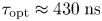 ${\tau _{\textrm{opt}}} \approx 430\;\textrm{ns}$ is longer than the conduction time.
When the current is cut off in a plasma of density  $n \approx 1.2 \times {10^{15}}\;\textrm{c}{\textrm{m}^{ - 3}}$, the rate of resistance rise is
 ${\dot{R}_\textrm{s}} = 60\;\mathrm{m\Omega }\;\textrm{n}{\textrm{s}^{ - 1}}$. In this case,
 ${L_\textrm{g}} = 500\;\textrm{nH}$ (which is determined by the ratio of the output generator voltage of ~1 MV (Goyer et al. Reference Goyer, Kortbawi, Childers, Sincerny, Weber, Ottinger, Commisso, Thompson and Babineau1997) to the rate of rise of the switch current of ~2 kA ns−1),
 ${\tau _\textrm{m}} \approx 91\;\textrm{ns}$ and the voltage amplitude applied to the diode with
 ${R_\textrm{d}} \approx 7\;\Omega $ is
 ${U_\textrm{s}}({\tau _\textrm{m}}) \approx 1.3\;\textrm{MV}$ corresponding to its experimental value. The current
 ${I_\textrm{s}}({\tau _\textrm{m}}) \approx 240\;\textrm{kA}$ is of the order of
 ${I_{\textrm{mi}}}({\tau _\textrm{m}}) \approx 340\;\textrm{kA}$; that is, ~360 kA switched to the load provides magnetic insulation of the gap formed.
In the switch with  ${r_\textrm{c}} = 4.44\;\textrm{cm}$, the current reached ~1 MA in ~500 ns. For
 $\dot{B} \approx 90\;\textrm{G}\;\textrm{n}{\textrm{s}^{ - 1}}$, the optimum time is
 ${\tau _{\textrm{opt}}} \approx 260\;\textrm{ns}$, which is half the conduction time and for which the magnetic piston approximation is seemingly useful. However, in this case, the plasma density should be ~3.7 × 1016 cm−3. Then,
 ${\dot{R}_\textrm{s}} \approx 27\;\textrm{m}\Omega \;\textrm{ns}^{-1}$ and
 ${\tau _\textrm{m}} \approx 140\;\textrm{ns}$, and even with neglect of the density increase in the current channel,
 ${U_\textrm{s}}({\tau _\textrm{m}})$ reaches only ~1.7 MV against its experimental value of ~2.8 MV. If, despite
 ${t_\textrm{c}} \gt {\tau _{\textrm{opt}}}$, we do admit the field velocity
 ${u_\textrm{d}}$, we can obtain a better agreement with the experiment and with the growth of
 ${U_\textrm{s}}({\tau _\textrm{m}})$ up to a conduction time of ~500 ns. If so, we have
 $n \approx {10^{16}}\;\textrm{c}{\textrm{m}^{ - 3}}$,
 ${\dot{R}_\textrm{s}} \approx 100\;\textrm{m}\Omega \;\textrm{n}{\textrm{s}^{ - 1}}$,
 ${\tau _\textrm{m}} \approx 70\;\textrm{ns}$ and
 ${U_\textrm{s}}({\tau _\textrm{m}}) \approx 2.6\;\textrm{MV}$ close to its experimental value. At the instant the voltage peaks,
 ${I_\textrm{s}}({\tau _\textrm{m}}) \approx 360\;\textrm{kA}$ and
 ${I_{\textrm{mi}}}({\tau _\textrm{m}}) \approx 440\;\textrm{kA}$, which is ~0.7 of the switched diode current.
Without going further with examples, it can be said that the incredible simplicity of the proposed relations makes them suitable for re-analysing any other experiment. What is noteworthy is that the magnetic field velocity  ${u_\textrm{d}}$ in some cases can be possible up to a conduction time of ~500 ns.
Of interest is, however, what limiting value of  ${U_\textrm{s}}({\tau _\textrm{m}})$ is hypothetically possible at
 ${t_\textrm{c}} = {\tau _{\textrm{opt}}}$. This condition, given the conduction time
 ${t_\textrm{c}}$ and rate of current rise
 $\dot{I}$, determines the cathode radius
 ${r_{\textrm{opt}}} = (2/3{\rm \pi} )(Zm/{m_\textrm{i}})e\dot{I}t_\textrm{c}^2/m{c^2}$. The corollary
 $n{l^2} = 3{\rm \pi} {m_\textrm{i}}{c^2}/16Z{e^2}$, which automatically follows from formulae (2.2) and (2.3), gives a maximum optimum bridge length
 ${l_{\textrm{opt}}}$ at a minimum attainable plasma density. For the field velocity
 ${u_\textrm{d}}$, the minimum attainable plasma density is determined by the condition
 ${\tau _{\textrm{cl}}} = {\tau _{\textrm{ei}}}$ and is given by
 ${n_{\textrm{opt}}} = {{\rm \pi} ^{1/2}}{({m_\textrm{i}}/Zm)^{1/2}}m\sigma /{e^2}{t_\textrm{c}}$. These parameters determine the possibility of reaching the limiting voltage without regard for the plasma density build-up in the current channel due to plasma aggregation by a magnetic piston. For inductance-to-inductance energy switching,
 ${U_{\textrm{opt}}} = \lambda L_\textrm{t}^{1/2}{({m_\textrm{i}}/Zm)^{5/8}}{({m^2}/{e^2}\sigma )^{1/4}}{\dot{I}^{3/4}}/I_\textrm{c}^{1/4}$ with a numerical coefficient
 $\lambda = {3^{3/4}}{{\rm \pi} ^{1/8}}/{e^{1/2}} \approx 1.6$, where e is Napier's number. In another form,
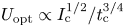 ${U_{\textrm{opt}}} \propto I_\textrm{c}^{1/2}/t_\textrm{c}^{3/4}$ with
 ${U_{\textrm{opt}}} \propto I_\textrm{c}^{1/2}$ belonging to the ascending part of the voltage scaling. At the same time, it is clear that increasing the rise time of the conduction current for no change in its value decreases the peak voltage in the phase of current cutoff:
 ${U_{\textrm{opt}}} \propto t_\textrm{c}^{ - 3/4}$. Thus, increasing the primary store energy and the conduction time
 ${t_\textrm{c}}$ will decrease the switch power. This negative tendency is determined by the mechanism of magnetic field transport through the switch plasma.
In conclusion, let us look at which parameters are optimal for maximum possible voltages in the switches considered above. For the GAMBLE II switch, these are  ${n_{\textrm{opt}}} \approx 1.5 \times {10^{15}}\;\textrm{c}{\textrm{m}^{ - 3}}$,
 ${r_{\textrm{opt}}} \approx 1.3\;\textrm{cm}$ and
 ${l_{\textrm{opt}}} \approx 4\;\textrm{cm}$ such that
 ${\dot{R}_\textrm{s}} \approx 4.8\;\Omega \;\textrm{n}{\textrm{s}^{ - 1}}$,
 ${\tau _\textrm{m}} \approx 5.3\;\textrm{ns}$ and
 ${U_{\textrm{opt}}}({\tau _\textrm{m}}) \approx 3.2\;\textrm{MV}$ at a load
 ${R_\textrm{d}} \approx 6\;\Omega $. For the DECADE switch with
 ${I_\textrm{c}} = 0.6\;\textrm{MA}$, the optimum parameters are
 ${n_{\textrm{opt}}} \approx 2.4 \times {10^{14}}\;\textrm{c}{\textrm{m}^{ - 3}}$,
 ${r_{\textrm{opt}}} \approx 6\;\textrm{cm}$ and
 ${l_{\textrm{opt}}} \approx 10\;\textrm{cm}$ such that
 ${\dot{R}_\textrm{s}} \approx 0.4\;\Omega \;\textrm{n}{\textrm{s}^{ - 1}}$,
 ${\tau _\textrm{m}} \approx 35\;\textrm{ns}$ and
 ${U_{\textrm{opt}}}({\tau _\textrm{m}}) \approx 2.3\;\textrm{MV}$ at a load
 ${R_\textrm{d}} \approx 7\;\Omega $. With
 ${I_\textrm{c}} = 1\;\textrm{MA}$, we have
 ${n_{\textrm{opt}}} = 1.5 \times {10^{14}}\;\textrm{c}{\textrm{m}^{ - 3}}$,
 ${r_{\textrm{opt}}} \approx 17\;\textrm{cm}$ and
 ${l_{\textrm{opt}}} \approx 13\;\textrm{cm}$ such that
 ${\dot{R}_\textrm{s}} \approx 0.1\;\Omega \;\textrm{n}{\textrm{s}^{ - 1}}$,
 ${\tau _\textrm{m}} \approx 67\;\textrm{ns}$ and
 ${U_{\textrm{opt}}}({\tau _\textrm{m}}) \approx 2.7\;\textrm{MV}$ at the same load. From comparison of these data and experimental data it is seen that decreasing the plasma density does not guarantee a higher switch efficiency. Actually,
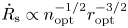 ${\dot{R}_\textrm{s}} \propto n_{\textrm{opt}}^{ - 1/2}r_{\textrm{opt}}^{ - 3/2}$, and to obtain a bridge with a low
 ${n_{\textrm{opt}}}$ value, the value of
 ${r_{\textrm{opt}}}$ should be increased to provide the desired current. The criterion of increasing
 ${U_\textrm{s}}({\tau _\textrm{m}})$ with
 ${I_\textrm{c}}$ is the condition
 ${t_\textrm{c}} \lt {\tau _{\textrm{opt}}}$ which depends on the rate of magnetic field rise and determines the cathode radius necessary at a given current rise time. If this condition holds, the magnetic piston coordinate within a pulse is smaller than the coordinate of the magnetic field front penetrating the plasma with a velocity
 ${u_{\textrm{cl}}}$ or
 ${u_\textrm{d}}$. This impedes the increase in the plasma density of the current channel as the energy is switched to the load.
5. Conclusion
The proposed approach allows a consistent interpretation of the plasma dynamics in switches with any conduction time. It provides practically useful relations for the conduction current and for the voltage on its cutoff. From the performed analysis also follow some conclusions valuable not only for switches but for other high-current plasma dynamic systems as well. The most significant and interesting among them are formulated below.
The use of POSs for power amplification at a load is expedient only with a plasma density at which the collisionless ion skin layer is no greater than  $2/\sqrt 3 {\rm \pi} $ of the bridge length; otherwise, the plasma dynamics starts to be dominated by aggregation under magnetic field pressure with the result that the switch voltage begins to fall as the conduction current gets higher.
For any mechanism of magnetic field penetration, a polarization electric field is needed to provide radial flows of magnetized electrons and plasma acceleration. This field, also known as the Hall field, cannot be delegated to electron magnetohydrodynamics for realizing quite exotic electron flows against immobile ions (Kingsep, Chukbar & Yankov Reference Kingsep, Chukbar and Yankov1990; Fruchtman Reference Fruchtman2017).
The drift of magnetized electrons in the volume of plasma means that the current channel conductivity is suppressed by two to three orders of magnitude compared to the Spitzer value. The fact of anomalously high current channel resistivity was noted even in the first experiments with nanosecond switches (Weber et al. Reference Weber, Commisso, Meger, Neri, Oliphant and Ottinger1984) but it was not given an appropriate theoretical explanation. Meanwhile, the suppression of conductivity is a natural and logical consequence of electron magnetization in current channels. This conclusion holds as well for other high-current plasma dynamic systems.
Acknowledgements
The work was performed under state budget. The author is grateful to the reviewers of the manuscript for valuable and useful comments.
Editor Troy Carter thanks the referees for their advice in evaluating this article.
Declaration of interests
The author reports no conflict of interest.