I. INTRODUCTION
Chirp waveform is one of the most used signals in radars due to its high Doppler tolerance [Reference Curtis Schleher1], but chirp radars are vulnerable to active jamming, which is the process of transmitting interfering signals toward the victim radar with the objective of degrading its ability to detect targets or to make it obtain wrong information about them. According to the jamming topology, we can distinguish between self-protection and stand-off jammers. In self-protection topology, the jammer is carried by the same vehicle or airplane to be protected from detection by a hostile radar. While, in stand-off jammers, the target is protected by a jammer carried by other friendly platform (vehicle or airplane) or located at some distance far from the hostile radar [Reference Stimson, Griffiths, Baker and Adamy2]. Another difference between these two jamming modes is the gain of the radar's transmit antenna in the direction of the jamming system, which is the side lobe antenna gain for the stand-off jamming and the main lobe antenna gain for the self-protection jamming, respectively [Reference Stimson, Griffiths, Baker and Adamy2, Reference Shi, Wang, Sellathurai and Zhou3].
The active jammers can be classified as cover jammers and deceptive jammers. Cover jammers mask the friendly targets by continuous transmission of high-power noise signal concentrated around the radar frequency, but deceptive jammers transmit modified versions of the radar signal, which distorts the matched filter output and generates false targets. An important parameter in these jamming systems is the jammer-to-signal ratio (JSR), which is often greater than unity [Reference Stimson, Griffiths, Baker and Adamy2].
Since the signal of deceptive jammer looks like the reflected signal from the target, it benefits from the pulse compression processing gain of the radar. Therefore, the jammer does not need high-power transmission in order to be effective. In contrast, when countering radars by transmitting noise signal, the jamming signal does not benefit from the gain of the matched filter. Therefore, the jammer needs high-power transmission in order to disable the radar's capability for detecting the true target. However, high jamming power could lead to the hostile anti-radiation missile attack [Reference Shi, Wang, Sellathurai and Zhou3].
Since digital radio frequency memory (DRFM) jammers retransmit the jamming pulses behind the true target echo, they can be recognized by radar systems easily [Reference De Martino4]. Therefore, different repeater jammers are proposed in literatures for avoiding the limitations of DRFM jammer; for instance, frequency-shifting jammer, interrupted sampling repeater jammer (ISRJ), and the spectrum-dividing jammer [Reference Yong, Zhang and Yang5–Reference Pan, Wang, Feng, Fu and Wang7].
Frequency-shifting jammers benefit from the well-known range-Doppler coupling property of chirp waveform, where a copy of the radar signal shifted in frequency can be transmitted as an echo to the radar to confuse it, because the jammer signal in this case looks like the radar return [Reference Yong, Zhang and Yang5].
ISRJ is an effective method to jam chirp radars. ISRJ is based on sampling and storing segments of the radar signal and retransmitting them toward the victim radar. By this way, the ISRJ generates many false targets at the output of radar-matched filter [Reference Wang, Liu, Zhang, Fu, Liu and Xie6].
The spectrum-dividing jammer divides a received radar signal into several equal parts to form a whole jamming signal before being retransmitted back to the radar in a different order. By this way, many false targets are generated at the output of radar-matched filter [Reference Pan, Wang, Feng, Fu and Wang7].
This paper presents a review of deceptive repeater jammers against chirp radar, including frequency-shifting jammer, ISRJ, and spectrum-dividing jammer in Sections II, III, and IV respectively, where a basic theoretical analysis and Matlab® simulation results of jamming systems are described. Finally, the comparison between different jamming types, and the practical guidance to the target detection in the jamming environment are given in Section V.
II. FREQUENCY-SHIFTING JAMMING
Frequency-shifting jammer can generate false targets at the output of radar-matched filter by instantly shifting the frequency of radar signal. The jamming retransmission may take different modes, such as single-false target jamming, multiple-false targets jamming, and multiple-cover jamming [Reference Yong, Zhang and Yang5].
The main advantage of frequency-shifting jamming is its ability to generate many false targets before and after the true target. However, the amplitudes of these false targets are lower than the amplitude of the true one, first because of the frequency mismatch between the jamming signals and the matched filter, and second because the jamming signals could be only parts of the radar pulse. Therefore, the jammer has to increase its power in order to compensate for these losses. Another disadvantage of this jammer is the need of a high isolation of two receive–transmit antennas, which might be difficult to implement.
A) Single-false target jamming
Let x(t) be the complex representation of the transmitted radar chirp [Reference Yong, Zhang and Yang5]:
 $$x(t) = \displaystyle{1 \over {\sqrt T}} rect\left( {\displaystyle{t \over T}} \right)e^{j\mu \pi t^2}, \quad \left \vert t \right \vert \lt \displaystyle{T \over 2},$$
where T is the chirp duration, μ = B/T is the frequency modulation slope, and B is the sweep bandwidth. Then, the complex representation of the jamming signal is given by [Reference Yong, Zhang and Yang5]:
 $$x_J (t) = x(t)e^{j2\pi f_J t} = {\rm \;} e^{j2\pi f_J t + j\pi \mu t^2}, \quad \left \vert t \right \vert \lt \displaystyle{T \over 2},$$
where f J is the frequency shift of the jammer. When f J ≪ B, then the output of the matched filter is given by [Reference Yong, Zhang and Yang5]:
 $$\eqalign{s_J (t) & = \sqrt {BT} \left( {1 - \displaystyle{{f_J} \over B}} \right) \cdot sinc\left[ {\pi \left( {B - f_J} \right)\left( {t - t_0 + \displaystyle{{f_J} \over \mu}} \right)} \right] \cr & \cdot e^{j\pi f_J (t - t_0 )},}$$
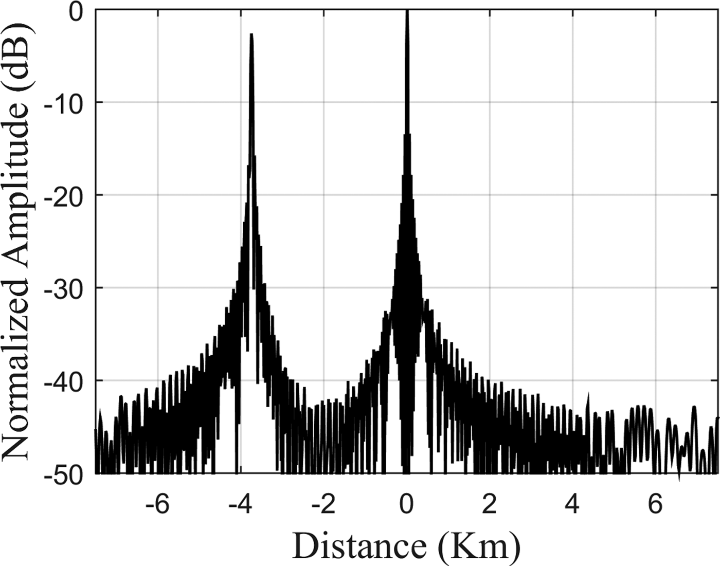
where t 0 = 2R/c is the time delay of the true target echo, c is the speed of light, and R is the true target range. Equation (3) shows that the amplitude of the false target is less than the amplitude of the true target by a factor of (1 − f J /B), also it shows that the false target lags behind the true target when f J <0 and leads it when f J >0 by a distance of d = cf J /2μ.
Figure 1 shows the simulation result of single-false target jamming when B = 4 MHz, T = 100 µs, f j = 1 MHz, and JSR = 0 dB. In this case, d = 3.750 km.
The simulation result of single-false target jamming.

B) Multiple-false targets jamming
In order to make it difficult for the radar to recognize the true target, several false targets could be generated simultaneously at the output of the matched filter. The jammer divides radar pulse into N parts, and then modulates them by different frequencies. The first part is modulated by f J0, and the modulated frequency of each part is [Reference Yong, Zhang and Yang5]:
 $$f_{Jn} = f_{J0} + \left( {n - 1} \right)\Delta f_J, \quad \; n = 1,2,3,\; \ldots, N,$$
where Δf J is the difference between the modulation frequencies of every two adjacent parts. The jamming signal is given by [Reference Yong, Zhang and Yang5]:
 $$\eqalign{x_{Jn} (t) = e^{j2\pi f_{Jn} t + j\pi \mu t^2}, \; \quad t\; \in \left( { - \displaystyle{T \over 2} + \displaystyle{{n - 1} \over N}T, - \displaystyle{T \over 2} + \displaystyle{n \over N}T} \right).}$$
In this case, all the false targets have the same amplitude, which is less than the amplitude of the true target by a factor of 1/N, and the number of false target equals [Reference Yong, Zhang and Yang5]:
 $$N_{ft} = \displaystyle{{B - f_{J0}} \over {\mu. \Delta T + \Delta f_J}}, $$
where ΔT = T/N. When f Jn ∈ [0, (N − n/N)B], the matched filter output is given by [Reference Yong, Zhang and Yang5]:
 $$\eqalign{S_{Jn} (t) & = \displaystyle{{\sqrt {BT}} \over N}\; sinc\left[ {\displaystyle{{\pi B} \over N}\left( {t - t_0 + \displaystyle{{f_{Jn}} \over \mu}} \right)} \right] \cr & \cdot e^{j[2\pi (t - t_0 + (f_{Jn} /\mu ))(f_{Jn} + (2n - N - 1/2N)B) - \pi f_{Jn}^2 /\mu ]\; }.}$$
The relative distance between each false target and the true one is d n = cf Jn /2μ.
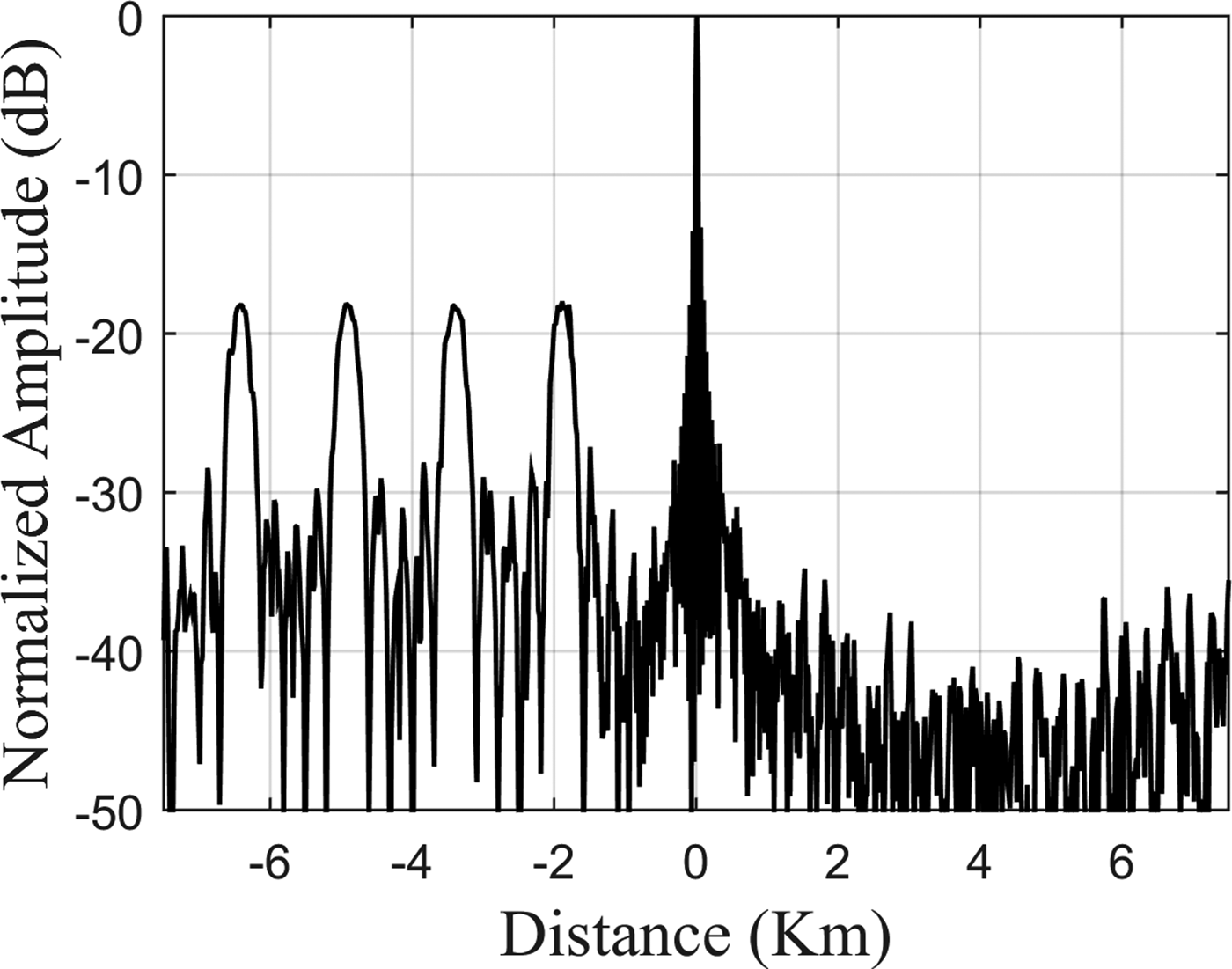
Figure 2 shows the simulation result of multiple-false targets jamming when B = 4 MHz, T = 100 µs, N = 8, f J0 = 0.5 MHz, Δf J = 0.4 MHz, and JSR = 0 dB. In this case, N ft = 4, according to equation (6), and the corresponding forward-shifting distance equals 1.875, 3.375, 4.875, 6.375 km, respectively.
The simulation result of multiple-false targets jamming.

C) Multiple-cover jamming
The multiple-cover jamming is better than the single-false target and multiple-false targets jamming [Reference Yong, Zhang and Yang5], because it has an effect of blanket jamming. In this case, the jammer divides radar pulse into N parts at first, and then frequency modulate each part linearly. This gives false targets each of which covers some range in the frequency domain that is more efficient in jamming.
The jamming signal is given by [Reference Yong, Zhang and Yang5]:
 $$\eqalign{x_{Jn} (t) = e^{j2\pi f_{Jn} t + j\pi (\mu + \mu _J )t^2}, \; \quad t \in \left( { - \displaystyle{T \over 2} + \displaystyle{{n - 1} \over N}T, - \displaystyle{T \over 2} + \displaystyle{n \over N}T} \right),}$$
where μ J is the frequency modulation slope of the jamming signal.
The modulated frequency on each part is:
 $$f_{Jn} = f_{J0} + \left( {n - 1} \right)\Delta f_J, \; n = 1,\; 2,\; 3,\; \ldots, N,$$
where f J0 is the initial modulated frequency of the first part of jamming signal.
The number of the cover jamming is given by [Reference Yong, Zhang and Yang5]:
 $$N_{ft} = \displaystyle{{B - f_{J0}} \over {(\mu + \mu _J ) \cdot \Delta T + \Delta f_J}}. $$
The nearest distance of each jamming covered is given by [Reference Yong, Zhang and Yang5]:
 $$\displaystyle{{c(f_{Jnc} - (\mu _J T/2) - (\Delta f_J /2))} \over {2\mu}}, $$
where f Jnc is the center frequency of each jamming signal.
The distance range each jamming covered is given by [Reference Yong, Zhang and Yang5]:
 $$\displaystyle{c \over 2} \cdot \displaystyle{{\mu _J ((B + B_J /N) + \Delta f)} \over {\mu (\mu + \mu _J )}}.$$
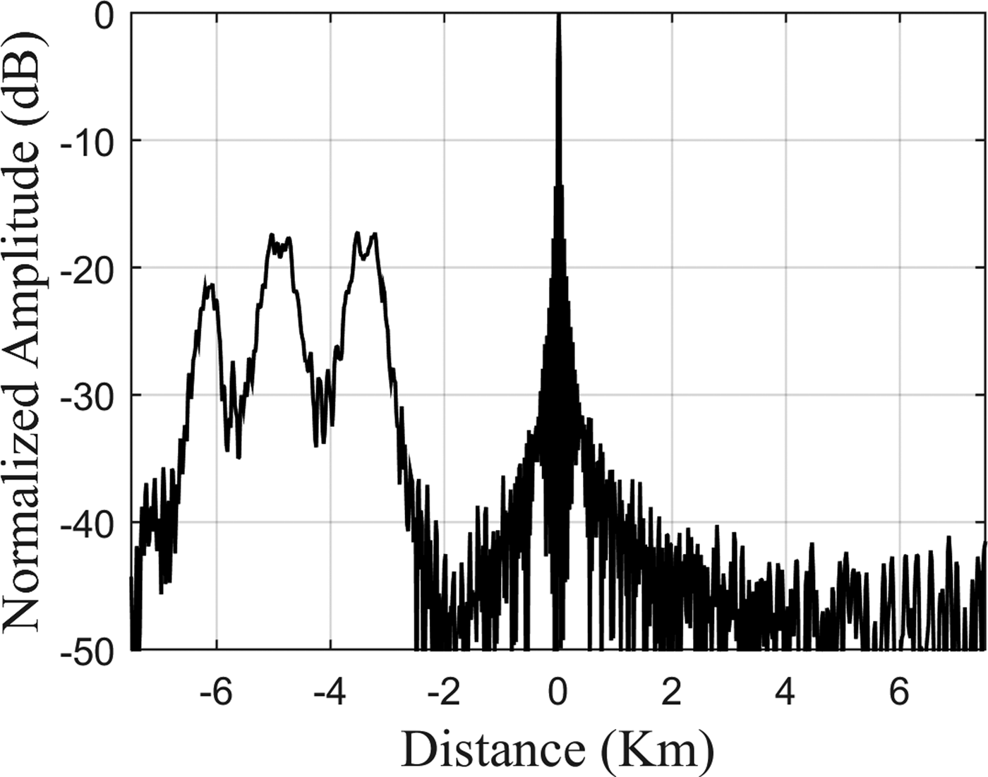
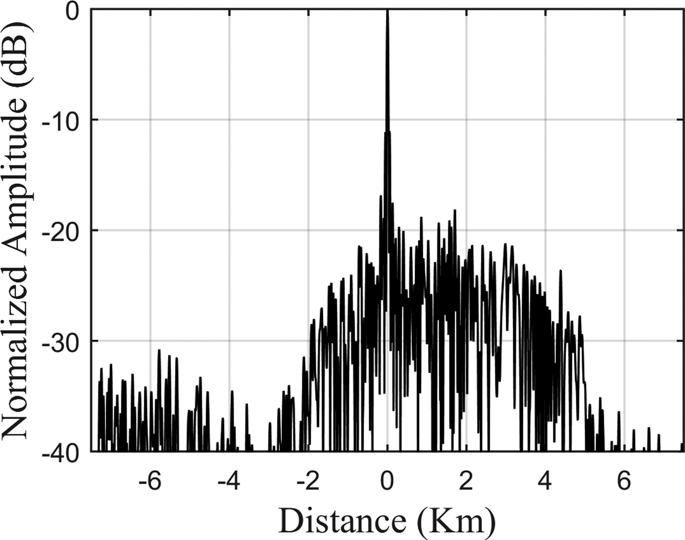
Figure 3 shows the simulation result of multiple-cover jamming when B = 4 MHz, T = 100 µs, N = 4, f J0 = 0.8 MHz, Δf J = 0.2 MHz, μ J = 4 MHz/ms, and JSR = 0 dB. In this case, N ft = 3, according to equation (10), the nearest cover distance of the jamming is 3 km, and each jamming covers 443 m, according to equations (11) and (12), respectively.
The simulation result of multiple-cover jamming.

III. INTERRUPTED SAMPLING REPEATER JAMMER
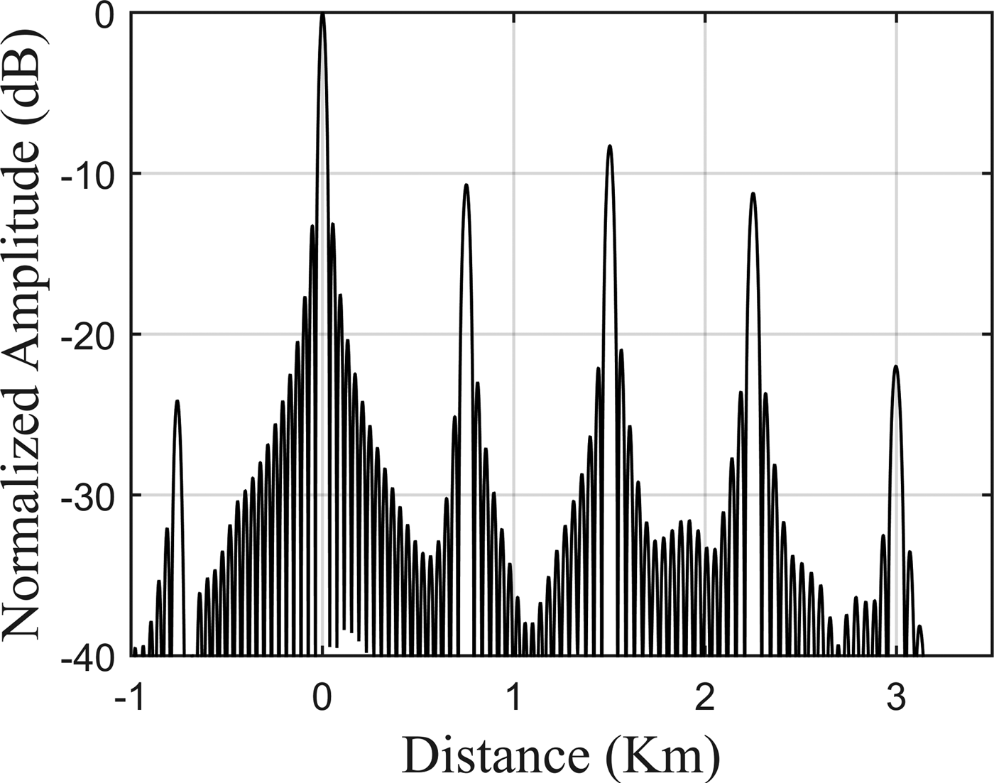
It is an effective method to deceive chirp radars. This method is based on sampling and storing segments of the radar signal and retransmitting them toward the victim radar. By this way, the ISRJ generates main false target that always lags behind the true target by jammer's delay τ d , and several other false targets that are located symmetrically around the main false target, at the output of radar-matched filter [Reference Wang, Liu, Zhang, Fu, Liu and Xie6].
A) The advantages and shortcomings of ISRJ
ISRJ has some advantages such as [Reference Wang, Liu, Zhang, Fu, Liu and Xie6, Reference Li, Su, Gu, Ma and Chen8]:
-
• A jammer used one receive and transmit time-sharing antenna, so there is no need for high isolation of two receive–transmit antennas.
-
• A receive and transmit time-sharing antenna can be carried by a missile, because it has easier implementation than the two receive–transmit antennas.
-
• The spatial distribution of the false targets can be adjusted by controlling the repeated time delay of jammer. Therefore, there is no need to do complex frequency modulation.
ISRJ has two main shortcomings [Reference Wang, Liu, Zhang, Fu, Liu and Xie6, Reference Li, Su, Gu, Ma and Chen8]:
-
• Power amplification is required due to interrupted sampling.
-
• The effective false targets of ISRJ lag behind the true target. Therefore, they could be recognized by radar.
B) The principle of ISRJ
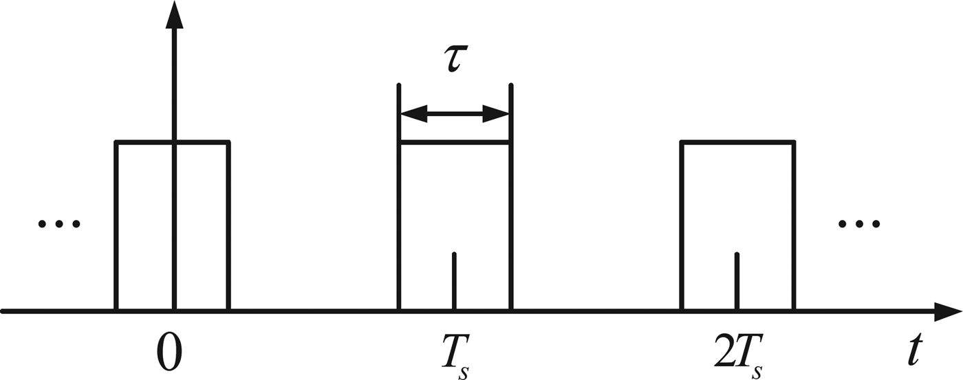
The sampling function p(t) is a rectangular pulse train with pulse duration τ and pulse repeat interval T s = 1/f s , as shown in Fig. 4. The jammer receives the radar chirp and samples it in the interrupted mode, where a single antenna is used for receive and transmit alternately [Reference Wang, Liu, Zhang, Fu, Liu and Xie6].
Interrupted sampling function.

The output of the matched filter is given by [Reference Wang, Liu, Zhang, Fu, Liu and Xie6]:
 $$y(t) = \mathop \sum \limits_{n = - \infty} ^\infty a_n u_n (t),$$
where
 $$a_n = \tau f_s \,sinc\left( {\pi nf_s \tau} \right),$$
and u n (t) is given by [Reference Wang, Liu, Zhang, Fu, Liu and Xie6]:
 $$u_n (t) = sinc\left[ {\pi \left( {nf_s + \mu t} \right)\left( {T - \left \vert t \right \vert} \right)} \right]\left( {1 - \displaystyle{{\left \vert t \right \vert} \over T}} \right)e^{j\pi nf_s t}. $$
On the basis of equations (13) and (15), it is clear that matched filter output consists of many false targets {u n (t)}, each one has a frequency shift nf s and a scale factor a n . With increasing values of n, the amplitudes of false targets decrease rapidly according to the sinc function. In practice, this ISRJ technique usually generates 3–5 effective false targets [Reference Wang, Liu, Zhang, Fu, Liu and Xie6].
Figure 5 shows the simulation result of ISRJ when B = 4 MHz, T = 100 µs, τ = 2 µs, τ d = 10 µs, f s = 200 KHz, and JSR = 0 dB. In this case, the main false target lags behind the true target by 1.5 km, and the other false targets are located symmetrically around it.
The simulation result of ISRJ.

C) Improved ISRJ
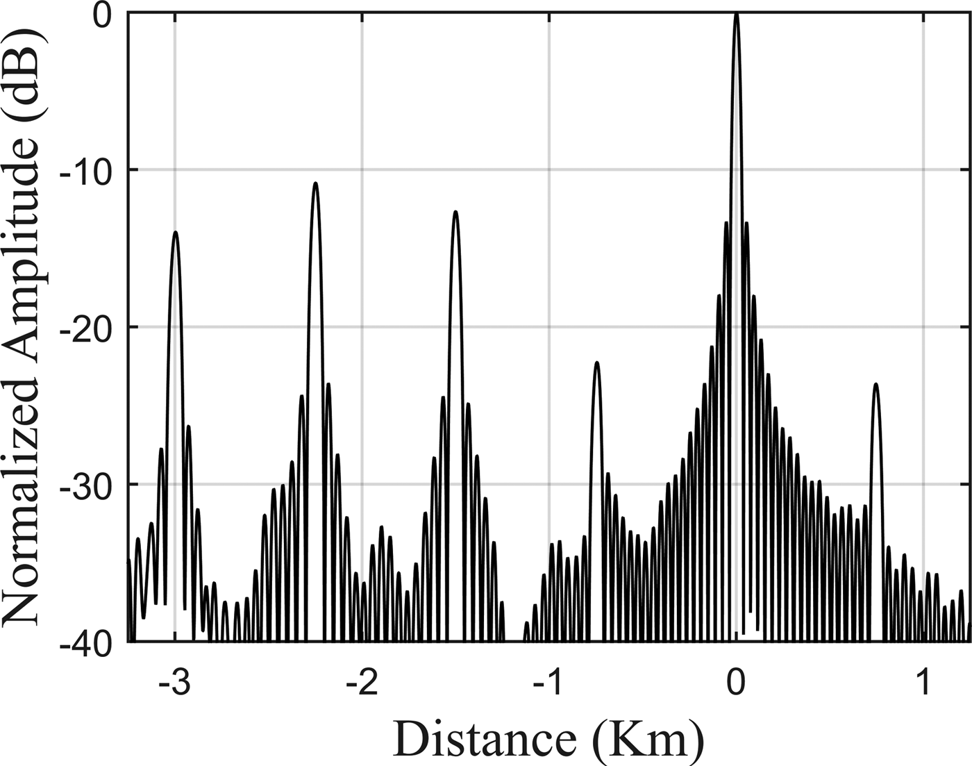
Some researchers proposed modified versions of ISRJ to make it more effective as shown in the following examples [Reference Li, Su, Gu, Ma and Chen8–Reference Tai, Yuan and Pan10]:
1) GENERATION A TRAIN OF FALSE TARGETS THAT PRECEDE THE TRUE ONE
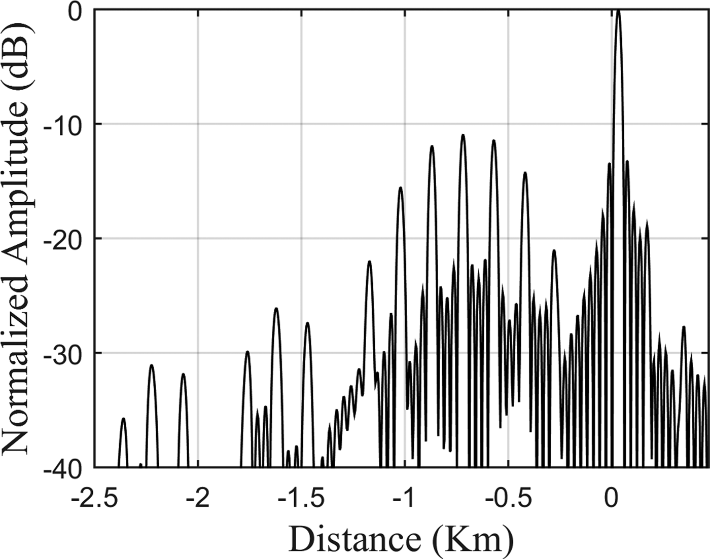
The effective false targets of ISRJ lag behind the true target because of the jammer's delay τ d ; they could be recognized by radar easily. Therefore, a frequency shift or DRFM can be applied to put them before the true target.
DRFM is applied as follows [Reference Li, Su, Gu, Ma and Chen8]:
-
• The radar signal is received and stored to digital memory.
-
• The sampled signal is multiplied with its delay signal that can obtain false targets that lead the true one.
-
• The amplitude can be amplified before retransmitting to overcome the amplitude decrease.
The signal processing of improved ISRJ with DRFM causes a frequency shift that moves the position of false targets forward [Reference Li, Su, Gu, Ma and Chen8]. Several false targets are generated after matched filter as shown in equation (16).
 $$\eqalign{& {y_j (t) = \tau f_s \left( {1 - \displaystyle{{\left \vert t \right \vert} \over T}} \right)\mathop \sum \limits_{n = - \infty} ^{ + \infty}sinc\left( {\pi f_s \tau} \right)} \cr & . \;{sinc\{ {( {\mu t + \Delta f + nf_s} )} ( {T - \vert t \vert})}\} \cdot e^{\{ {j\pi [( {\Delta f + nf_s} )t - nf_s (\tau _0 + \tau _d )} \}},} $$
where τ 0 is the DRFM delay, and Δf = μ(τ − 2τ 0) is the frequency shifting that is caused by signal processing of improved ISRJ.
Figure 6 shows the simulation result of ISRJ with frequency shift when B = 4 MHz, T = 100 µs, τ = 2 µs, τ d = 10 µs, τ = 2 µs, f s = 200 KHz, f J = 1 MHz, and JSR = 0 dB. Figure 7 shows the simulation result of ISRJ with DRFM when f s = 250 KHz, τ d = 10 µs, τ 0 = 2.5 µs, and JSR = 0 dB. In both previous figures, the effective false targets of ISRJ lead the true target.
The simulation result of ISRJ with frequency shift.

The simulation result of ISRJ with DRFM.

2) ACTIVE ECHO CANCELLATION
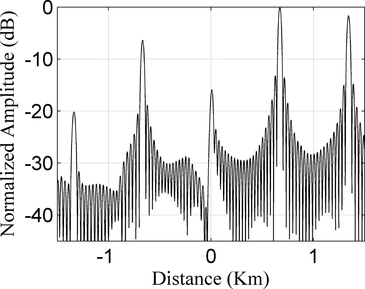
When τ d = f s /μ, then the first false target adjacent to and preceding the main false target (−1st false target) will coincide with the true target, a property proposed in [Reference Feng, Xu, Wang and Yang9] for partial echo cancellation if the false target phase is exactly opposing the true target phase and the amplitudes of these two targets are equal.
The phase of the radar target echo consists of two components: the propagation phase and the signature of the radar target itself. In self-protection jamming, the target and jammer echoes travel the same distance to the radar, and therefore the propagation phase difference is zero. On the other hand, it is assumed, for simplicity, that the target cross-section amplitude equals 1 and the phase equals 0 [Reference Feng, Xu, Wang and Yang9]. The −1st false target will cancel the target echo when τ d , f s , and the jammer gain A j satisfy [Reference Feng, Xu, Wang and Yang9]:
 $$\tau _d = f_s /\mu $$
to bring the −1st false target to the location of the true target,
 $${\rm \; \; \;} f_s = \sqrt \mu $$
to make the phase of the −1st false target opposite to the phase of the true target, and
 $$A_j = \displaystyle{1 \over {a_{ - 1}}} = \displaystyle{1 \over {\tau f_s \,sinc( - \pi f_s \tau )}}$$
for the amplitudes of the two echoes to be equal.
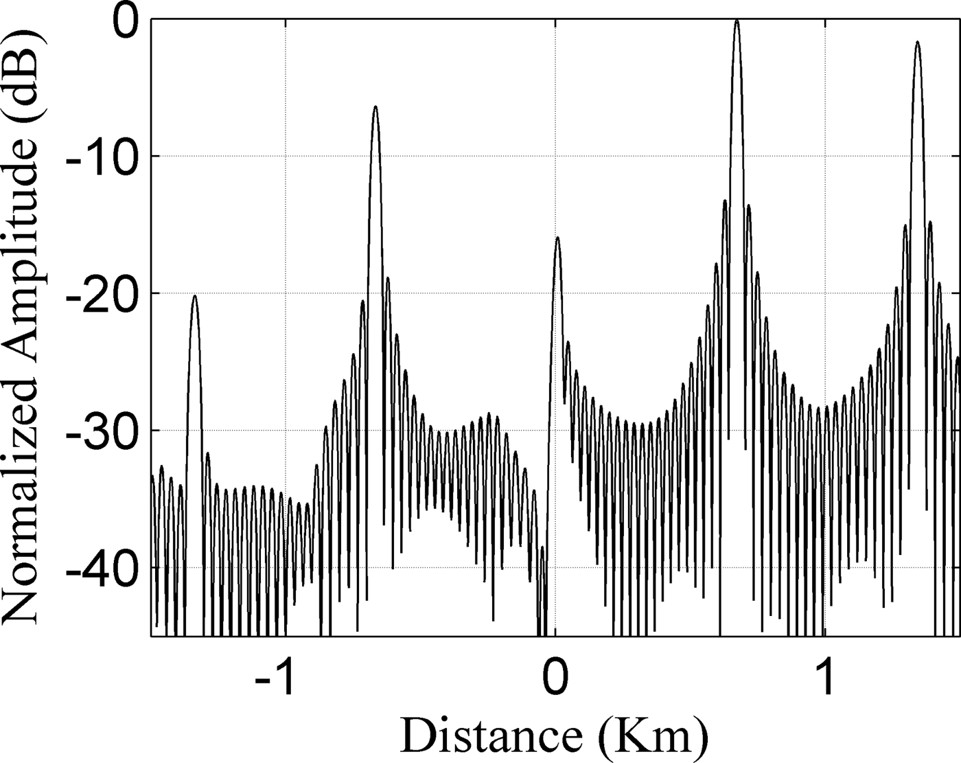
Figure 8 shows the simulation results of active echo cancellation jamming when T = 100 µs, B = 5 MHz, and τ = 1.34 µs, then f s = 224 KHz, τ d = 4.47 µs, and A j = 3.8, according to equations (17), (18), and (19), respectively. In this case, the true target is suppressed in front of the main false target to about −16 dB, because of the coherent cancellation with −1st false target.
The simulation results of active echo cancellation.
3) BLANKET JAMMING
The blanket jamming effect will be formed when modulating radar echo using pseudo-random noise sequence (PRN). A different covering distances and jamming effects will be achieved by flexible controlling the parameters of ISRJ and PRN [Reference Tai, Yuan and Pan10].
PRN is commonly generated using linear feedback shift register (LFSR). The maximum length of the sequence created by n bit shift register equals to P = 2 n − 1. The power spectral density of pseudo-random sequence that has a chip width T c and a period T is given by [Reference Tai, Yuan and Pan10]:
 $$G(f) = \displaystyle{{P + 1} \over {P^2}} sinc^2 (\pi fT_c )\mathop \sum \limits_{\matrix{ {l = - \infty} \cr {l \ne 0} \cr}} ^{l = \infty} \delta \left( {f - \displaystyle{l \over {PT_c}}} \right) + \displaystyle{1 \over {P^2}} \delta \left( f \right).$$
The shape of this power spectral density follows sinc 2 function. Furthermore, its width controlled by T c ; the shorter T c , the wider frequency spreading but its amplitude level will be down. In fact, binary phase modulation of the chirp waveform, using PRN, is equivalent to shifting chirp waveform simultaneously by a series of frequencies.
The ISRJ modulates the phases of sampled radar signal according to the values of PRN, and then it sends the jamming signal to victim radar. This method will form a large amount of noise around the pulse compression output of target echo, because the spectrum of radar signal is expanded by modulating it by PRN. However, in this case, a n ≪ 1. Therefore, the jammer has to increase JSR to a high degree in order to disable the radar's capability for detecting the true target [Reference Tai, Yuan and Pan10].
Figure 9 shows the simulation results of the blanket jamming when T = 100 µs, B = 5 MHz, and P = 127, T c = 800 ns, f s = 200 KHz, and JSR = 0 dB. In this case, more JSR is required to cover the true target by noise jamming.
The simulation results of the blanket jamming.

IV. THE SPECTRUM-DIVIDING JAMMER
The spectrum-dividing jammer divides a received radar signal into several equal parts to form a whole jamming signal before being retransmitted back to the radar in a different order. A train of false targets will be achieved at the output of radar-matched filter. The spectrum changed in the jamming signal contrast to the original radar signal will induce different time delay due to the group delay [Reference Pan, Wang, Feng, Fu and Wang7]. Figure 10 shows the schematic diagram of this jammer, the chirp is divided into N equal pulses in frequency spectrum and arranged in a different order to form the jamming signal.
The schematic diagram of the spectrum-divided repeat jamming. (a) Radar signal; (b) jamming signal.

The ith pulse in the radar signal (called signal order) is retransmitted as kth part in the jamming signal (called jamming order or retransmitted order), and the k i th jamming pulse is derived [Reference Pan, Wang, Feng, Fu and Wang7]:
 $$p_{k_i} (t) = rect\left[ {\displaystyle{{t - \left( { - (T/2) + (k/N)T + (T/2N)} \right)} \over {T/N}}} \right]e^{j\pi \mu [t - (k - i)T/N]^2}, $$
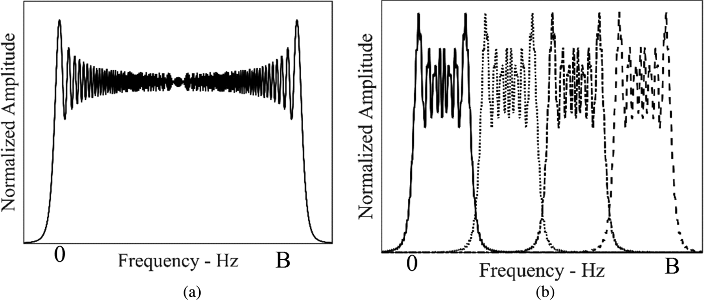
where k, i = 0, 1, …, N − 1. From equation (21), it can be seen that the retransmitted jamming pulse is a chirp signal with T/N in duration and B/N in bandwidth [Reference Pan, Wang, Feng, Fu and Wang7]. Figure 11(a) shows the amplitude spectrum of the transmitted signal, and Fig. 11(b) shows the amplitude spectrum of the spectrum-divided repeat jamming pulses in four equal parts.
Amplitude spectrum plots. (a) Transmitted signal; (b) retransmitted jamming pulses.

The matched filter output is given by [Reference Pan, Wang, Feng, Fu and Wang7]:
 $$\eqalign{& y_{k_i} (t) = \displaystyle{{\sqrt {BT}} \over N}sinc\left( {\displaystyle{{\pi B(t - (k - i)T/N)} \over N}} \right) \cr & \qquad e^{ - j2\pi (B/2 - KB/N - B/2N)(t - (k - i)T/N)}.} $$
On the basis of equation (22), the amplitude of the false targets equal
 $\vert y_{k_{i\; max} \;} (t)\vert = \sqrt {BT} /N$
. The false targets are located at (N − 1/N)T, (N − 3/N)T, (N − 5/N)T,…, (1 − N/N)T, respectively [Reference Pan, Wang, Feng, Fu and Wang7]. The space between the false targets equals (2/N)T.
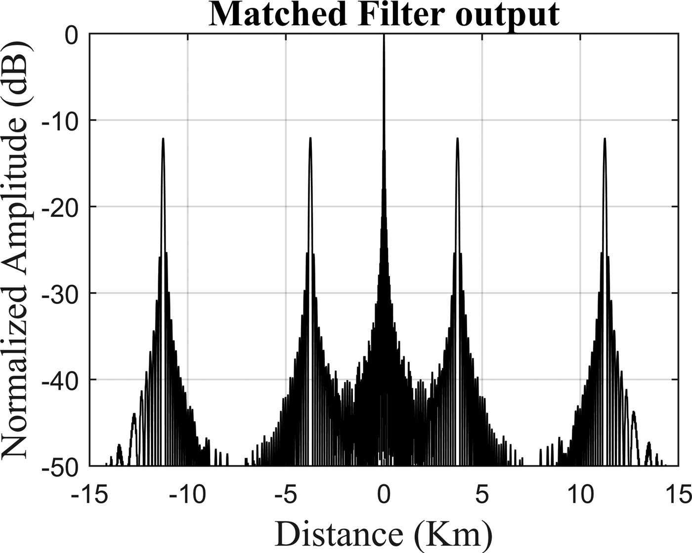
Figure 12 shows the simulation results of spectrum-dividing jammer when T = 100 µs, B = 5 MHz, and N = 4. In this case, the false targets are located at −11.25, −3.75, 3.75, and 11.25 km, respectively, and the relative distance between each adjacent false target equals 7.5 km.
The simulation results of spectrum-dividing repeater jammer.

The main advantage of spectrum-dividing jamming is its ability to generate false targets with different range while achieving a coherent processing gain. However, the jamming signals are parts of the radar pulse. Therefore, the jammer has to increase its power in order to compensate for this loss.
V. CONCLUSIVE REMARKS
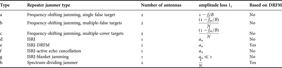
The properties of each presented jammer are summarized in Table 1.
The properties of different jammers.

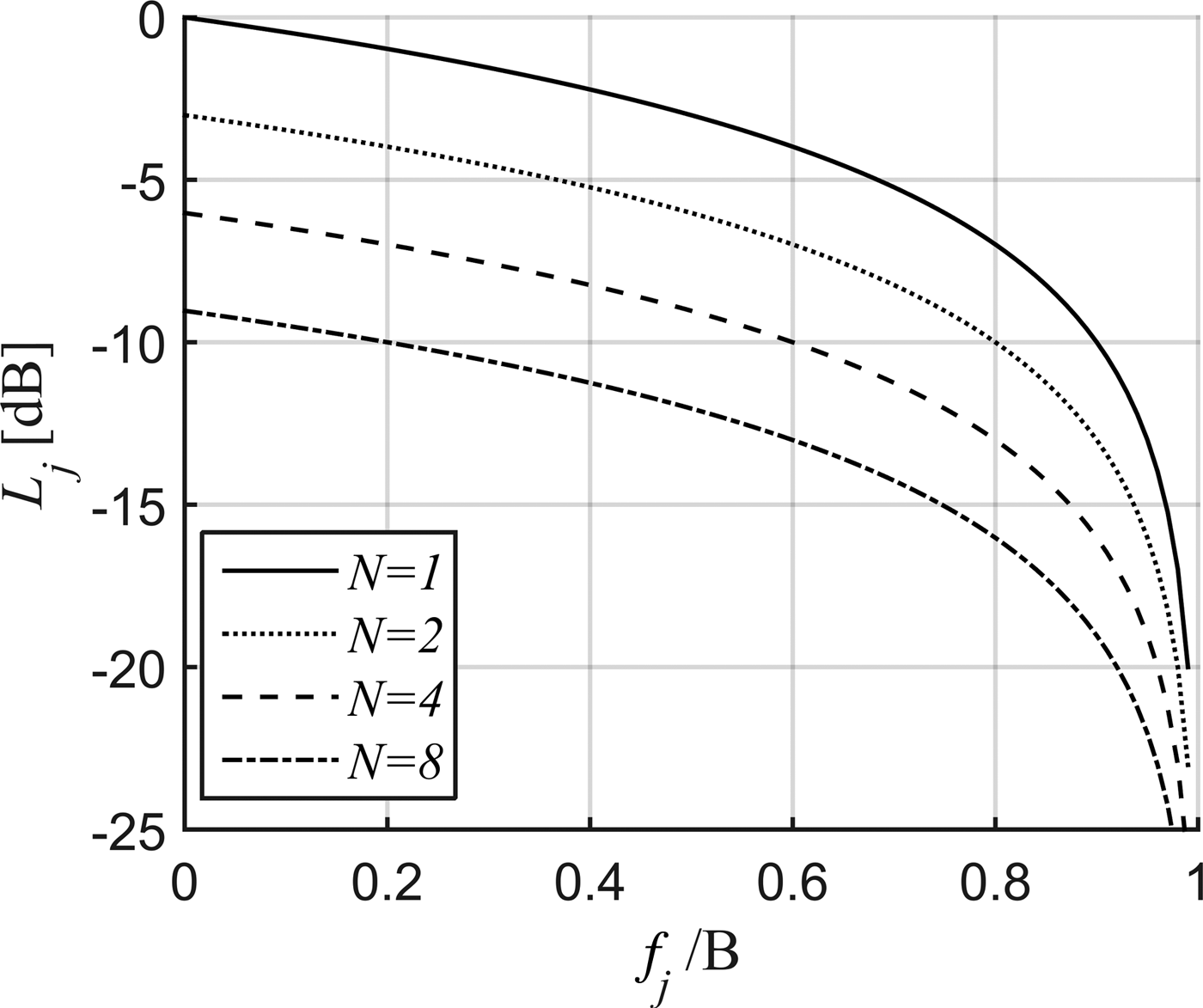
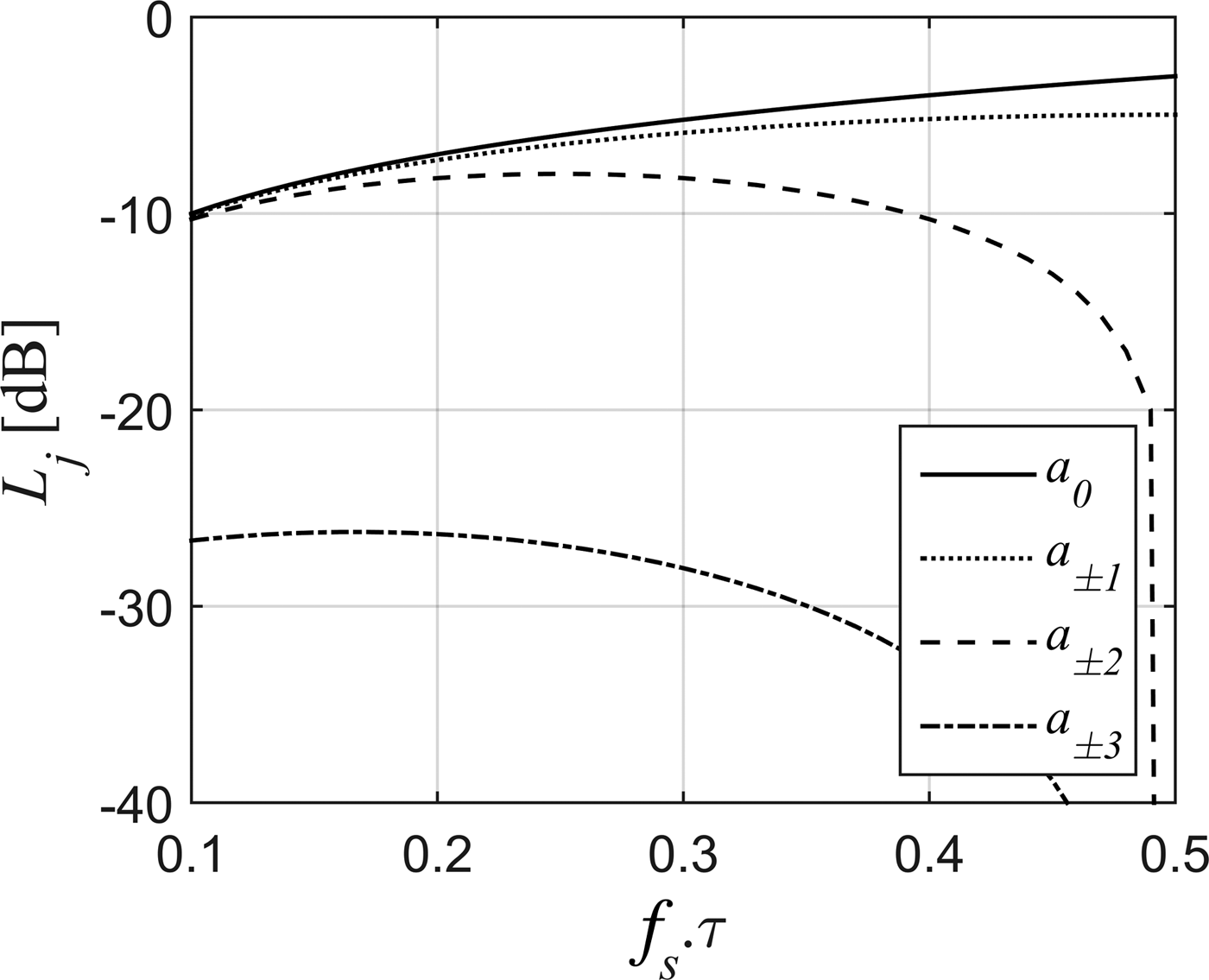
The jamming signal processing causes amplitude loss L j , which should be compensated by the jammer amplifier gain A j ≥ 1/L j and jammer antenna gain G j . Figures 13 and 14 show the loss (L j ) for different jamming types.
Jammer loss in the case of frequency-shifting jamming and spectrum-dividing jammer (when f j /B = 0).

Jammer loss in the case of ISRJ.

In self-protection jammer, the propagation loss is applied equally on both true target echo and jamming signals. However, the jamming signal has an advantage over the true target echo by a factor of (A j + G j ) dB. Therefore, jamming signal confuses the radar to a high degree, especially at far distances where the true target echo is weak.
The comparison between the presented jammers is summarized as follows:
-
(1) The main disadvantage of the frequency-shifting jammer is the need of a high isolation of two receive–transmit antennas, which might be difficult to implement. Therefore, ISRJ with a receive–transmit time-sharing antenna is preferred.
-
(2) When the deceptive jammer shifts the radar signal by a single frequency as shown in Table 1 (type a) and Fig. 13, the amplitude of false target is lower than the amplitude of true one, especially for high values of f j , because of the frequency mismatch between jamming signal and matched filter [Reference Yong, Zhang and Yang5]. However, more jamming power is required when the deceptive jammer divides radar pulse into N parts as shown in Table 1 (types b, c, and h) and Fig. 13, because the jamming signals are parts of the radar pulse [Reference Yong, Zhang and Yang5, Reference Pan, Wang, Feng, Fu and Wang7].
-
(3) When jamming types (d, e, and f) are used, the false targets are scaled by a n (a n is a function of f s τ) as shown in Fig. 14. On the other hand, when jamming type (g) is used, the jamming signal does not benefit from the gain of the matched filter (a n ≪ 1 as shown above). Therefore, the jammer has to increase its transmitted power to a high degree in order to disable the radar's capability for detecting the true target.
-
(4) Some presented jammers are based on DRFM, such as types (e and h) as shown in Table 1. Therefore, they can be countered by using traditional electronic counter-countermeasures (ECCM) techniques.
-
(5) ISRJ generates many false targets without sampling and storing the complete radar pulse, unlike spectrum-dividing jammer that samples and stores the complete radar pulse. Therefore, more memory is required in jamming system.
-
(6) ISRJ and spectrum-dividing jammer generate many false targets without the need to do complex frequency modulation used by frequency-shifting jammers.
-
(7) ISRJ with a receive–transmit time-sharing antenna can be carried by a missile easily, unlike two receive–transmit antennas used by frequency-shifting jammers.
The presented jammers in Table 1 degrade the performance of radar receiver as follows:
-
(1) Unfortunately, the optimum detection of chirp signals by a matched filter cannot distinguish the true target from the false one in the time domain, because they are interchangeable in time, i.e. the false target may come before or after the true one; also in the frequency domain, their spectra may be overlapping, which make them impossible to isolate.
-
(2) In jamming types (a, b, c, d, e, f, and h), the false targets look like the true targets at the output of radar-matched filter. When high JSR is used, a mutual target masking occurs; the strong false target that falls within the constant false alarm rate (CFAR) reference window will bias the threshold. Consequently, the conventional CFAR masks the weaker of the two closely spaced targets. Therefore, a modified CFAR is used such as trimmed mean or censored CFAR, and order statistics CFAR, which are designed to suppress mutual target masking. But these methods are not enough alone to counter deceptive jammers and to recognize the true target. In addition, they exhibit additional complexity, higher computational cost, and a higher CFAR loss, in terms of signal-to-noise ratio (SNR), above the conventional CFAR due to the use of lower number of cells [Reference Richards11, Reference Richards, Scheer and Holm12].
-
(3) When high JSR is used in jamming type (g), the jamming signal increases the detection threshold. Therefore, the true target echo is beneath the threshold. The covering distance of noise should be equivalent or larger than the detection window of CFAR detection [Reference Tai, Yuan and Pan10].
The commonly used (ECCM) techniques are effective against some types of deceptive jammers. Pulse repetition interval (PRI) jitter technique identifies the false targets returns if the deception jammer uses a delay that is greater than a PRI period to generate false targets return [Reference Adamy13], but this technique is inefficient in the case of instantaneously retransmitting the radar pulse after frequency-shifting or interrupted sampling during the radar chirp itself. The frequency agility technique changes the radio frequency of radar to make it impossible to know what the radio frequency of the next pulse will be, but if the jammer has a digital instantaneous frequency measurement receiver that measures approximately the first 50 ns of a pulse, it can quickly set to that radio frequency because modern radars typically have pulses of several microseconds long [Reference Adamy13]. Orthogonal waveforms technique transmits successive orthogonal waveforms that have low cross-correlation [Reference Deng14], and when the jammer pulse lags behind the true target pulse, it will not benefit from the pulse compression gain, a situation that is not applicable in the case of frequency-shifting jammer or ISRJ.
Recently, a method is proposed to remove the ISRJ-based false targets by using short-time Fourier transform [Reference Gong, Wei and Li15], where it was found that the time–frequency characteristics of the ISRJ signal are discontinuous in the pulse duration, because the ISRJ jammer needs short durations to receive the radar signal. Based on the discontinuous characteristics, a particular band-pass filter can be generated to retain the true target signal and suppress the ISRJ signal, but this method needs a high SNR to counter ISRJ because it is done before the pulse compression process. In addition, this is only applicable to counter ISRJ in the case of de-chirping radar (stretch processing).
We addressed countering some types of frequency-shift jammers for the first time using sweep bandwidth agility [Reference Hanbali and Kastantin16]. In that paper, the sweep bandwidth of the transmitted chirp was changed slightly, then the relative distances between the true target and the false ones changed. Consequently, false targets appeared in different range bins, but the true target remained in the same range bin, because the jammer frequency shift is much bigger than the Doppler shift of the true target. By doing that the radar range resolution and the matched filter gain do not degrade too much. Recently, we proposed a new anti-jamming technique based on the fractional Fourier transform (FrFT) at the radar receiver to counter different types of frequency-shift jammers against surveillance radars [Reference Hanbali and Kastantin17]. In that paper, the FrFT compresses the received signal in such a manner that the true target echo and the jamming signal are resolved, so that they are separated. Then, after FrFT compression and separation, the resulting signals are returned to the frequency domain where their spectra are compensated for Doppler shift, and then compared with spectrum of the original radar chirp in terms of the center frequency and the bandwidth. The signal that has less differences of the center frequency and sweep bandwidth is considered as the true target. We also addressed countering active echo cancellation of self-protection ISRJ for the first time by introducing a linear phase shift of the transmitted radar signal [Reference Hanbali and Kastantin18]. By doing that, the true target and the jammer echo will be in phase. Consequently, the true target power is augmented by jammer echo, converting the jamming signal from being malicious to beneficial.
VI. CONCLUSION
This paper reviewed different types of deceptive jammers against chirp radars. These jammers generate many false targets that appear before and after the true target. Unfortunately, the radar cannot distinguish the true target from the false one, because the true target echo and jamming signals overlap in time and frequency domains. The presented simulation of jamming systems, jammers comparison, and ECCM techniques are helpful for researchers in electronic warfare field.
ACKNOWLEDGEMENT
The authors would like to thank Hatem Najdi for his helpful discussions and for reviewing the final version of this paper.
 Samer Baher Safa Hanbali received the B.Sc. degree in Electronic Engineering from Damascus University, Syria, in 2000, and the M.Sc. degree from FH Joanneum, Austria, in 2011. He is pursuing the Ph.D. degree, in the area of Radar Signal Processing, at the Department of Communication Engineering in the Higher Institute of Applied Sciences and Technology, Damascus, Syria.
 Radwan Kastantin received the B.Sc. degree in Electronic Engineering from Damascus University, Syria, in 1986, and the Ph.D. degree from ICP-INPG, France, in 1996. He is a Professor of communication and signal processing at the Department of Communication Engineering in the Higher Institute of Applied Sciences and Technology, Damascus, Syria.