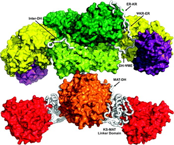
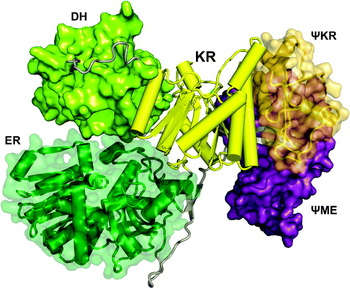
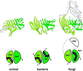
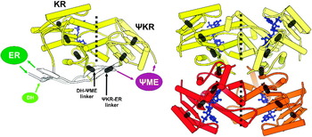
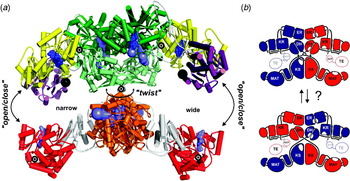
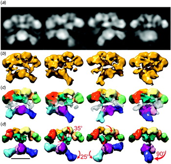
1. Introduction
Fatty acids are essential components of virtually all cells and fulfill a variety of functions. They are key constituents of most cell membranes in the form of their glycerol esters and serve as long-term energy storage compounds. Moreover, they can have regulatory roles as second messengers or covalent modifiers affecting protein translocation. Their biosynthesis is an essential process for most organisms and follows a conserved iterative pathway for stepwise precursor elongation by two-carbon (C2) carboxylic acid building blocks in more than 40 individual reactions involving at least seven different enzymes. In bacteria and plants, fatty acid biosynthesis is carried out by individual, monofunctional enzymes in a dissociated fatty acid biosynthesis system (Rock & Jackowski, Reference Rock and Jackowski2002), historically also termed as type II fatty acid synthase (FAS) system (Brindley et al. Reference Brindley, Matsumur and Bloch1969). Contrastingly, eukaryotes carry out fatty acid biosynthesis in large, multifunctional FAS enzymes (type I systems; Brindley et al. Reference Brindley, Matsumur and Bloch1969) that integrate all required enzymatic activities into unique assembly line complexes. Surprisingly, two strikingly different FAS multienzymes have evolved in animals and in fungi. Although these multifunctional FAS complexes have served as a paradigm for understanding and studying fatty acid biosynthesis and multienzyme mechanisms in general for the last 60 years, it is only recently that crystallographic structure determination has revealed the structures and organizational principles of eukaryotic FASs. This review focuses on the methods and difficulties associated with crystallization and X-ray crystallographic structure determination of both fungal and animal FASs and key conclusions regarding their biological function based on the available atomic models.
2. Historic perspective
2.1 The chemistry of fatty acid biosynthesis
In the middle of the last century, a series of outstanding discoveries culminated in the elucidation of the fatty acid biosynthetic route now known to every student from textbooks. A first milestone was the realization that fatty acids are built from condensed C2 building blocks, which was demonstrated by rat feeding experiments with radiolabeled acetate (Rittenberg & Bloch, Reference Rittenberg and Bloch1944). Based on experiments performed in his own and other laboratories, Lippman concluded in 1953 that the activated form of acetic acid used in lipid synthesis was acetyl-coenzyme A (acetyl-CoA) (Klein & Lipmann, Reference Klein and Lipmann1953a, Reference Klein and Lipmannb). By the same time, the mitochondrial β-oxidation pathway for fatty acid degradation had been unraveled (Lynen, Reference Lynen1953; Mahler, Reference Mahler1953), and for several years it was believed that the fatty acid biosynthesis was the reversal of fatty acid degradation by β-oxidation (Lynen, Reference Lynen1964). However, in 1958, it was demonstrated that acetic acid is first carboxylated to malonyl-CoA prior to decarboxylative condensation into fatty acids (Brady, Reference Brady1958; Wakil, Reference Wakil1958). Soon after, the stoichiometry of the fatty acid synthesis reaction was established for animal enzyme systems from different tissues (Brady, Reference Brady1960; Brady et al. Reference Brady, Bradley and Trams1960; Wakil, Reference Wakil1961; Wakil & Ganguly, Reference Wakil and Ganguly1959). Wakil also observed that acetyl-CoA was needed for the initial round of the elongation cycle, and therefore served as a primer, from which the fatty acid carbon chains are built up by successive addition of C2 units (Wakil & Ganguly, Reference Wakil and Ganguly1959). In 1961, Lynen, who had been working with the yeast FAS complex, proposed that the acyl intermediates remain covalently attached to the multifunctional enzyme via a thioester bond during the fatty acid biosynthetic cycle (Lynen, Reference Lynen1961). The experimental evidence for this was the lack of free reaction intermediates, the inactivation of yeast FAS by sulfhydryl-group modifying chemicals and the identification of enzyme-bound acetoacetate. The other reaction intermediates were verified from experiments with free substrate analogs. Soon after, the groups of Wakil and Vagelos found that in bacteria, the growing fatty acids remained covalently linked to a phosphopantetheine prostethic group of a small protein during the reaction cycle, which they termed the acyl carrier protein (ACP) (Majerus et al. Reference Majerus, Alberts and Vagelos1965; Pugh & Wakil, Reference Pugh and Wakil1965). Furthermore, they demonstrated that the phosphopantetheine prosthetic group was attached to a serine side chain of ACP and that reaction intermediates coupled to this protein were preferred substrates for the enzymes of fatty acid biosynthesis. The identification of equivalent carrier proteins from animal (Roncari et al. Reference Roncari, Bradshaw and Vagelos1972) and yeast FAS (Willecke et al. Reference Willecke, Ritter and Lynen1969), as well as the isolation of active individual enzymes from the multienzymatic animal and yeast FAS systems turned out to be difficult. However, until the late 1960s, almost all catalytic enzymes had been isolated and biochemically characterized from plants or bacteria, from which they could be readily purified (reviewed by Volpe & Vagelos, Reference Volpe and Vagelos1973). In 1969, Bloch discovered a multifunctional FAS complex from Mycobacterium phlei that displayed characteristics very similar to the yeast enzyme and he found that M. phlei contains a second, independent FAS system with dissociated enzymes (Brindley et al. Reference Brindley, Matsumur and Bloch1969). Based on these observations and the knowledge accumulated during the last decade, he proposed a new nomenclature: he termed the FAS systems found in bacteria and plants, which consisted of individual enzymes, ‘FAS type II’, in order to distinguish them from the animal or the fungal, which were purified as large, multifunctional complexes (‘FAS type I’). By that time, the multifunctional enzymes still were thought to be stable assemblies of individual enzymes, and only in the early 1970s it became clear that the type I FASs in fact consist of multifunctional polypeptide chains encoded by large genes, and not of assembled individual enzymes (Schweizer et al. Reference Schweizer, Kniep, Castorph and Holzner1973; Stoops et al. Reference Stoops, Arslanian, Oh, Aune, Vanaman and Wakil1975). Domain mapping, genetic studies and the publication of the primary structures of animal and yeast FAS in the 1980s showed that although both systems are classified as ‘FAS type I’, the animal and yeast enzymes have a radically different domain organization and therefore evolved along two unrelated lines (Amy et al. Reference Amy, Witkowski, Naggert, Williams, Randhawa and Smith1989; Mohamed et al. Reference Mohamed, Chirala, Mody, Huang and Wakil1988; Schweizer et al. Reference Schweizer, Roberts, Holtke, Takabayashi, Hollerer, Hoffmann, Muller, Kottig and Schweizer1986).
2.2 The swinging arm hypothesis
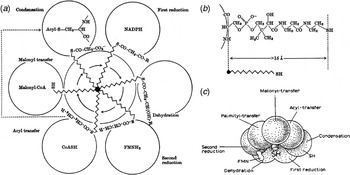
The ‘flexible arm’ hypothesis, a concept where a long prosthetic group, which is centrally attached to a multifunctional enzyme and carries a substrate between different catalytic sites during a multistep reaction, was first discussed in the early 1960s in the context of the electron flow within the α-ketoglutaric dehydrogenase complex. In this complex, the flexible prosthetic group covalently attached to a lysine side chain of the enzyme is a lipoyl moiety that transfers electrons from one active site to another (Green & Oda, Reference Green and Oda1961). During the following years, the concept was adopted for other prosthetic groups found in enzyme complexes such as biotinylated lysines in carboxylases (reviewed in Knowles, Reference Knowles1989) and phosphopantetheinylated serines in FASs (Fig. 1) (Lynen, Reference Lynen1967). The general term ‘swinging arm’ (‘Schwingarm’) was established for the yeast FAS complex in the late 1960s by Lynen (Sumper et al. Reference Sumper, Oesterhelt, Riepertinger and Lynen1969) and was used to describe how the fatty acid reaction intermediates, which remain covalently attached to the FAS via the phosphopantetheine, are shuttled between the different active sites.
Illustrations of the ‘swinging arm hypothesis’ for yeast FAS. (a, b) During the cyclic fatty acid biosynthesis, the reaction intermediates remain attached to a central phosphopantetheine arm, which is covalently linked to the enzyme. The length and flexibility of the swinging arm allow it to reach all the catalytic enzymes surrounding it. (c) Model of the multifunctional yeast FAS complex based on the swinging arm concept. (a–c) Reproduced with permission from Lynen (Reference Lynen1967) © the Biochemical Society.

However, in the late 1970s, when more structural information for the yeast FAS complex became available (see next paragraph), Lynen noted that the length of the phosphopantetheine arm (~20 Å) would not be sufficient to overcome distances of up to 100 Å by simple rotation of the swinging arm alone, and he proposed that ‘part of the protein must also be involved in this transport processes’ (Lynen, Reference Lynen1980). Indeed, a possible candidate, the phosphopantetheine-containing, proteolytic 16 kDa fragment corresponding to yeast FAS ACP had been detected and analyzed earlier (Schreckenbach et al. Reference Schreckenbach, Wobser and Lynen1977; Willecke et al. Reference Willecke, Ritter and Lynen1969). Since then, the emerging ‘swinging domain’ concept has been corroborated in several cases, such as the pyruvate dehydrogenase complex (Perham, Reference Perham2000).
2.3 Structural investigation of fungal FAS by cross-linking analysis and electron microscopy (EM)
Until the early 1970s, based on different separation techniques, it was believed that yeast FAS consists of 6–7 isolated subunits that assemble into a large, stable and rigid complex with the ACP fixed centrally to reach all catalytic domains with its flexible phosphopantetheine arm, and research focused on isolation and analysis of these individual components (Fig. 1c) (Lynen, Reference Lynen1967). Then, contrasting results emerged from genetic and biochemical analysis, which indicated that yeast FAS consists of only two multifunctional polypeptides (termed chains α and β, respectively) encoded by unlinked genes (fas2 and fas1) (Schweizer et al. Reference Schweizer, Kniep, Castorph and Holzner1973; Stoops et al. Reference Stoops, Arslanian, Oh, Aune, Vanaman and Wakil1975). It became clear that the numerous individual proteins previously detected had been the result of unspecific proteolysis during the preparation. At the beginning of the 1980s, the active site peptides of several catalytic domains had been identified and the catalytic activities had been further characterized biochemically (Lynen, Reference Lynen1980), but the location of the catalytic residues within both multifunctional polypeptides and the approximate domain borders could only be reliably established when the primary structures of both yeast FAS subunits were published in the middle of the 1980s (Mohamed et al. Reference Mohamed, Chirala, Mody, Huang and Wakil1988; Schweizer et al. Reference Schweizer, Roberts, Holtke, Takabayashi, Hollerer, Hoffmann, Muller, Kottig and Schweizer1986), which enabled further mutagenesis experiments (Fichtlscherer et al. Reference Fichtlscherer, Wellein, Mittag and Schweizer2000; Schuster et al. Reference Schuster, Rautenstrauss, Mittag, Stratmann and Schweizer1995).
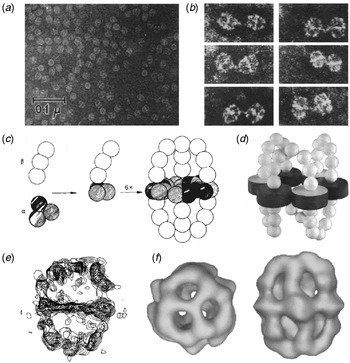
For the understanding of such a complex multienzyme, the knowledge of its three-dimensional (3D) structure is of critical importance, and consequently structural studies on fungal FAS were pursued in parallel with its biochemical and genetic characterization. In 1964, Lynen interpreted the FAS particles on a negatively stained electron micrograph as ‘hollow oval particles surrounded by an equatorial ring’ with dimensions of 210 Å×250 Å (Lynen, Reference Lynen1964) (Fig. 2a). He speculated that the FAS particle might ‘consist of three rings packed one inside another’ with three complete sets of active sites. In 1970, the yeast FAS was further characterized by small angle X-ray scattering (SAXS), which confirmed the hollow interior of the particle (Pilz et al. Reference Pilz, Herbst, Kratky, Oesterhelt and Lynen1970). Theoretical considerations further suggested a spherical, 20 Å thick outer wall of the particle and a division of its interior into halves by an equally thick central plate, and the authors argued that if the swinging arms were attached to the central plate, such an arrangement would allow it to contact the enzymes distributed in the peripheral wall. The discovery that the particle with its estimated molecular weight of ~2·4 MDa is composed of two kinds of polypeptide chains, each with a size of ~200 kDa, and that the flavin mononucleotide (FMN) cofactor and pantetheine content was about one mole per two subunits lead to the conclusion that the complex forms a heterododecameric α6β6 assembly (Kresze et al. Reference Kresze, Oesterhelt, Lynen, Castorph and Schweizer1976; Stoops et al. Reference Stoops, Awad, Arslanian, Gunsberg, Wakil and Oliver1978b). The distribution of the α- and β-chains within the complex was elegantly shown by antibody cross-link experiments in combination with negative stain EM, which revealed that upon treatment with anti-α-chain antibodies, FAS particles were connected via the central disc, whereas anti-β-chain antibodies linked the complexes at the dome-like protrusions on both sides of the disc (Fig. 2b) (Wieland et al. Reference Wieland, Siess, Renner, Verfurth and Lynen1978). Taking all this biochemical and structural information into account, a model for the architecture of the yeast FAS was presented by Lynen and co-workers (Fig. 2c) (Wieland et al. Reference Wieland, Siess, Renner, Verfurth and Lynen1978). A related model was proposed by Wakil's group, which was derived from stereoscopic EM images and specific cross-linking of neighboring α-chains (Fig. 2d) (Stoops & Wakil, Reference Stoops and Wakil1980, Reference Stoops and Wakil1981; Stoops et al. Reference Stoops, Awad, Arslanian, Gunsberg, Wakil and Oliver1978b); the authors further concluded that an α2β structure represents the minimal functional unit of the heterododecameric complex (Stoops & Wakil, Reference Stoops and Wakil1981). For a long time, it remained unclear whether the internal symmetry of the FAS particle is C2 or D3. Attempts to determine the particle's symmetry by tomographic 3D EM reconstructions corroborated the overall shape of the proposed models, but due to limited resolution, the symmetry operators could not be established unambiguously, although a D3 symmetry seemed more likely (Fig. 2e) (Hackenjos & Schramm, Reference Hackenjos and Schramm1987; Hoppe et al. Reference Hoppe, Gassmann, Hunsmann, Schramm and Sturm1974, Reference Hoppe, Schramm, Sturm, Hunsmann and Gassmann1976). It was not until the 1990s that 3D cryo-EM finally revealed the internal D3 symmetry of the FAS particle (Kolodziej et al. Reference Kolodziej, Penczek and Stoops1997; Stoops et al. Reference Stoops, Kolodziej, Schroeter, Bretaudiere and Wakil1992) (Fig. 2f). However, because the resolution of the reconstructions was limited and high-resolution X-ray structures of isolated domains or bacterial FAS type II homologues were unavailable, the assignment of individual domains to specific regions of the particle was not possible.
Models of yeast FAS based on EM and cross-linking studies. (a) Early negative stain electron micrograph showing yeast FAS particles. (b, c) The negative stain EM micrographs of FAS particles cross-linked with antibodies raised against the β-chain reveal cross-linking via the domes (left panels), whereas particles cross-linked with anti-α-chain antibodies are connected at the central disc (right panels). The model of FAS derived from these experiments is shown in (c). (d) Model proposed by the Wakil group, which is based on stereoscopic EM micrographs and chemical cross-linking of neighboring α-chains. (e) Electron density contour map of an early 3D negative stain electron tomography reconstruction of the FAS particle. (f) 3D cryo-EM reconstruction of the FAS complex determined to 21 Å resolution. Although in the top and side views, the central disc and the arch-like domes of particless are readily visible, the limited resolution does not allow the assignment of individual domains. (a) Reproduced with permission from Lynen (Reference Lynen1967) © the Biochemical Society, (b, c) adapted with permission from Wieland et al. (Reference Wieland, Siess, Renner, Verfurth and Lynen1978), (d) modified with permission from Stoops & Wakil (Reference Stoops and Wakil1980), (e) adapted with the permission of Walter de Gruyter from Hackenjos & Schramm (Reference Hackenjos and Schramm1987) and (f) reprinted from Kolodziej et al. (Reference Kolodziej, Penczek and Stoops1997) with the permission of Elsevier.

2.4 Models of animal FAS based on biochemical and electron microscopic analysis
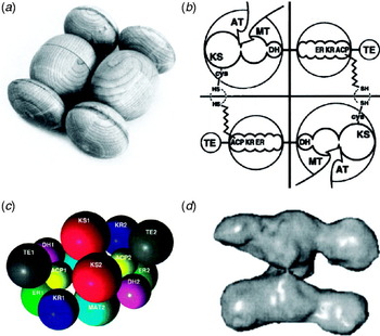
In a first step towards the understanding of fatty acid biosynthesis in animal tissue, Brady and Gurin demonstrated in 1952 the production of fatty acids in cell-free systems of water-soluble enzymes from pigeon liver (Brady & Gurin, Reference Brady and Gurin1952). During the following decade, the underlying chemical reactions and the cofactor requirements for fatty acid biosynthesis were revealed in the laboratories of Lynen, Wakil, Vagelos and others (Lynen, Reference Lynen1961; Martin et al. Reference Martin, Horning and Vagelos1961; Wakil et al. Reference Wakil, Sauer and Pugh1964). In the 1970s, the enzymes of fatty acid biosynthesis in animals, the animal FAS, was purified to homogeneity and characterized as a single, multifunctional enzyme complex with an approximate molecular weight of 500 kDa (Stoops et al. Reference Stoops, Arslanian, Oh, Aune, Vanaman and Wakil1975) composed of two identical polypeptide chains (Mattick et al. Reference Mattick, Zehner, Calabro and Wakil1981; Smith & Stern, Reference Smith and Stern1979; Stoops et al. Reference Stoops, Arslanian, Aune and Wakil1978a). Cross-linking studies in combination with biophysical characterization by solution scattering, negative stain EM and analytical ultracentrifugation resulted in first structural models, depicting animal FAS as a head-to-tail dimer of two elongated approximately 200 Å long-segmented monomers (Fig. 3a, b) (Smith et al. Reference Smith, Stern, Randhawa and Knudsen1985; Stoops et al. Reference Stoops, Wakil, Uberbacher and Bunick1987) with two simultaneously acting sets of reaction sites (Fig. 3b) (Singh et al. Reference Singh, Wakil and Stoops1984; Tsukamoto et al. Reference Tsukamoto, Wong, Mattick and Wakil1983). The cloning and sequencing of cDNA from animal FAS of several different species allowed a detailed analysis of the domain organization and enabled the assignment of active site amino acids (Amy et al. Reference Amy, Witkowski, Naggert, Williams, Randhawa and Smith1989; Huang et al. Reference Huang, Chirala and Wakil1994; Witkowski et al. Reference Witkowski, Rangan, Randhawa, Amy and Smith1991). Based on the sequence information and the ability to produce variants of animal FAS recombinantly, extensive mutant complementation studies were carried out in the lab of Stuart Smith (Witkowski et al. Reference Witkowski, Joshi and Smith1996). Combined with biophysical approaches, this work finally resulted in a description of domain interactions in animal FAS that was not consistent with the classic head-to-tail model of dimer organization, but rather suggested a head-to-head arrangement of the two subunits with a complex domain arrangement (Fig. 3c) (Rangan et al. Reference Rangan, Joshi and Smith2001). The availability of initial structures of bacterial monofunctional homologues of animal FAS domains led to an understanding of the conserved active site architecture for some of the animal FAS domains and revealed the dimeric nature of ketosynthase proteins. The incorporation of this knowledge into a revised model of animal FAS also revealed the central role of the ketosynthase domain in the organization of the dimer (Smith et al. Reference Smith, Witkowski and Joshi2003; Witkowski et al. Reference Witkowski, Ghosal, Joshi, Witkowska, Asturias and Smith2004). Due to the flexibility of the enzyme, the cryo-EM 3D reconstruction of animal FAS was not possible at resolutions better than about 20 Å, which was not sufficient for recognition of individual domains (Fig. 3d) (Brink et al. Reference Brink, Ludtke, Yang, Gu, Wakil and Chiu2002, Reference Brink, Ludtke, Kong, Wakil, Ma and Chiu2004). Consequently, the 3D arrangement of domains and the architecture for productive substrate transfer remained enigmatic.
Different models of the animal FAS structure. (a) Wooden model of chicken FAS based on small angle neutron scattering. (b) Proposed organization of chicken FAS based on cross-linking and partial digestion. (c) Conceptual intertwined head-to-head model. (d) Cryo-EM 3D reconstruction of human FAS at 23 Å resolution. (a) Modified from Stoops et al. (Reference Stoops, Wakil, Uberbacher and Bunick1987) © 1987 The American Society for Biochemistry and Molecular Biology, (b) modified from Tsukamoto et al. (Reference Tsukamoto, Wong, Mattick and Wakil1983) © 1983 The American Society for Biochemistry and Molecular Biology, (c) adapted with permission from Rangan et al. (Reference Rangan, Joshi and Smith2001) © 2001 American Chemical Society and (d) modified from Brink et al. (Reference Brink, Ludtke, Yang, Gu, Wakil and Chiu2002) © 2002 National Academy of Sciences, USA.

2.5 Early crystallization of eukaryotic FASs
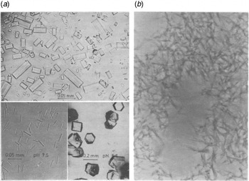
Crystallization of small molecules and also of proteins has a long tradition as a method of purification and as a proof of sample purity and integrity. Already in 1969, D. Oesterhelt in the Lynen lab, while working on the characterization of yeast FAS, obtained crystals from a solution of yeast FAS in 1·2 M ammonium sulfate left at 4°C for 15 months. Using these initial crystals as seeds, he grew crystals larger than 0·1 mm from ammonium sulfate conditions and determined in detail the pH and temperature optimum for crystallization (Oesterhelt et al. Reference Oesterhelt, Bauer and Lynen1969). All crystals were hexagonal prisms, but with varying ratios of diameter to length (Fig. 4a). He also demonstrated that yeast FAS crystallized within 2 days retained full enzymatic activity, and that the loss of activity after prolonged crystallization periods was due to damage to the condensing enzyme only that could be partially recovered by treatment with 10 mM cysteine (Oesterhelt et al. Reference Oesterhelt, Bauer and Lynen1969). In retrospect, this is very well explained by an oxidation of the highly reactive active site cysteine of the ketoacyl synthase (KS) domain. Since the work of Oesterhelt in 1969, to our knowledge, no further reports on the crystallization of fungal FAS have been published. The only crystals reported for animal FAS were tiny microcrystalline needles (Fig. 4b): In 1981, T. Linn purified animal FAS from rat liver by fractionation with ammonium sulfate and polyethylene glycol (PEG) 6000 precipitation followed by anion exchange and size exclusion chromatography (Linn, Reference Linn1981). For crystallization, Linn dissolved pellets from ammonium sulfate precipitation in a minimal amount of buffer at a final concentration of around 60–70 mg/ml and allowed this solution to stand for several hours. She also observed that rat FAS from re-dissolved crystals displayed full enzymatic activity.
Early crystallization of eukaryotic FASs. (a) Crystals of yeast FAS grown at different pH values (top: pH 6.5; bottom left: pH 7.5; bottom right: pH 5.5) with ammonium sulfate as a precipitant. (b) Microcrystals of rat FAS, original image taken at 1000× magnification with phase contrast under oil immersion. (a) Modified with permission from Oesterhelt et al. (Reference Oesterhelt, Bauer and Lynen1969) and (b) adapted from Linn (Reference Linn1981) with the permission of Elsevier.

3. Fungal FAS
3.1 Domain composition and biosynthetic cycle
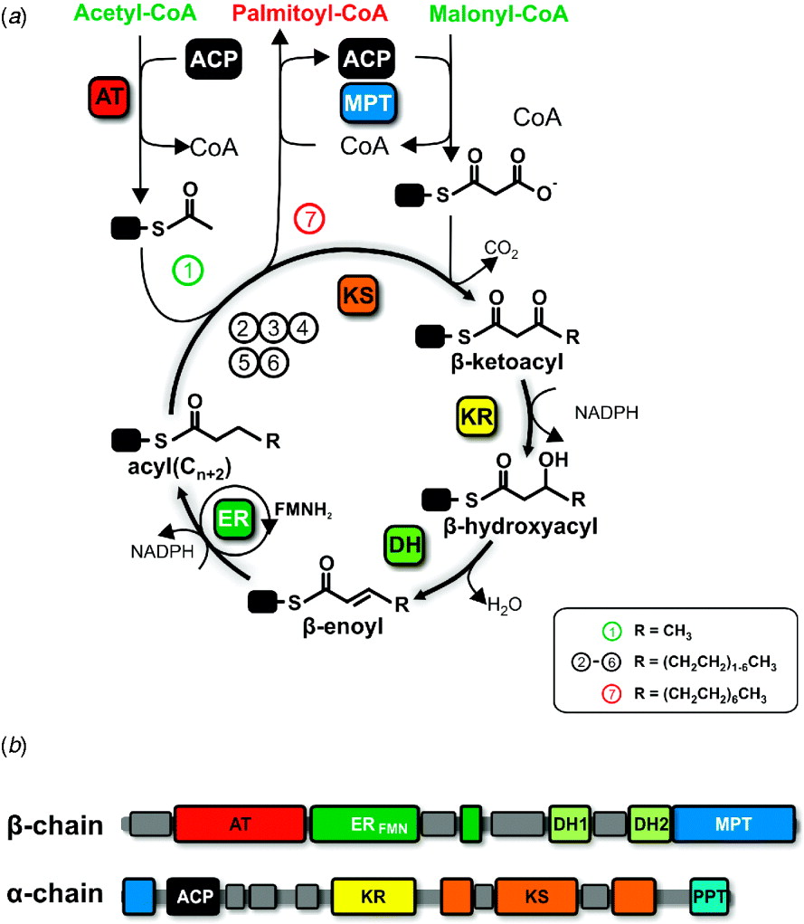
In the multienzymatic yeast FAS, all catalytic domains necessary to synthesize a fully saturated C16 fatty acid from the primer substrate acetyl-CoA and the elongation substrates malonyl-CoA and nicotinamide adenine dinucleotide phosphate (reduced form, NADPH) are distributed among two polypeptide chains (Fig. 5). The cyclic fatty acid elongation reaction (Fig. 5a) is initiated by the transfer of an acetyl moiety from acetyl-CoA to ACP, which is catalyzed by acetyl-transferase (AT). ACP then shuttles the acetyl primer to KS. In the next step, the bifunctional malonyl/palmitoyl transferase (MPT) charges the ACP with a malonyl moiety originating from malonyl-CoA. Malonyl-ACP subsequently condenses with the KS-bound acetyl primer under decarboxylation to form acetoacetyl-ACP in an irreversible reaction catalyzed by the KS. The next three steps, during which the reaction intermediates always remain attached to ACP and are modified at the β-carbon position, involve an NADPH-dependent reduction step by ketoacyl reductase (KR), followed by a dehydration step catalyzed by dehydratase (DH) and a second reduction step by the NADPH/FMN-dependent enoyl reductase (ER). Finally, ACP shuttles the saturated fatty acid, elongated by two carbon atoms, back to KS, where it serves as primer for the next reaction cycle. After 7 cycles, the resulting C16 (palmitoyl) moiety is back-transferred from ACP to CoA by MPT and released into the cytosol as CoA-thioester (Fig. 5a).
Catalytic cycle and linear domain organization of fungal FAS. (a) Catalytic cycle of fungal FAS. Acetyl-CoA serves as a starter substrate for iterative stepwise elongation by two carbon units donated from the elongator substrate malonyl-CoA in a decarboxylative condensation. Substrate loading is catalyzed by AT and MPT, the latter is also responsible for product release. KS catalyzes the decarboxylative condensation and KR, DH and ER are modifying the β-carbon position until full saturation. (b) Linear domain organization of fungal FAS, drawn approximately to sequence scale.

In addition to the domains directly involved in catalyzing the fatty acid elongation cycle, fungal FAS harbors a phosphopantetheine-transferase (PPT) domain at the C-terminus of the α-chain (Fig. 5b), which transfers the prosthetic phosphopantetheine group from a CoA substrate to a conserved serine of apo-ACP, thus auto-activating the FAS complex (Fichtlscherer et al. Reference Fichtlscherer, Wellein, Mittag and Schweizer2000).
3.2 Purification and crystallization of fungal FAS
Due to the complexity of the multienzyme that complicates cloning and recombinant protein expression, fungal FAS has been purified from native source organisms for all structural studies reported so far. As the natural expression levels are limited, large amounts of cells are required to obtain sufficient amounts of highly pure FAS for crystallization. Commercially available or easily fermentable yeast cells were used for most studies, although in one case Jenni et al. (Reference Jenni, Leibundgut, Maier and Ban2006) fermented the mildly thermophilic fungus Thermomyces lanuginosus as a source organism for FAS purification in a 200-liter scale, assuming that a thermostable enzyme might be more easily crystallized. The purification of fungal FAS has been carried out through a combination of sucrose cushion and sucrose gradient ultracentrifugation followed by ion exchange chromatography (Jenni et al. Reference Jenni, Leibundgut, Maier and Ban2006; Leibundgut et al. Reference Leibundgut, Jenni, Frick and Ban2007; Lomakin et al. Reference Lomakin, Xiong and Steitz2007), sometimes combined with fractionated ammonium sulfate precipitation (Jenni et al. Reference Jenni, Leibundgut, Maier and Ban2006; Leibundgut et al. Reference Leibundgut, Jenni, Frick and Ban2007). Johansson et al. chose a different strategy and used homologous recombination to produce a yeast strain expressing a C-terminally His8-tagged FAS β-chain and purified the intact FAS particle through metal chelate affinity chromatography followed by ultracentrifugation (Johansson et al. Reference Johansson, Wiltschi, Kumari, Kessler, Vonrhein, Vonck, Oesterhelt and Grininger2008).
Commercial crystallization screens targeted at crystallizing standard-sized proteins commonly use precipitants at concentrations too high for large macromolecular complexes. Consistently, the first reported diffracting fungal FAS crystals were obtained by crystallization screening of T. lanuginosus FAS with diluted commercial factorial screens. Refined conditions employing around 4% PEG6000 as precipitant in a sitting drop vapor diffusion setup yielded bipyramidal crystals with dimensions of 0·1×0·2×0·5 mm3. The crystals belonged to orthorhombic space group P212121 with unit cell dimensions of ~250×380×420 Å3, large enough to accommodate one molecule per asymmetric unit (ASU) with a solvent content of 66% (Jenni et al. Reference Jenni, Leibundgut, Maier and Ban2006). An analysis of the self-rotation function clearly showed the orientations of non-crystallographic symmetry (NCS) 2- and 3-fold axes (Jenni & Ban, Reference Jenni and Ban2009) expected for a particle with D3 symmetry. Upon stabilization in 1·4 M lithium sulfate as a cryoprotectant, the crystals diffracted to 8 Å resolution. In a search for a post-crystallization technique suited to improve the diffraction quality of these crystals, Jenni et al. discovered that stepwise increase of the PEG 6000 concentration to 23% during cryo-stabilization with 1,3-propanediol induced a space group transition of the crystals from the orthorhombic P212121 to the monoclinic space group P21 (unit cell dimensions of ~220×415×222 Å3, 1 molecule/ASU, 67% solvent content). These crystals diffracted initially to 4·2 Å (Jenni et al. Reference Jenni, Leibundgut, Maier and Ban2006) and after refining the crystal growth and stabilization conditions to about 3 Å resolution. However, they were pseudo–merohedrally twinned as a consequence of an energetically equivalent but directionally ambivalent breakdown of the orthorhombic crystal symmetry (Jenni & Ban, Reference Jenni and Ban2009; Jenni et al. Reference Jenni, Leibundgut, Maier and Ban2006, Reference Jenni, Leibundgut, Boehringer, Frick, Mikolasek and Ban2007). Still, extensive screening for slow dehydration procedures yielded crystals in which one of the two twin fractions was so weak that the other twin domain was essentially unaffected at higher resolution.
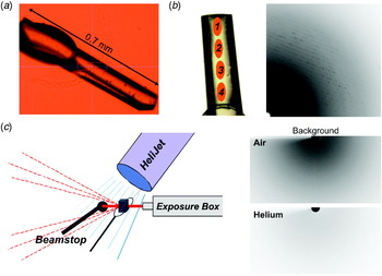
Later, three groups independently reported the crystallization of yeast FAS under related crystallization conditions, employing medium size PEGs (PEG 1500–4000) at around neutral pH and with added salt (potassium chloride or ammonium sulfate). The Steitz lab obtained two crystal forms, a particularly radiation-sensitive monoclinic form (P21, 217×347×263 Å3) and bipyramidal tetragonal crystals in space group P43212 with unit cell dimensions of a=b=231 Å and c=754 Å, which both diffracted weakly to 4 Å resolution (Lomakin et al. Reference Lomakin, Xiong and Steitz2007). The latter crystal form was also obtained in the Oesterhelt group with identical diffraction limits (Johansson et al. Reference Johansson, Wiltschi, Kumari, Kessler, Vonrhein, Vonck, Oesterhelt and Grininger2008). Leibundgut et al. however, obtained tetragonal crystals with related unit cell dimensions of a=b=231 Å and c=784 Å, but now in space group P41212, with a solvent content of 69% and half a FAS particle per ASU, which diffracted to about 3 Å resolution. To avoid a spatial overlap of reflections, the long c-axis had to be aligned to the spindle axis during data collection from yeast FAS crystals, which was achieved either using bent loops (Dauter, Reference Dauter1999; Johansson et al. Reference Johansson, Wiltschi, Kumari, Kessler, Vonrhein, Vonck, Oesterhelt and Grininger2008; Leibundgut et al. Reference Leibundgut, Jenni, Frick and Ban2007) or a kappa goniostat (Johansson et al. Reference Johansson, Wiltschi, Kumari, Kessler, Vonrhein, Vonck, Oesterhelt and Grininger2008).
3.3 Phasing and map interpretation
Generally, the crystallographic phase problem in macromolecular crystallography can either be solved by the molecular replacement technique which depends on correct positioning of a model for a substantial part of the structure to be solved in the ASU, or by multiple isomorphous replacement or single/multiple anomalous dispersion techniques that require solving a heavy atom substructure obtained by derivatization of native crystals. Nevertheless, these approaches can become increasingly difficult when solving structures of very large assemblies.
Although individual structural templates were known for most of the fungal FAS domains, each of them contained only less than 10% of the total mass of the molecule, not sufficient to obtain a molecular replacement solution. Therefore, the first strategy employed to solve the T. lanuginosus FAS structure was using an EM volume (Kolodziej et al. Reference Kolodziej, Penczek and Stoops1997) as a starting model for molecular replacement at low resolution, followed by 6-fold NCS averaging and phase extension to higher resolution. Although the position and orientation of the EM model could be determined, this approach failed to yield interpretable electron density maps, probably due to the limited resolution (21 Å) of the single particle reconstruction used as a starting model. The molecular replacement phases were not even powerful enough for locating heavy atom positions in difference Fourier maps (Mueller et al. Reference Mueller, Jenni and Ban2007).
The large ASUs of the FAS crystals (containing up to 24 000 residues) render the determination of a heavy atom substructure difficult (Jenni et al. Reference Jenni, Leibundgut, Maier and Ban2006; Mueller et al. Reference Mueller, Jenni and Ban2007). For example, approaches such as cysteine derivatization by covalent modification would result in ~150 heavy atom sites, which generate noisy Patterson maps that are very difficult to interpret. Therefore, the use of heavy atom clusters instead of single-atom scatterers offers several advantages for phasing: due to their size, only a limited number of binding sites can be expected, and at lower resolution, they can be treated as point scatterers with a very strong signal, due to the presence of several thousands of electrons per cluster (Dauter, Reference Dauter2005). This greatly reduces the complexity of Patterson maps and also enhances the chance to find a correct solution using automated search procedures.
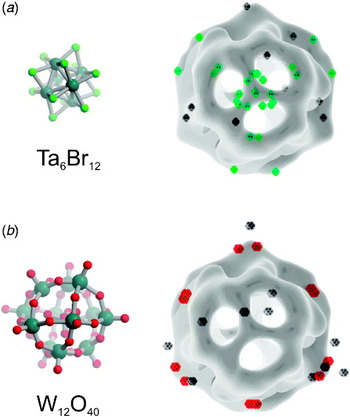
Experimental phasing was first successful for T. lanuginosus crystals. Because the better diffracting monoclinic crystal form was affected by twinning and therefore did not allow the measurement of a weak anomalous signal, Jenni et al. focused on the orthorhombic, un-twinned crystal form (Jenni et al. Reference Jenni, Leibundgut, Boehringer, Frick, Mikolasek and Ban2007). In the initial crystal-soaking experiments with several clusters, including Ta6Br12 and ‘W10’ (Cs5[γ-SiW10Cr2(CH2COOH)2]) (Fig. 6a, b), the heavy atoms could not be located, which was likely due to the presence of a large number of unspecific binding sites, despite the presence of a strong anomalous signal in several SAD datasets of these derivatives. Cluster soaking also generally increased the degree of non-isomorphicity between crystals, prohibiting structure determination through multiple isomorphous replacement with a larger number of derivatives (Mueller et al. Reference Mueller, Jenni and Ban2007). However, after extensive back-soaking of crystals to remove poorly occupied sites, an 8 Å SAD dataset of Ta6Br12-derivatized crystals was collected at the tantalum absorption edge, which permitted the location of 34 Ta6Br12 sites (Jenni et al. Reference Jenni, Leibundgut, Maier and Ban2006) by direct methods as implemented in SHELXD (Sheldrick, Reference Sheldrick2008). The observed 2- and 3-fold symmetric relationship of many of these sites indicated the correctness of the solution (Fig. 6a). The location of sites and the correct handedness was also confirmed by inspection of an anomalous difference cross Fourier map calculated with the W10 data and Ta6Br12 SAD phases, which again revealed several 2- and 3-fold related W10 sites (Jenni et al. Reference Jenni, Leibundgut, Maier and Ban2006) (Fig. 6b).
Derivatization of T. lanuginosus FAS with heavy atom cluster compounds. (a) Structure (left) and binding sites (right) of the Ta6Br12 cluster. The positions of the clusters were identified by direct method search procedures based on single-wavelength anomalous dispersion data. (b) Structure of the W12O40 cluster (left), representing the core structure of the W10-cluster used for derivatization of FAS. Right: binding sites of this cluster obtained through cross-anomalous difference map calculation based on phases obtained from Ta6Br12 derivatization. In (a) and (b), a large number of the observed binding sites are located around the surface of the particle, approximately outlined here by a low resolution EM volume (Kolodziej et al. Reference Kolodziej, Penczek and Stoops1997), and they obey the expected 3-fold symmetry.

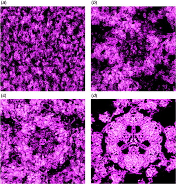
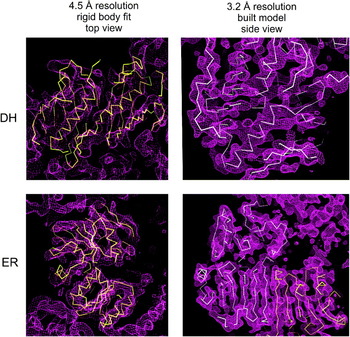
The Ta6Br12 phases were considerably improved by solvent flipping (Abrahams & Leslie, Reference Abrahams and Leslie1996; Jenni et al. Reference Jenni, Leibundgut, Maier and Ban2006; Mueller et al. Reference Mueller, Jenni and Ban2007), which is particularly powerful for large unit cells (Fig. 7) (Abrahams & Ban, Reference Abrahams and Ban2003). The modified phases were then used as starting phases for phase extension in the high-resolution monoclinic space group by multi-crystal and 6-fold intra-crystal NCS averaging (Cowtan, Reference Cowtan1994) using three different datasets: the orthorhombic 8·0 Å Ta-derivative and, to obtain completeness in particular at low resolution, two native monoclinic datasets, one of which diffracted to 8·0 Å, and the other to 4·2 Å resolution. The precise positioning and envelopes of averaging masks and the determination of averaging operators were guided by self-rotation function analysis and the molecular replacement solution obtained using the EM starting model (Jenni et al. Reference Jenni, Leibundgut, Maier and Ban2006; Mueller et al. Reference Mueller, Jenni and Ban2007).The resultant intermediate resolution electron density maps were well phased to beyond ~5 Å resolution with clearly resolved secondary structure elements (Jenni et al. Reference Jenni, Leibundgut, Maier and Ban2006).
Experimental electron density maps of T. lanuginosus FAS. (a)–(c) Experimental electron density maps of fungal FAS at 8 Å resolution based on Ta6Br12 derivatization directly after SAD phasing (a), after solvent flipping (b) and after NCS averaging (c). (d) Final experimental electron density map at 3·1 Å resolution after domain-wise NCS averaging and solvent flipping.

Due to the limited resolution, the interpretation of this density map was based only on the identification of discrete domains and rigid-body fitting of high-resolution structures of FAS type II homologues (Jenni et al. Reference Jenni, Leibundgut, Maier and Ban2006), which were available for most fungal FAS domains (White et al. Reference White, Zheng, Zhang and Rock2005). Visual inspection of the map along the 2-fold NCS axes allowed the location of KS and KR domains, which were known to dimerize (or tetramerize) in FAS type II systems (Jenni et al. Reference Jenni, Leibundgut, Maier and Ban2006). The positioning of the bacterial malonyltransferase (MT) homologue revealed two regions of electron density, one representing the fungal AT and the other the MPT, which both match the fold of this domain. Only when the large β-sheet of the DH was discovered and allowed appropriate fitting of a type II homologue from the β-oxidation pathway, a hydratase with a double-hotdog fold (Koski et al. Reference Koski, Haapalainen, Hiltunen and Glumoff2004, Reference Koski, Haapalainen, Hiltunen and Glumoff2005), it became clear which transferase corresponds to which electron density region, because a comparison with the primary structure of the β-chain implied that the C-terminus of the DH would be located immediately adjacent to the N-terminus of the MPT (Jenni et al. Reference Jenni, Leibundgut, Maier and Ban2006). Based on its amino acid sequence, the FMN-dependent ER had no obvious homology to any protein with known structure. Still, a region of uninterpreted density with circularly arranged α-helices could be identified as a triosephosphate-isomerase (TIM) barrel fold, and the existence of structurally related FMN-binding TIM barrel proteins suggested that this region would represent the ER of fungal FAS (Jenni et al. Reference Jenni, Leibundgut, Maier and Ban2006). No electron density features were recognized in the 5 Å map for the ACP and the PPT domain. However, the inspection of a 8 Å resolution map calculated from the orthorhombic crystals revealed additional regions of electron density in the interior of the FAS particle, which were suggested to represent the dynamic ACP domain (Jenni et al. Reference Jenni, Leibundgut, Maier and Ban2006). With all type II homologues fitted into the map, Jenni et al. had obtained a pseudo-atomic structure of the FAS complex that described the location of the catalytic centers with high accuracy and revealed many aspects of the overall architecture and the implications of substrate shuttling (Jenni et al. Reference Jenni, Leibundgut, Maier and Ban2006). However, large parts of the electron density around the catalytic core domains remained unassigned, and the limited resolution of the map did not allow reliable tracing of the individual α- and β-chains.
The next level of interpretation became possible using data collected to 3·1 Å resolution for a moderately twinned crystal of T. lanuginosus FAS (Jenni et al. Reference Jenni, Leibundgut, Boehringer, Frick, Mikolasek and Ban2007). An initial experimentally phased electron density map, which was suitable for tracing of large parts of the α- and β-chain polypeptide backbone, was obtained by extending the original heavy atom phases to the full resolution of the dataset by inter-crystal and 6-fold NCS averaging (Jenni et al. Reference Jenni, Leibundgut, Boehringer, Frick, Mikolasek and Ban2007). The quality of the map was substantially improved by the introduction of single crystal domain-wise instead of subunit-wise NCS averaging during phase improvement by solvent flipping (Fig. 7d), which accounted for a local breakdown of symmetry at higher resolution, probably induced by crystal packing interactions. In this 3·1 Å resolution structure, the novel ER fold and the location of its active site was corroborated by visualization of its nicotinamide adenine dinucleotide phosphate (NADP) cofactor, which had been soaked into the crystals, and by comparison to 2-nitropropane dioxygenase, a close structural (but not sequence) homologue, the structure of which had been determined in the meantime (Ha et al. Reference Ha, Min, Lee, Kim, Kim Do, Kim, Lee, Kim, Yoon and Suh2006). A particularly unexpected result of chain tracing was that an integral part of the MPT, mostly encoded by the β-chain, was in fact provided by the N-terminal ~100 residues of the α-chain. Still, the PPT and the ACP domains could not be visualized in the electron density probably due to a high degree of flexibility.
Leibundgut et al. then also solved the structure of yeast FAS in space group P41212 at 3·1 Å resolution by molecular replacement using their T. lanuginosus FAS structure as a search model. Both structures are highly homologous, except for some differences at the periphery of the particle (Leibundgut et al. Reference Leibundgut, Jenni, Frick and Ban2007). However, in the yeast FAS structure, the flexibly disposed ACP domain was observed interacting with the reaction chamber wall, apparently stalled in a functionally active conformation in the proximity of the KS domain with its phosphopantetheine arm extending into the catalytic cleft.
Concurrently, Lomakin et al. (Lomakin et al. Reference Lomakin, Xiong and Steitz2007; Xiong, Reference Xiong2008) solved the structure of yeast FAS in space group P43212 at 4 Å resolution by molecular replacement using the intermediate resolution domain-fitting model provided by Jenni et al. (Reference Jenni, Leibundgut, Maier and Ban2006) as a search model. The initial phases from the molecular replacement solution were extended by density modification and careful 9-fold domain-wise inter-crystal and NCS averaging (Xiong, Reference Xiong2008). The resulting electron density maps were of excellent quality for 4 Å resolution data; however, several main-chain segments outside the catalytic domains could not be unambiguously assigned and were consequently built as stretches of polyalanine. There are also several topological discrepancies regarding the main-chain tracing; most notably in the structure of Lomakin et al. (Reference Lomakin, Xiong and Steitz2007) at 4 Å resolution it was not possible to recognize the split nature of the MPT domain (Jenni et al. Reference Jenni, Leibundgut, Boehringer, Frick, Mikolasek and Ban2007; Leibundgut et al. Reference Leibundgut, Jenni, Frick and Ban2007; Lomakin et al. Reference Lomakin, Xiong and Steitz2007). However, this structure finally allowed the localization of the PPT domain at the periphery of the FAS particle, although, due to the flexibility of this domain and the limited resolution, only the main-chain trace of PPT could be built (Lomakin et al. Reference Lomakin, Xiong and Steitz2007).
Later, Johansson et al. from the Oesterhelt group reported on their independent structure determination of yeast FAS by experimental phasing (Johansson et al. Reference Johansson, Wiltschi, Kumari, Kessler, Vonrhein, Vonck, Oesterhelt and Grininger2008). They combined a 4 Å native with 6 and 7 Å resolution datasets of crystals derivatized with Ta6Br12 or W18 clusters and chose a ‘multiple isomorphous replacement with anomalous scattering’ approach to obtain an electron density map phased to ~4·5 Å after phase extension with solvent modification and NCS averaging. Refinement using the 3·1 Å resolution structure by Leibundgut et al. as a starting model resulted in the visualization of the additionally soaked classic FAS inhibitor cerulenin, which covalently binds to the active site of the KS. The remaining electron density for the PPT domain was located at the same position as observed by Lomakin et al. (Johansson et al. Reference Johansson, Wiltschi, Kumari, Kessler, Vonrhein, Vonck, Oesterhelt and Grininger2008; Leibundgut et al. Reference Leibundgut, Jenni, Frick and Ban2007; Lomakin et al. Reference Lomakin, Xiong and Steitz2007). Very recently, Johansson et al. also reported the high-resolution structure of the isolated PPT domain from yeast FAS (Johansson et al. Reference Johansson, Mulinacci, Koestler, Vollrath, Oesterhelt and Grininger2009), which finally completes the atomic picture of the entire fungal FAS complex, apart from two flexible linkers and few solvent-exposed loops.
3.4 Overall architecture
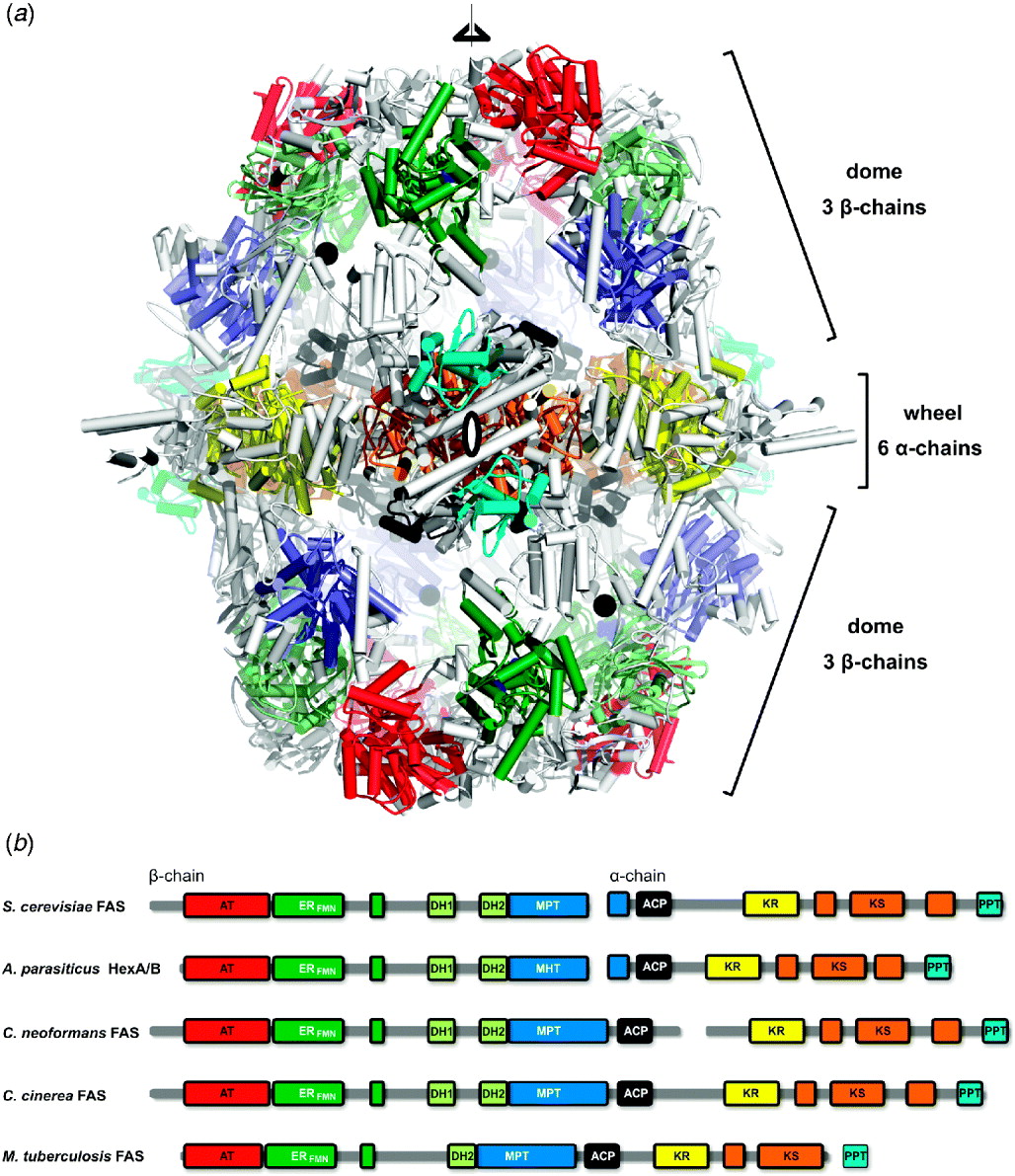
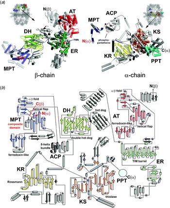
In the primary structure of fungal FAS, the catalytic domains are distributed over two polypeptide chains: The 230 kDa β-chain harbors the AT, ER, DH and most of the split MPT domain, whereas the remaining part of the MPT resides at the N-terminus of the 210 kDa α-chain, followed by ACP, KR, KS and the PPT (Fig. 8b). The assembled 2·6 MDa heterododecameric complex adopts a barrel-shaped structure with a central wheel formed by six α-chains, capped on each side by a dome of three β-chains (Fig. 8a) (Jenni et al. Reference Jenni, Leibundgut, Boehringer, Frick, Mikolasek and Ban2007; Leibundgut et al. Reference Leibundgut, Jenni, Frick and Ban2007; Lomakin et al. Reference Lomakin, Xiong and Steitz2007). The overall shape is remarkably similar to the one postulated by SAXS in 1969 (Pilz et al. Reference Pilz, Herbst, Kratky, Oesterhelt and Lynen1970) and the EM reconstructions (Hackenjos & Schramm, Reference Hackenjos and Schramm1987; Kolodziej et al. Reference Kolodziej, Penczek and Stoops1997), and the disposition of the α- and β-chains is in full agreement with the antibody cross-linking studies by the Lynen lab (Wieland et al. Reference Wieland, Siess, Renner, Verfurth and Lynen1978). The interior of the particle is divided by the central wheel into two equivalent reaction chambers, each harboring three full sets of catalytic sites and three double-tethered ACPs. Although the reaction chamber wall sequesters the ACPs from cytoplasmatic proteins and forms a micro-compartment within the cell, lateral holes allow the diffusion of substrates and products into and out of the chamber. The two reaction chambers are connected via additional openings in the central wheel, but the small size of these holes does not allow interactions between the ACPs from one chamber with catalytic domains in the other chamber. The PPT domain, which is not directly involved in the fatty acid elongation cycle, resides in the assembled complex at the periphery of the central wheel, outside both reaction chambers.
Structural organization of fungal FAS. (a) Crystal structure of yeast FAS at 3·1 Å resolution, colored by domains as indicated in (b), less well-conserved linking regions are shown in gray. The central wheel comprises the dimeric KS and KR domains and the peripheral PPT, while the β-chain domes contain the AT, MPT, ER and DH domains. The ACP attachment points are indicated by black spheres. The positions of the three- and one of the 2-fold symmetry axes are indicated. (b) Sequence comparison of FAS from various fungi. The presence of single-chain FAS in mycobacteria and basidiomycetes, such as Coprinopsis cinerea, indicates that the two-chain FAS occurring in most ascomycetes, such as Saccharomyces cerevisiae, are a result of gene splitting. The split occurs in various positions, but never within the linkers of the ACP, where it would conflict with double tethering.

Fungal FAS invests ~50% of the entire polypeptide chain into additional non-catalytic segments, either inserted into or between the catalytic core domains (Figs 8a and 9). These additional parts specifically occur in fungal FAS and have no counterparts in related systems. They build up a complicated scaffolding matrix into which the catalytic enzymes are embedded, and organize the α- and β-chains into the heterododecameric quaternary structure. Although these extensions are not directly involved in catalysis, they precisely define the topology and orientations of the catalytic domains within the reaction chambers.
Structures of isolated α- and β-chains from fungal FAS and the topology of catalytic domains. (a) The β-chain is formed by consecutive globular domains, whereas the α-chain adopts a highly intertwined structure with numerous insertions into the KS domain and a complex extension of the KR, which together form the rigid scaffold of the central wheel. The catalytic domains are shown in different colors, expansion segments or additional structural domains are depicted in gray. Note that the MPT (blue) is formed by both chains. The C-terminus of the β-chain and the N-terminus of the α-chain (highlighted in red) are only a few Å apart in the assembled FAS complex. The flexible linkers flanking the ACP domain, which are not visible in the structure, are indicated with dashed lines. (b) The topology diagram shows the folds of the catalytic domains (in color) and additional parts (gray) of one α- and β-chain. The DH domain (bright green) consists of a double-hotdog fold closely resembling the hydratase fold from the β-oxidation pathway (Koski et al. Reference Koski, Haapalainen, Hiltunen and Glumoff2004, Reference Koski, Haapalainen, Hiltunen and Glumoff2005), with a third structural hotdog fold inserted between the two catalytic halves. MPT (blue) and AT (red) share a similar fold, but contain different expansion segments. The highly complex diagram would look similar in ‘single-chain FASs’, except that in the MPT, both termini (highlighted in red) would be connected via a few additional amino acid residues (Figure kindly provided by S. Jenni).

An inspection of an isolated β- and α-chain reveals that the β-chain is roughly organized into globular catalytic and structural domains, whereas the architecture of the α-chain is much more intricate, with many insertions and extensions that together with neighboring α-chains result in the highly intertwined structure of the central wheel (Fig. 9).
In the context of the heterododecameric chain organization, it is noteworthy that the splitting of FAS into β- and α-chains, which are encoded by genes located on different chromosomes, is typical for ascomycetes, whereas basidiomycetes contain ‘single-chain’ FASs (Fig. 8b). In all available fungal FAS structures, the C-terminus of each β-chain is located very close to the N-terminus of an α-chain (Fig. 9b), and inspection of the intervening amino acid sequence in single-chain FASs reveals that both chains are linked only via a few additional residues. This would lead to a non-interrupted MPT domain and implies that the architecture of these homohexameric FASs would be similar to the structures of fungal FASs reviewed above. In the fungus Cryptococcus neoformans, chain splitting even occurs at a different location, outside any catalytic domain. These observations indicate that the α/β-chain organization is the result of a gene splitting event from an ancient single-chain FAS precursor that occurred during evolution. As the evolution of multifunctional FASs likely occurred through gene fusion events, the splitting into two chains most likely occurred at a later stage representing an evolution into the opposite direction. Finally, at least two ‘minimal versions’ of fungal-type FASs also exist: The specialized secondary metabolism hexanoate synthase (HexAB) complex, which is found in several filamentous fungi and synthesizes the aflatoxin precursor hexanoic acid, is organized into α- and β-chains, but lacks several expansion segments found at the top and the periphery of the FAS particle (Fig. 8b) (Brown et al. Reference Brown, Adams and Keller1996; Crawford et al. Reference Crawford, Vagstad, Ehrlich, Udwary and Townsend2008; Woloshuk & Prieto, Reference Woloshuk and Prieto1998). Further reduction is observed in the single-chain type I FAS of mycobacteria, which is involved in the biosynthesis of mycolic acids, major components of the bacterial cell wall. It not only lacks many of the structural domains and expansion segments but also the C-terminal PPT domain, which in this case is encoded by a separate gene located immediately downstream of the fas gene and obviously can act in trans (Fig. 8) (Chopra et al. Reference Chopra, Singh, Sati, Ranganathan and Sharma2002; Dym et al. Reference Dym, Albeck, Peleg, Schwarz, Shakked, Burstein and Zimhony2009; Schweizer & Hofmann, Reference Schweizer and Hofmann2004).
3.5 Active sites, linkers and substrate shuttling in fungal FAS
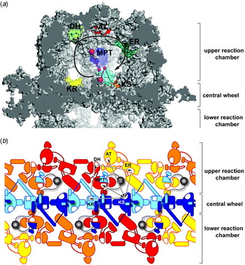
The ACP of fungal FAS forms an integral part of the multienzyme and is covalently attached to the complex via two flanking linkers, which could not be visualized in the crystal structures due to their flexibility (Figs 8 and 9a). The N-terminus of ACP is anchored peripherally to the reaction chamber wall, whereas the C-terminus is linked to the middle of the central wheel. The N-terminal linker has a high proline and alanine content, which likely increases its degree of rigidity (Perham, Reference Perham1991, Reference Perham2000; Radford et al. Reference Radford, Laue, Perham, Martin and Appella1989). This probably reduces the risk of entanglement of the three ACP domains in each reaction chamber and limits the free diffusion of each ACP to the closest set of active sites. The active site clefts of the enzymatic domains participating in the fatty acid elongation cycle all point towards the interior of the reaction chamber, optimally oriented to interact with the ACP, and are arranged in a circular path around the attachment sites in the order of the reaction sequence (Fig. 10a). This active site topology is optimally suited for efficient catalysis by minimizing the diffusion distances for substrate shuttling between the active sites during the reaction cycle. Interestingly, in fungal FAS the distance between the catalytic sites of MPT and KS is considerably shorter than the KS–AT distance, reflecting the usage frequency of primer and elongation substrates: for the synthesis of a full-length fatty acid, acetyl-ACP is only needed once, whereas malonyl-ACP is the substrate in every reaction cycle.
Topological distribution of one full set of catalytic sites in the reaction chamber. (a) The section through the FAS particle shows one of the three full sets of catalytic sites per reaction chamber. The catalytic clefts are arranged in a circular manner around the central and peripheral ACP anchor points (shown as large magenta spheres) in the order of the reaction cycle. The free diffusion of the ACP (bright blue), which in the view is stalled at the KS (orange), is restricted by the flanking linkers (dashed lines, anchor points on ACP as small spheres, magenta). The diffusion distance to the AT (red) is considerably larger than to the centrally arranged MPT, reflecting the frequency of malonyl and acetyl substrate use. (b) Planar map projection of the interior of the fungal FAS particle, showing schematically the chain distribution in the complex. The six α-chains (bright and dark blue) form the central wheel, capped by three β-chains on each side (orange, yellow and red), which form the domes. Inspection of one full set of catalytic centers (connected by arrows) shows that the catalytic domains originate from two α- and two β-chains and that the ACP of one α-chain cannot interact with the KS of the same chain.

Considering the possibilities of an interaction between ACP and KS, it is evident from the structure that the ACP from one α-chain cannot interact with the KS from the same chain and consequently, at least two α-chains are required for catalysis (Fig. 10b). This corroborates the finding of the ACP–KS-specific dibromo-propanone cross-linking studies by Wakil et al. (Stoops & Wakil, Reference Stoops and Wakil1980), which revealed an oligomerization of α-chains upon treatment with the reactive compound. In addition, the shortest path through the reaction cycle shows that the domains located on the β-chains also originate from two different β-chains for each set of catalytic sites, although the existence of alternative reaction paths, which would result in considerably longer ACP diffusion routes, cannot be entirely excluded (Fig. 10b).
The fold of ACP and the linker attachment sites on the ACP surface could be visualized in yeast FAS, where ACP was found stalled close to the catalytic cleft of the KS domain (Leibundgut et al. Reference Leibundgut, Jenni, Frick and Ban2007). In contrast to plant, bacterial and animal ACPs that fold into ~9 kDa 4-helix bundles, the fungal ACP is almost twice as large as it contains four additional helices (Bunkoczi et al. Reference Bunkoczi, Pasta, Joshi, Wu, Kavanagh, Smith and Oppermann2007; Roujeinikova et al. Reference Roujeinikova, Simon, Gilroy, Rice, Rafferty and Slabas2007; Zornetzer et al. Reference Zornetzer, Fox and Markley2006). The N- and C-terminal linker attachment sites are located next to each other on the back side of ACP, whereas the phosphopantetheine prosthetic group is linked on the opposite side of the globular domain, which likely minimizes the interference between the linkers and the flexible arm. In an extended conformation of the phosphopantetheine arm, as exemplified by the KS-bound ACP, the distance between the sulfhydryl group of the prosthethic group and the linker attachment site on ACP is ~55 Å, whereas the distances to all other catalytic sites are in the range of 60–80 Å. In order to follow the circular path along the reaction cycle, ACP would therefore not have to move along the entire path between the active sites, but could in principle compensate for the large distances by rotation around a pivot point with a rather moderate translation. However, with the exception of the KS, it is currently unclear how the ACP interacts with other domains for delivering the substrates into their catalytic clefts by its phosphopantetheine arm.
A more detailed analysis of the KS–ACP interaction in yeast FAS demonstrates both the similarities with and differences to the dissociated FAS systems (Leibundgut et al. Reference Leibundgut, Jenni, Frick and Ban2007). Genetic, crystallographic and nuclear magnetic resonance (NMR) spectroscopic studies as well as docking models of type II ACPs reveal that the small, acidic ACP contacts the catalytic domains with a highly conserved ‘recognition’ helix, which is located immediately downstream of the loop that contains the serine with the attached prosthetic group (Parris et al. Reference Parris, Lin, Tam, Mathew, Hixon, Stahl, Fritz, Seehra and Somers2000; Rafi et al. Reference Rafi, Novichenok, Kolappan, Zhang, Stratton, Rawat, Kisker, Simmerling and Tonge2006; Zhang et al. Reference Zhang, Rao, Heath, Price, Olson, Rock and White2001, Reference Zhang, Wu, Zheng and Rock2003). The corresponding ACP helix, which is highly conserved among fungi and shares the highest sequence homology with the type II counterpart, is also involved in the yeast ACP–KS contact, although several residues directly adjacent to the phosphopantetheinyl-serine moiety differ between the type II and the fungal ACPs. A second binding area located at the base of the four extra helices is in contact with a region of the central wheel that corresponds to a fungal-specific insertion into the KS domain (Leibundgut et al. Reference Leibundgut, Jenni, Frick and Ban2007). The ACP–KS interface is characterized by a high degree of amino acid conservation and a complementary charge distribution, with the KS side being strongly acidic and the ACP surface predominantly basic (Leibundgut et al. Reference Leibundgut, Jenni, Frick and Ban2007). The observation that KS expansion segments of the fungal FAS complex are involved in contacting the ACP raises the question whether the scaffold, into which the other catalytic domains are embedded, evolved such that it assists in orienting the ACP optimally towards their catalytic clefts in a similar manner. Stable, high affinity ACP binding to any of the catalytic domains contradicts the requirement for transiency in substrate shuttling. Still, low-affinity guiding interactions might increase the overall efficiency of the reaction. In case of the ACP stalled at the KS, the preferential binding might reflect the need for binding twice to the KS domain during each reaction cycle (Lomakin et al. Reference Lomakin, Xiong and Steitz2007).
In the ACP stalled at the KS, the phosphopantetheine arm is in an extended conformation, allowing it to directly reach the catalytic center of the KS with its thiol group positioned for substrate delivery. Several structures of type II ACPs with bound acyl chains of different length showed that the insoluble fatty acid was buried deep within a hydrophobic pocket of the ACP, which might represent a transport form for substrate shuttling between the individual enzymes (Roujeinikova et al. Reference Roujeinikova, Simon, Gilroy, Rice, Rafferty and Slabas2007; Zornetzer et al. Reference Zornetzer, Fox and Markley2006). Based on these observations, Leibundgut et al. proposed a switchblade-like mechanism, in which the acyl chain remains buried within the fungal ACP during inter-domain-shuttling in a similar manner as observed in type II FAS, whereas it is flipped out into the hydrophobic reaction pockets for catalysis (Leibundgut et al. Reference Leibundgut, Jenni, Frick and Ban2007). The presence of such dual conformations of fungal FAS ACP, or the possibility for further conformational states as previously observed for the related peptidyl carrier protein in non-ribosomal peptide synthase systems (Koglin et al. Reference Koglin, Mofid, Lohr, Schafer, Rogov, Blum, Mittag, Marahiel, Bernhard and Dotsch2006), remains to be confirmed experimentally.
The PPT domain, which transforms apo- to holo-ACP by transferring the phosphopantetheine moiety from CoA to ACP, comprises an integral part of the fungal FAS α-chain (Fig. 5b) (Fichtlscherer et al. Reference Fichtlscherer, Wellein, Mittag and Schweizer2000). However, the PPT domain is not integrated into the reaction chamber wall like the other domains, which are directly involved in the fatty acid elongation cycle, but is found at the periphery of the central wheel, separated from the ACP (Johansson et al. Reference Johansson, Wiltschi, Kumari, Kessler, Vonrhein, Vonck, Oesterhelt and Grininger2008; Lomakin et al. Reference Lomakin, Xiong and Steitz2007). As each ACP needs to be modified only once during the assembly of the particle, such arrangement might be optimal to minimize the interference of this enzyme with the ACP motion during the reaction cycle, but poses the problem of how the ACP within the chamber can be activated at all, as the openings in the reaction chamber walls would be too small to allow passage of the PPT domain into the reaction chamber (Lomakin et al. Reference Lomakin, Xiong and Steitz2007). One possibility is that the fungal FAS auto-activates prior to the closure of the reaction chambers, during the assembly of the hexameric (single-chain FAS) or heterododecameric (double-chain FAS) complex.
All PPTs known so far are active either as trimers (bacteria) or pseudo-dimers (mammals), with the ACP bound between two PPT (pseudo-)subunits (Bunkoczi et al. Reference Bunkoczi, Pasta, Joshi, Wu, Kavanagh, Smith and Oppermann2007; Parris et al. Reference Parris, Lin, Tam, Mathew, Hixon, Stahl, Fritz, Seehra and Somers2000). Moreover, ACPs from both the fungal-like FASI of M. tuberculosis and the simultaneously present FAS type II system are activated by a trimeric ACP synthase (Dym et al. Reference Dym, Albeck, Peleg, Schwarz, Shakked, Burstein and Zimhony2009), which is encoded by an individual gene located immediately downstream of the FASI open reading frame. In contrast, the fungal PPT located in the FAS complex is monomeric, indicating that it may be in a non-productive state and that the fungal PPT would have to form at least a dimer in order to be functional (Lomakin et al. Reference Lomakin, Xiong and Steitz2007). In a very recently published high-resolution structure of the isolated yeast PPT domain, the fungal enzyme was indeed found to form trimers, very similar to the bacterial counterpart, and the necessity of multimerization for proper function was corroborated with an elegant series of complementation experiments (Johansson et al. Reference Johansson, Mulinacci, Koestler, Vollrath, Oesterhelt and Grininger2009). Interestingly, when isolated yeast ACP was mixed with purified α6β6-FAS complex, it was also phosphopantetheinylated. For activity, the PPT domains at the particle's periphery would have to form transient dimers or even trimers, which is only possible if they change their position relative to the FAS complex. Indeed, the binding site of the PPT domain observed in the crystal structures (Johansson et al. Reference Johansson, Wiltschi, Kumari, Kessler, Vonrhein, Vonck, Oesterhelt and Grininger2008, Reference Johansson, Mulinacci, Koestler, Vollrath, Oesterhelt and Grininger2009; Lomakin et al. Reference Lomakin, Xiong and Steitz2007) is only poorly conserved among fungal FASs, and the flexibility of the PPT domain is also reflected by the lower electron density levels observed for this domain in crystallographic and EM maps (Jenni et al. Reference Jenni, Leibundgut, Boehringer, Frick, Mikolasek and Ban2007; Lomakin et al. Reference Lomakin, Xiong and Steitz2007).
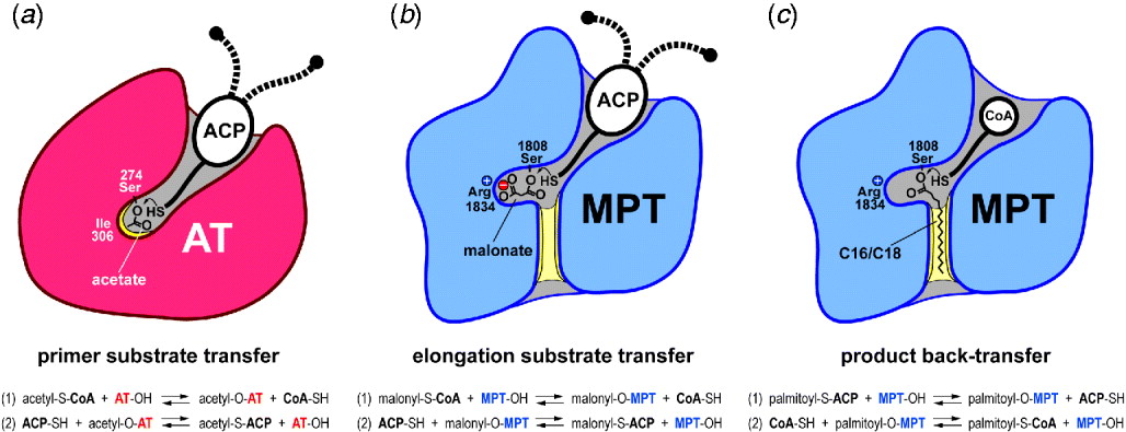
An intriguing aspect of the fungal fatty acid elongation reaction is how the AT and MPT enzymes specifically discriminate between their substrates and how the FAS complex determines the chain length of fatty acid products. Due to its dual role in elongation substrate transfer and final product release, the MPT is obviously an ideal candidate for chain-length regulation. The FAS transferases, AT and MPT, catalyze a reversible two-step ping–pong reaction: in the first step, they transfer the substrate from CoA to an active site serine group to form a covalent enzyme–substrate complex, and in the second reaction, the substrate is further trans-esterified to the reactive phosphopantetheine thiol group of ACP. In the crystal structure of bacterial MT in complex with malonyl-CoA, the distal, negatively charged carboxyl group of the malonyl moiety is held in place by a positively charged active site arginine via a bidentate salt bridge, while the proximal carboxyl moiety is esterified to the active site serine (Oefner et al. Reference Oefner, Schulz, D'Arcy and Dale2006). An inspection of the corresponding residues in the active site of fungal AT and MPT reveals that the MPT also contains this arginine, while the residue in the AT is a hydrophobic isoleucine, optimally suited for the recognition of the uncharged methyl moiety of the acetyl group, but not for the malonyl moiety (Fig. 11a, b) (Jenni et al. Reference Jenni, Leibundgut, Boehringer, Frick, Mikolasek and Ban2007; Lomakin et al. Reference Lomakin, Xiong and Steitz2007).
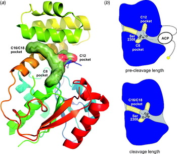
Substrate specificity of the acetyl and MPTs in fungal FAS (residues are numbered according to yeast FAS). (a) AT specifically recognizes the acetyl moiety with a closed reaction pocket containing a hydrophobic isoleucine. The AT transfers the primer substrate in a two-step reaction first from the phosphopantetheine moiety of CoA to its catalytic serine and in a second step to the prosthetic phosphopantetheine arm of ACP. (b) For elongation substrate transfer, the double-specific MPT recognizes the malonyl moiety via a bidentate salt bridge in its catalytic center, which in the two-step reaction mechanism is first bound to the catalytic serine of MPT and then transferred to ACP. (c) As soon as the fatty acid product has reached a chain length of C16 or longer, its saturated acyl chain binds to a hydrophobic cleft of the MPT, thereby preventing further binding of the elongation substrate malonyl-CoA until the mature fatty acid is back-transferred from ACP to CoA.
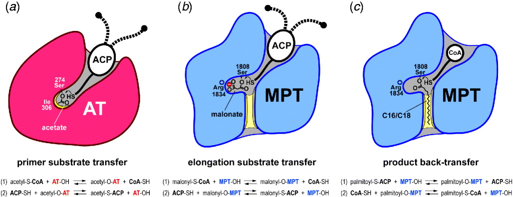
Based on the biochemical characterization of the yeast MPT, a model for the double specificity of fungal MPT and how it might regulate the reaction cycle had been proposed in the late 1970s by the Lynen lab (Engeser et al. Reference Engeser, Hubner, Straub and Lynen1979). Having the crystal structure of MPT at hand, this model now can be readily verified (Fig. 11b, c): inspection of the fungal MPT shows a deep, mainly hydrophobic crevice stretching toward the back side of the domain, which is absent in the AT domain and appears optimally suited for binding the hydrophobic C16 tail of palmitate (Jenni et al. Reference Jenni, Leibundgut, Boehringer, Frick, Mikolasek and Ban2007; Lomakin et al. Reference Lomakin, Xiong and Steitz2007). As long as the growing acyl chain has not yet reached its full-length, malonyl-CoA preferentially binds to the MPT, thereby blocking the active site and preventing the premature release of the product. As soon as a chain length of C16 is reached, the binding of the palmitoyl-ACP to the MPT cleft will be strong enough to displace the malonyl and allow the back-transfer of the acyl group to CoA and the subsequent release of the palmitoyl-CoA product. The binding of the palmitoyl product to the active site of MPT also coordinates the MPT-dependent elongation and AT-dependent priming reactions by facilitating the uptake of an acetyl moiety at the moment of termination: While malonyl uptake is prevented due to the blocked MPT active site, ACP can be charged with a new primer at the AT (Engeser et al. Reference Engeser, Hubner, Straub and Lynen1979). It should still be noted that the MPT does not measure the length of the acyl chain in a strict sense: The MPT is able to transfer saturated acyl chains of different chain lengths readily if they are offered as CoA-bound substrates, and these acyl chains can even be fed into the reaction cycle as efficient primers (Pirson et al. Reference Pirson, Schuhmann and Lynen1973; Schweizer et al. Reference Schweizer, Lerch, Kroeplin-Rueff and Lynen1970). In addition, if the supply of substrates is limited, the formation of saturated acyl-CoA products with shorter chain lengths is promoted in the yeast FAS complex (Sumper et al. Reference Sumper, Oesterhelt, Riepertinger and Lynen1969). Thus, the chain-length determination in fungal FAS should rather be considered as an intricate equilibrium of substrates and products that might be influenced also by other domains, such as the capacity of ACP to efficiently shuttle very long acyl chains or that of the KS to use long acyl chains as primers, which might also impose an additional upper limit to the maximum chain-length that can be achieved.
4. Animal FAS
4.1 Domain composition and reaction cycle
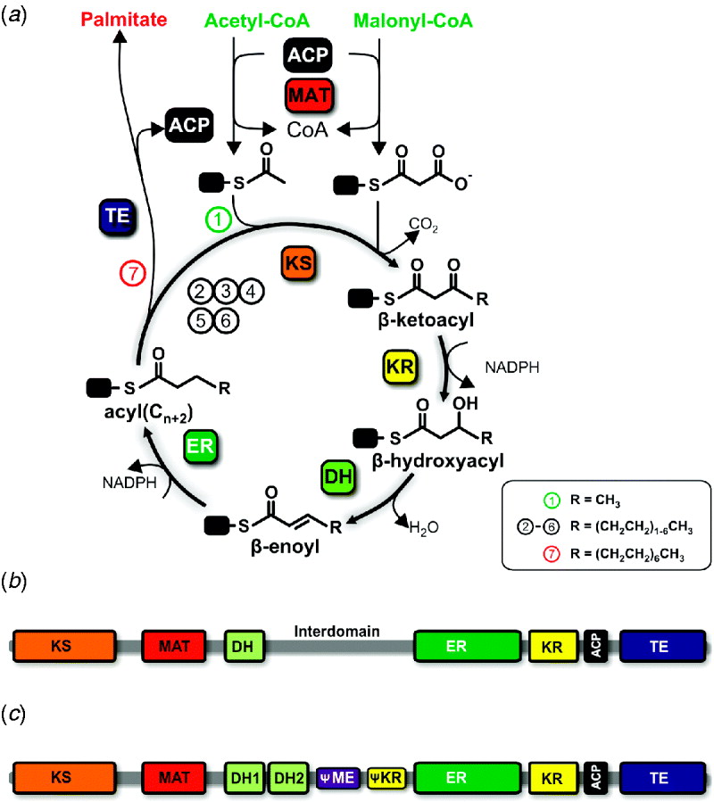
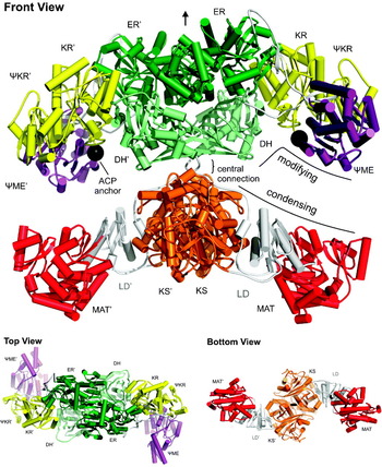
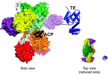
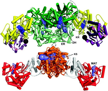
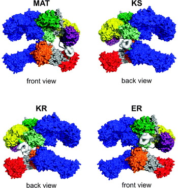
The animal FAS catalyzes the biosynthesis of fatty acids through a variation of the common cyclic reaction scheme utilized by the bacterial and fungal FAS systems (Fig. 12a). A bifunctional acyl transferase domain, the malonyl-acetyl-transferase (MAT), first loads an acetyl-unit from acetyl-CoA onto the ACP, which transfers the starter acetyl group onto the active site cysteine of the KS. The ACP is then charged with a malonyl-moiety from malonyl-CoA again by the MAT domain. In the KS active site, the malonyl group is decarboxylated to form a reactive carbanion, which carries out a nucleophilic attack on the carboxyl group of the KS-bound acetyl moiety. The resulting ACP-tethered β-ketoacyl intermediate, acetoacetyl-ACP, is further modified at its β-carbon position by reduction to a β-hydroxyacyl moiety through the NADPH-dependent KR, water elimination by the DH to a β-enoyl intermediate and a second reduction by the NADPH-dependent ER yielding a fully saturated fatty acid elongated by a two-carbon unit, butanoyl-ACP. This product enters the cycle again as a new starter substrate and the cycle continues until a length of C16 is reached and the final product palmitate is released as a free fatty acid after cleavage from the ACP by the thioesterase (TE) domain.
Domain composition and reaction cycle of animal FAS. (a) Catalytic reaction cycle of animal FAS, see text for details. (b) Linear domain arrangement of animal FAS based on sequence and biochemical analysis of animal FAS before structure determination. (c) Linear domain arrangement of animal FAS based on the crystal structure of porcine FAS.

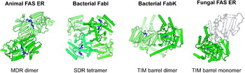
The key differences to the fungal system are: (i) the use of a single acyl transferase for loading both the substrates, (ii) the existence of a separate TE for product release as free fatty acids and (iii) the fold and mechanism of the ER domain, which is not FMN-dependent in animal FAS and has, based on sequence analysis, a classical Rossmann-fold nucleotide-binding domain (Schweizer & Hofmann, Reference Schweizer and Hofmann2004; Smith et al. Reference Smith, Witkowski and Joshi2003). Further, animal FAS does not encompass a PPT domain for cofactor attachment. Such functionality is provided in trans by a separate enzyme, the holo ACP synthase. This enzyme is responsible for cofactor loading in all three mammalian ACP-based systems, the mitochondrial ACP as part of a bacterial type II fatty acid synthesis system, the cytosolic FAS multienzyme and the aminoadipate semialdehyde dehydrogenase. The animal holo ACP synthase most closely resembles the pseudo-dimeric Bacillus subtilis Sfp PPT regarding its domain structure, but differs with respect to the details of its catalytic mechanism and ACP recognition (Bunkoczi et al. Reference Bunkoczi, Pasta, Joshi, Wu, Kavanagh, Smith and Oppermann2007).
At the sequence level, the order of domains in animal FAS differs from the fungal system (Fig. 12b). The N-terminal KS domain is followed first by an extended linker region, then by the MAT domain and another linker region, leading into the DH domain. Based on sequence comparison and mutational analysis of the active site histidine, the DH domain was located approximately to residues 830 to 970 (Chirala & Wakil, Reference Chirala and Wakil2004; Chirala et al. Reference Chirala, Huang, Jayakumar, Sakai and Wakil1997; Joshi & Smith, Reference Joshi and Smith1993b; Smith et al. Reference Smith, Witkowski and Joshi2003). The central portion of the sequence, encompassing approximately residues 1000 to 1500, has no assigned catalytic function and is less well conserved than the enzymatic domain regions, but has been implicated in the dimerization of animal FAS (Chirala et al. Reference Chirala, Jayakumar, Gu and Wakil2001; Smith et al. Reference Smith, Witkowski and Joshi2003; Witkowski et al. Reference Witkowski, Rangan, Randhawa, Amy and Smith1991). Following this so-called ‘inter-domain’, are the two reductase domains, first the ER, and then the KR. Both domains are characterized by a typical nucleotide-binding fold but lack the Zn-binding sites observed in related alcohol dehydrogenases and contain specific substrate-binding extensions to the core fold (Witkowski et al. Reference Witkowski, Rangan, Randhawa, Amy and Smith1991). The ACP domain is located downstream of the KR domain. Based on the NMR structure of the rat FAS ACP domain and the crystal structure of the human FAS ACP domain in complex with the holo ACP synthase, ACP forms a typical four-helix bundle, with the serine for cofactor attachment preceding the second helix of the bundle (Bunkoczi et al. Reference Bunkoczi, Pasta, Joshi, Wu, Kavanagh, Smith and Oppermann2007; Ploskon et al. Reference Ploskon, Arthur, Evans, Williams, Crosby, Simpson and Crump2008).
The C-terminal TE domain is composed of two subdomains, a typical α/β-hydrolase fold containing the active site residues and an α-helical domain, which forms the binding pocket for long acyl chain substrates (Fig. 13a) (Chakravarty et al. Reference Chakravarty, Gu, Chirala, Wakil and Quiocho2004; Pemble et al. Reference Pemble, Johnson, Kridel and Lowther2007). The substrate specificity of the TE domain for C16/C18 fatty acids is the most important factor for the determination of product chain length in animal FAS and was also observed for the isolated domain (Lin & Smith, Reference Lin and Smith1978). These findings were finally rationalized by the observation of three distinct substrate-binding pockets in the cocrystal structures of the isolated TE domain with the inhibitor orlistat, which was found as a covalent acyl-enzyme intermediate in one and as a hydrolyzed product in the other TE molecule in the ASU (Pemble et al. Reference Pemble, Johnson, Kridel and Lowther2007). The binding pockets appear to be specific for either short chain, medium chain or long chain (C16 or C18) acyl chains, and only the binding of the acyl chain into the long chain pocket positions the thioester bond for productive catalysis to occur (Fig. 13b). The TE domain is tethered to the ACP domain via a 20–30-residue-linking region with lower sequence conservation. Deletion of up to half of this linking region has no effect on the mobility of the TE domain or the overall catalytic efficiency of FAS. Lengthening of the linker increases TE mobility, but again without any effect on the overall reaction. However, shortening the linker by more than 10 residues reduces its mobility, shifts the FAS product spectrum to longer acyl chains and reduces the overall activity (Joshi et al. Reference Joshi, Witkowski, Berman, Zhang and Smith2005). This effect is most likely a consequence of the reduced flexibility of the short-linked TE domain, resulting in limited access to and slower release of ACP-tethered substrates. Together, these results indicate that the connection between the ACP and the TE domain is mediated by a non-structured flexible linker.
Chain-length determination in animal FAS by the TE domain. (a) Crystal structure of the TE domain of human FAS (rainbow coloring from N- to C-terminus) in complex with a hydrolysis product of the inhibitor Orlistat (Pemble et al. Reference Pemble, Johnson, Kridel and Lowther2007), which occupies three pockets with a suggested specificity for short, medium and long acyl chains. The C16/C18 pocket is mainly formed by the α-helical substrate-binding domain (upper part, light green). (b) Schematic depiction of binding of medium-chain length acyl-ACP intermediates into a pocket not allowing cleavage (upper panel). Only the binding of long chain acyl moieties into the cognate long chain acyl pocket allows productive positioning of the acyl-ACP thioester bond and cleavage from ACP (lower panel).

4.2 Purification and crystallization of animal FAS
The animal FAS multienzyme has traditionally been natively purified from a variety of animal tissues (Arslanian & Wakil, Reference Arslanian and Wakil1975; Dils & Carey, Reference Dils and Carey1975; Jenik & Porter, Reference Jenik and Porter1981; Kawaguchi et al. Reference Kawaguchi, Tomoda, Okuda and Omura1981; Kim et al. Reference Kim, Neudahl and Deal1981; Kolattukudy et al. Reference Kolattukudy, Poulose and Buckner1981; Kumar & Dodds, Reference Kumar and Dodds1981; Muesing & Porter, Reference Muesing and Porter1975; Roncari, Reference Roncari1981; Smith & Abraham, Reference Smith and Abraham1975). Particularly high yields were observed from liver (Arslanian & Wakil, Reference Arslanian and Wakil1975; Kim et al. Reference Kim, Neudahl and Deal1981; Muesing & Porter, Reference Muesing and Porter1975; Roncari, Reference Roncari1981), often from animals fed on a carbohydrate-based diet, and from fat producing glands, including the lactating mammary gland (Kumar & Dodds, Reference Kumar and Dodds1981; Smith & Abraham, Reference Smith and Abraham1975) and the uropygial gland of birds (Kolattukudy et al. Reference Kolattukudy, Poulose and Buckner1981). High yields of purified human FAS were also obtained from a mammary epithelial cell line (Thompson et al. Reference Thompson, Stern and Smith1981). After the determination of cDNA sequences, animal FAS was expressed recombinantly with modest yields in Escherichia coli (Jayakumar et al. Reference Jayakumar, Huang, Raetz, Chirala and Wakil1996), but with high yields up to 20% of the total soluble cytoplasmic proteins in insect cell culture (Joshi & Smith, Reference Joshi and Smith1993a).
For structure determination, Maier et al. purified native FAS from animal tissues by fractionated ammonium sulfate precipitation, ion exchange and size exclusion chromatography (Maier et al. Reference Maier, Jenni and Ban2006). As the expression of FAS is very low in animal tissues (Weiss et al. Reference Weiss, Hoffmann, Schreiber, Andres, Fuchs, Korber and Kolb1986) and large amounts of tissue are not available from animals fed on a specific diet, the lactating mammary gland tissue was chosen as a native source of overexpression, based on earlier reports (Kumar & Dodds, Reference Kumar and Dodds1981; Smith & Abraham, Reference Smith and Abraham1975) and mRNA expression database mining. The starting material was obtained from a local abattoir and immediately frozen in liquid nitrogen and stored at −80°C to avoid proteolytic damage to the animal FAS. The purification procedure was established for one source organism using western blot detection of FAS with a commercially available antibody and by employing a specific assay for the detection of the KR domain partial activity (Ullman et al. Reference Ullman, Harding and White1978). An initial ammonium sulfate fractionation proved effective for the rapid removal of most cellular proteolytic activities. The combination of native overexpression in the starting material with the use of high-resolution preparative scale anion exchange and gel filtration chromatography yielded highly purified, monodisperse animal FAS (Maier et al. Reference Maier, Jenni and Ban2006).
While fungal FAS is a highly symmetric, mostly rigid particle, animal FAS is a dynamic assembly that exists in several conformations, often without the 2-fold symmetry expected for the dimeric molecule (Kitamoto et al. Reference Kitamoto, Nishigai, Sasaki and Ikai1988). Therefore, despite its smaller size, animal FAS appears as the more difficult target for crystallization than fungal FAS. Initial crystallization screening was thus carried out by Maier et al. (Reference Maier, Jenni and Ban2006) in a robotic nanoliter setup using commercial and custom grid and factorial screens for FAS purified from various animal sources, using more than 3000 conditions per sample. A single initial crystallization condition was identified at neutral pH for porcine FAS using medium length PEG as a precipitant. Crystals belong to the monoclinic space group P21 with unit cell dimensions of a=96 Å, b=245 Å, c=134 Å and β=101°, yielding a theoretical solvent content of 57%. In spite of extensive optimization of crystallization conditions, the largest crystals obtained were thin plates and only 25 μm thick (Maier et al. Reference Maier, Leibundgut and Ban2008).
4.3 Phasing and structure determination
As it was the case for the fungal FAS, the complexity of animal FAS precluded the use of molecular replacement as a method for structure determination, although template structures for most of the domains of animal FAS were known at atomic resolution. Even the largest of the known domains, the KS dimer, would correspond to less than 20% of the total animal FAS, and molecular replacement searches with several closely related folds present in the animal FAS, e.g. the KR and ER Rossmann-folds, would be prone to miss-assignment. Therefore, the method of choice for solving the phase problem for animal FAS was to obtain model-bias free experimental phases based on heavy atom derivatives. In this case, as it was the case with the fungal FAS, selenomethionine derivatization was not an option, since the crystals were produced from the natively purified protein. Strong diffraction was only observed at resolutions where the scattering of single heavy atoms is usually not sufficient for locating their sites. Therefore large tungstate clusters, such as (W12O40) were soaked into the crystals and localized using their anomalous scattering contribution by direct methods as implemented in SHELXD. The resulting 9 Å resolution phases provided a first low-resolution electron density map of animal FAS (Maier et al. Reference Maier, Jenni and Ban2006). However, tungstate cluster derivatized crystals suffered from severe non-isomorphism to native crystals. Once larger crystals up to 15 μm thickness and diffracting up to around 4 Å resolution were obtained, derivatization with single heavy atoms became feasible. In spite of the extreme sensitivity of the crystals to heavy atom derivatization, it was ultimately possible to identify uranyl nitrate as a suitable derivative with uncompromised diffraction. Binding sites of uranyl nitrate were located ab initio by direct methods and confirmed by cross-phasing through Fourier map calculation based on phases initially obtained from a tungstate cluster derivative. Phases obtained from the uranyl nitrate and a weaker chloroplatinate derivative were extended to 4·2 Å resolution and improved by solvent flipping density modification under optimization of the nominal solvent content. The resulting maps were used to identify secondary structure elements and the folds of catalytic domains. Operators describing the observed 2-fold domain-wise NCS were obtained from the placed domains and used to reiterate density modification, which yielded substantially improved maps. Due to the limited resolution, Maier et al. interpreted the map at ~4·5 Å by rigid-body fitting of template structures based on the unambiguous identification of secondary structural elements in the density maps, without further crystallographic refinement (Fig. 14) (Maier et al. Reference Maier, Jenni and Ban2006). This interpretation revealed architectural features of the animal FAS in terms of positioning of the catalytic domains and the orientation of their active sites, with additional parts of the molecule clearly visible as remaining un-interpreted regions of electron density.
Experimental electron density maps of animal FAS. Experimentally phased crystallographic electron density maps of porcine FAS in the DH (upper panel) and ER (lower panel) region. The left column shows the experimental density at 4·5 Å resolution (Maier et al. Reference Maier, Jenni and Ban2006) used for the rigid-body fitting of template domains, while the right panel depicts the experimental density after phase extension to 3·2 Å resolution (Maier et al. Reference Maier, Leibundgut and Ban2008) with alternative views of the same regions. This map was used for initial atomic model building of porcine FAS.

Further improvement of crystal growth (Fig. 15a) and optimization of crystal stabilization that included temperature shifts prior to crystal freezing was required to obtain data to 3·2 Å resolution necessary for building of an atomic model and refinement (Maier et al. Reference Maier, Leibundgut and Ban2008). Furthermore, due to the small size and radiation sensitivity of crystals even when frozen, a multi-crystal data collection strategy was required to obtain a complete dataset: crystals were translated multiple times collecting about 5–10° of rotation per position, and data from several isomorphous crystals were scaled together. The diffraction of animal FAS crystals was weak at high resolution and a reduction of background was critical for obtaining the best possible data quality. For data collection, the crystals were mounted free-standing without surrounding solvent to reduce the background from solvent scatter (Fig. 15b). Additionally, an open flow helium cryostat was used to cool the crystal to 10 K during data collection, which mitigated radiation damage by approximately 30% compared to data collection at 100 K using a nitrogen cryostream (Fig. 15c) (Chinte et al. Reference Chinte, Shah, Chen, Pinkerton, Schall and Hanson2007; Meents et al. Reference Meents, Wagner, Schneider, Pradervand, Pohl and Schulze-Briese2007). This procedure also reduced the air or nitrogen scattering of X-rays since the direct beam path between the collimator and the beamstop was flooded with helium resulting in an approximately 3-fold reduction of the background. Using a complete and redundant 3·2 Å native dataset obtained in this way, it was possible to extend experimental phases to the full resolution of the data by density modification using domain-wise NCS averaging and statistical density modification (Fig. 14) (Cowtan, Reference Cowtan2002).
Strategies for high-resolution data collection for animal FAS crystals. (a) Crystals of up to 0·7 mm in length (mounted in nylon loop for data collection) were obtained through a fine-screening of crystallization conditions. (b) Illustration of the data collection strategy: the crystals are exposed at multiple, non-overlapping positions to reduce radiation damage. Exposure of free-standing parts of the crystals not surrounded by excess liquid results in the absence of typical rings of solvent scattering from diffraction patterns. (c) Data collection using an open flow helium cryostat to flood the full path of the direct beam with helium. At temperatures around 10 K, radiation damage is mitigated, and the background from scattering of the direct beam is reduced in a helium atmosphere.

4.4 Overall architecture and linkers
The homodimeric animal FAS adopts an extended X-shaped conformation, with dimensions of approximately 200×170×110 Å3 (Fig. 16). It is segregated into two parts, a lower or condensing part with the KS and the MAT domains and an upper or modifying part, containing all domains responsible for β-carbon modification. The two regions are centrally connected and define two lateral clefts (Maier et al. Reference Maier, Jenni and Ban2006, Reference Maier, Leibundgut and Ban2008).
Structural overview of animal FAS. The crystal structure of porcine FAS is shown in cartoon representation colored by domains as in Fig. 12. The dimeric enzyme consists of two centrally connected parts, a lower ‘condensing’ part containing the KS and MAT domain and an upper ‘modifying’ part containing the β-carbon modification domains. The anchor points for the non-resolved C-terminal ACP/TE domains are shown as black spheres. The top and bottom view (lower panels) demonstrate the S-shape of the two parts, the ψME domain is protruding from the main body of FAS. The position of the pseudo-2-fold symmetry axis is indicated by arrows/ellipsoids.

The arrangement of domains in the 3D structure does not follow their linear order at the sequence level (Figs 12 and 16). The N-terminal KS domain dimerizes in the center of the condensing part. The polypeptide forms a linking domain and continues into the laterally attached MAT domains. The linker from the MAT to the DH domain contributes a considerable part to the KS–MAT-linking domain and further wraps around the KS domain up to the 2-fold axis of symmetry in the center of the molecule. From here it directly leads into the central DH domain, before continuing through an extended linker to the periphery of the upper half into a non-catalytic domain, which is referred to as pseudo-methyltransferase (ψME) , because it esembles a particular class of methyltransferases. The following domain in sequence represents a reduced, inactive form of a ketoreductase domain, and thus is termed as pseudo-KR (ψKR). It is located next to the ψME at the periphery of the condensing moiety. The second hotdog fold of the DH domain together with the two non-catalytic domains represents the non-catalytic region of unknown function, formerly known as the ‘inter-domain’ (Fig. 12c). From the ψKR, the chain first leads into the central ER domain, which contributes to dimerization of the molecule, before turning outwards again into the KR domain. The C-terminal ACP and TE domains are flexibly attached (Joshi et al. Reference Joshi, Witkowski, Berman, Zhang and Smith2005) and not resolved in the X-ray crystal structure. They are tethered to an anchor at the C-terminus of the KR domain, centrally located in the upper lids of the lateral clefts.
Dimerization is mainly mediated through the homophilic interactions of the KS domain in the lower and the ER domain in the upper part, together contributing about 80% of the dimerization interface of 5400 Å2 (Maier et al. Reference Maier, Leibundgut and Ban2008). The inter-subunit interactions of these domains closely resemble the oligomerization modes of their monofunctional homologues (Olsen et al. Reference Olsen, Kadziola, Von Wettstein-Knowles, Siggaard-Andersen and Larsen2001; Shimomura et al. Reference Shimomura, Kakuta and Fukuyama2003). Their respective contact sites directly involve the core catalytic parts, not just additional insertions, and are crucial for the integrity and catalytic activity of both domains. Core β-strands of the KS and ER catalytic domains join across the dimerization interface to form inter-subunit continuous β-sheets. Additional weak contributions arise from interactions of the two DH domains and the linkers leading into the DH domains. However, their interface is considerably smaller and could probably not even provide a stable dimerization of a hypothetical isolated DH domain.
The animal FAS, in contrast to the fungal multienzyme, has no scaffold that tightly embeds the core enzymatic domains (Maier et al. Reference Maier, Leibundgut and Ban2008). While the fungal FAS invests about 50% of its total length into forming this scaffold, only 9% of the total sequence are present in the form of linker regions in animal FAS. An additional 16% are used to build up the two non-enzymatic domains, which however have no scaffolding function (Fig. 17). Most linking regions do not adopt independent folds or even stable secondary structure elements. The connection between the lower and the upper half of FAS is mediated only by short stretches of extended polypeptide, which appear poorly ordered in the electron density map. The linkers between the two subdomains of the DH, the DH–ψME linker and large parts of the ψKR–ER and the ER–KR linker are also mostly extended polypeptides that wrap around the surface of the domains. These linkers neither provide new interaction surfaces between the domains nor appear to modulate the inter-domain interactions.
Domain linking in animal FAS. The conserved catalytic core domains are shown in surface representation and are colored as in previous figures, linking regions are shown as light gray tubes. Only the KS–MAT linker domain acts as a true adapter between two domains and adopts a folded core structure, while most other linkers are extended stretches of polypeptide wrapped around the surface of the catalytic domains.

An exception is the linker domain between the KS and the MAT domains, which acts as a true adapter preventing any direct contact between the two conserved catalytic domains (Fig. 17) (Maier et al. Reference Maier, Leibundgut and Ban2008). Both the sequences leading from the KS to the MAT domain and the one between the MAT and the DH domain contribute to the formation of the KS–MAT adapter, composed of two α-helices facing the KS domain and a three-stranded antiparallel β-sheet on the MAT side. A similar linker region, albeit with an additional α-helix, was observed in the structures of related KS–AT didomain structures of polyketide synthases, substantiating the relevance of the adapter structure for productive catalysis (Tang et al. Reference Tang, Kim, Mathews, , Cane and Khosla2006, Reference Tang, Chen, Kim, Cane and Khosla2007). One more linker region that is not solvent exposed and adopts a regular secondary structure is built by parts of the DH–ψME and the ψKR–ER linkers. These are buried between the KR, ψKR and ψME domains and fold into a two-stranded antiparallel β-sheet, which connects the central sheets of the KR and ψKR domains.
In comparison to fungal FAS, in which the catalytic domains are constrained by an extensive scaffolding matrix, animal FAS relies on direct domain interactions for 3D assembly in the upper modifying part of the molecule: The KR domain is in direct contact with all other domains of this moiety and appears to serve as a central organizer, while no direct interactions are observed between the ψKR or ψME with either the DH or ER domain (Fig. 18).
The KR has an organizing role for the modifying upper part of animal FAS. The KR domain is the only domain of the modifying part of animal FAS that contacts all other domains of this region. The non-enzymatic domains have no direct interactions with any other domain of animal FAS except for the KR.

4.5 Domain structures
Although the reaction pathways of bacterial, fungal and animal fatty acid biosynthesis are closely related, considerable variations occur in the involved domains. Animal and fungal FAS utilize a single type of KS domain for all elongation steps, which is in contrast to the bacterial systems, where three types of independent KS proteins (termed KAS) catalyze different elongation steps: KASIII is a priming enzyme directly accepting acetyl-CoA substrates, while KASI and KASII differ in their chain length specificity. The fold and the dimeric organization of all these KS domains are closely related (White et al. Reference White, Zheng, Zhang and Rock2005).
In the bacterial systems, loading of the primer substrate is carried out by KASIII, while the elongation substrate malonyl-CoA is loaded onto ACP via a specific MT. Instead, fungal FAS has two separate monofunctional enzymatic domains for primer and elongation substrate loading, the AT and MPT domains. Animal FAS is the only system to harbor a dual specificity MAT domain, responsible for loading both substrates to ACP. All these acyl transferases are closely related at the sequence level and characterized by a highly conserved α/β-hydrolase fold. The uncommon dual specificity of the animal FAS MAT is likely the result of the simultaneous presence of an active site arginine for bidentate salt bridge formation with the malonyl carboxylic acid and a hydrophobic environment for the methyl group of the acetyl substrate (Bunkoczi et al. Reference Bunkoczi, Misquitta, Wu, Lee, Rojkova, Kochan, Kavanagh, Oppermann and Smith2009; Maier et al. Reference Maier, Leibundgut and Ban2008). The relevance of the positive charge of the arginine side chain for malonyl specificity is also demonstrated by the fact that replacement of this arginine by an alanine transforms the animal FAS MAT enzyme into an acetyl-specific AT (Rangan & Smith, Reference Rangan and Smith1997).
All DHs of fatty acid biosynthesis are built on the presence of two hotdog fold subunits or subdomains, and the contribution of both halves to the active- and substrate-binding site (Fig. 19). In bacteria, this is achieved by the association of two copies of a single hotdog protein into a symmetric homodimer with two functional active sites (Fig. 19) (Kimber et al. Reference Kimber, Martin, Lu, Houston, Vedadi, Dharamsi, Fiebig, Schmid and Rock2004). Contrastingly, the DHs of eukaryotic FAS multienzymes are pseudo-dimeric double-hotdog folds consisting of different domains in a single polypeptide chain. Both only have a single active site, but the topology of these active sites differs completely. In fungal FAS, all active site residues are donated by the C-terminal hotdog fold, while the substrate-binding tunnel extends through the N-terminal one (Jenni et al. Reference Jenni, Leibundgut, Boehringer, Frick, Mikolasek and Ban2007; Lomakin et al. Reference Lomakin, Xiong and Steitz2007). This arrangement is closely related to the hydratases of the β-oxidation pathway (Koski et al. Reference Koski, Haapalainen, Hiltunen and Glumoff2004, Reference Koski, Haapalainen, Hiltunen and Glumoff2005). Additionally, the fungal FAS DH is extended by a third non-catalytic hotdog-related fold that is inserted between the two catalytic halves and seems to serve a purely structural role. In the animal FAS, the two hotdog folds of the DH are encoded consecutively, connected only via a short linker (Maier et al. Reference Maier, Leibundgut and Ban2008). The active site residues are split over the N- and C-terminal subdomains, while most of the substrate-binding channel is provided by the latter (Fig. 19).
Topology of the DHs in animal, bacterial and fungal fatty acid biosynthesis. Although the DH of all FAS systems are built on double-hotdog folds, these occur in different topologies: animal FAS uses a pseudo-dimer with active site residues (white dots) distributed over both subdomains, and the substrate-binding tunnel mainly formed by the C-terminal subdomain DH2 (Maier et al. Reference Maier, Leibundgut and Ban2008). Bacterial FAS DH is a true homodimer with two active sites and substrate-binding tunnels (Kimber et al. Reference Kimber, Martin, Lu, Houston, Vedadi, Dharamsi, Fiebig, Schmid and Rock2004), while fungal FAS DH is again a pseudo-dimer with an insertion of another hotdog-related fold without catalytic function (Jenni et al. Reference Jenni, Leibundgut, Boehringer, Frick, Mikolasek and Ban2007; Lomakin et al. Reference Lomakin, Xiong and Steitz2007). All active site residues are located in the C-terminal hotdog fold, while the substrate-binding tunnel is formed by the N-terminal one. Both pseudo-dimeric, eukaryotic FAS DH domains only have a single active site. In the schematics, catalytic site residues are indicated by white dots, while substrate-binding pockets and acyl chains are shown in black and as dashed lines, respectively.

The NADPH-dependent KR domain is a member of the short chain dehydrogenase family (Persson et al. Reference Persson, Kallberg, Oppermann and Jornvall2003) with a characteristic nucleotide-binding Rossmann-fold (Maier et al. Reference Maier, Leibundgut and Ban2008), closely related to the KR of bacterial and fungal FAS (Jenni et al. Reference Jenni, Leibundgut, Boehringer, Frick, Mikolasek and Ban2007; Lomakin et al. Reference Lomakin, Xiong and Steitz2007). However, while the bacterial KR exists as a tetramer (Price et al. Reference Price, Zhang, Rock and White2001), and the fungal FAS domain as a dimer, thereby conserving one of the interfaces of the bacterial KR, the KR domain of animal FAS is not engaged in oligomerization. Instead, the critical inter-subunit contacts observed in the bacterial tetrameric KR are provided in the monomeric animal KR by other parts of the FAS molecule. One of the non-catalytic domains identified in the high-resolution crystal structure, the ψKR domain, is a reduced form of a KR domain lacking the active site but preserving one of the two interaction interfaces required to stabilize the catalytic site of the intact KR domain. The second major subunit interface in the bacterial KR tetramer is formed by a continuous β-sheet stretching over two subunits (Fig. 20). This interface is mimicked in the animal pseudo-dimeric KR by the DH–ψME and the ψKR–ER linkers, which form a two-stranded antiparallel β-sheet connecting the central β-sheet of the catalytic KR domain via a short-cut with the β-sheet of the ψKR domain, thereby shielding the freestanding strands (Fig. 20). In this topology, the stabilizing interactions are provided with minimal investment of polypeptide length and without the requirement for contributions from other catalytic domains.
Linker regions and the ψKR domain mimic the oligomerization state of the homologous bacterial KR. The KR domain of animal FAS (left) (Maier et al. Reference Maier, Leibundgut and Ban2008) is monomeric, but essential contacts observed in the bacterial KR tetramer (right) (Price et al. Reference Price, Zhang, Rock and White2004) are preserved. The ψKR domain provides the lateral helical contacts to stabilize the active site region. The continuous β-sheet stretching over two subunits of the bacterial KR tetramer is shortcut by two strands originating from linker regions, which interconnect the central β-sheets of the KR and ψKR domain.

The ER is the only enzyme of fatty acid biosynthesis that occurs in different, unrelated folds. The bacterial ER are either tetrameric short chain dehydrogenases (Ward et al. Reference Ward, Holdgate, Rowsell, Mclean, Pauptit, Clayton, Nichols, Colls, Minshull, Jude, Mistry, Timms, Camble, Hales, Britton and Taylor1999) closely related to KR, or dimeric TIM barrel proteins with an additional FMN cofactor (Fig. 21) (Saito et al. Reference Saito, Yamada, Watanabe, Iida, Kitagawa, Takahata, Ozawa, Takeuchi and Ohsawa2008). The latter also occur in monomeric form as the ER domain of the fungal FAS multienzyme (Jenni et al. Reference Jenni, Leibundgut, Boehringer, Frick, Mikolasek and Ban2007; Lomakin et al. Reference Lomakin, Xiong and Steitz2007). In contrast, the animal FAS contains a dimeric ER domain belonging to the medium chain dehydrogenase family (Maier et al. Reference Maier, Leibundgut and Ban2008), which is characterized by a NADPH-binding Rossmann-fold and a separate substrate-binding subdomain (Fig. 21) and is related to bacterial quinone oxidoreductases (Nordling et al. Reference Nordling, Jornvall and Persson2002). Due to the lack of conservation for residues in the specific substrate-binding domain, no assignment of catalytic residues beyond the NADPH-binding motifs was possible based on sequence conservation, but the structure suggests Lys1771 and Asp1797 (porcine residue numbering) as candidate proton donors for substrate protonation after hydride transfer.
Diversity of ERs in animal, bacterial and fungal fatty acid biosynthesis. The ER is the enzyme with the largest structural differences between the different FAS systems: animal FAS ER is a dimeric member of the medium chain dehydrogenases with a substrate-binding site formed between a substrate-specific subdomain and a nucleotide-binding Rossmann-fold (Maier et al. Reference Maier, Leibundgut and Ban2008). The bacterial ER FabI is a short-chain dehydrogenase tetramer with the substrate binding site integrated into a core nucleotide binding fold through extended loops (Ward et al. Reference Ward, Holdgate, Rowsell, Mclean, Pauptit, Clayton, Nichols, Colls, Minshull, Jude, Mistry, Timms, Camble, Hales, Britton and Taylor1999). Bacterial FabK ER is a dimeric TIM-barrel protein (Saito et al. Reference Saito, Yamada, Watanabe, Iida, Kitagawa, Takahata, Ozawa, Takeuchi and Ohsawa2008). It is related to the enzymatic domain of fungal FAS ER, which is a monomer that carries an additional subdomain with a structural role for integration into the multienzyme (Jenni et al. Reference Jenni, Leibundgut, Boehringer, Frick, Mikolasek and Ban2007; Lomakin et al. Reference Lomakin, Xiong and Steitz2007).

The crystal structure determination of animal FAS also leads to the identification of an additional non-catalytic domain, the ψME (Maier et al. Reference Maier, Leibundgut and Ban2008). This domain is inserted at the sequence level between the DH and the ψKR domain and resides in the lateral regions of the modifying part, protruding outwards of the otherwise almost planar structure of the remaining FAS regions. Structurally, it is composed of a seven-stranded β-sheet flanked by three helices on each side and is closely related to S-Adenosyl-methionine (SAM)-dependent methyltransferases (Martin & McMillan, Reference Martin and Mcmillan2002). An analysis of conserved catalytic motifs in the related methyltransferases shows that none of the metazoan FASs contains an intact set of catalytic residues, in agreement with the observation that these enzymes do not methylate their products and are not SAM-dependent. However, in related fungal and bacterial polyketide synthases, intact homologues of this domain are found in equivalent positions and are leading to the production of (partially) methylated products (Edwards et al. Reference Edwards, Marquez, Nogle, McPhail, Goeger, Roberts and Gerwick2004; Fujii et al. Reference Fujii, Yoshida, Shimomaki, Oikawa and Ebizuka2005; Molnar et al. Reference Molnar, Schupp, Ono, Zirkle, Milnamow, Nowak-Thompson, Engel, Toupet, Stratmann, Cyr, Gorlach, Mayo, Hu, Goff, Schmid and Ligon2000). The significance of the ψME domain for animal FAS remains unclear; it is probably a remnant from an evolutionary precursor multienzyme producing branched fatty acids or polyketides, and it may still play a steric or stabilizing role for the overall functioning of the enzyme.
The two terminal domains, the ACP and the TE domains, which are preceded by the KR in sequence, are flexibly tethered to the molecule and are not resolved in the crystal structure of animal FAS (Maier et al. Reference Maier, Leibundgut and Ban2008). Still, the structures of the isolated domains have been studied in detail and complete our picture of animal FAS (Fig. 22). The rat FAS ACP domain has been studied by NMR spectroscopy (Ploskon et al. Reference Ploskon, Arthur, Evans, Williams, Crosby, Simpson and Crump2008). In contrast to the fungal type I ACP, animal ACP does not comprise any structural extensions (Leibundgut et al. Reference Leibundgut, Jenni, Frick and Ban2007) and folds into a four-helix bundle closely related to the bacterial FAS ACP but with shorter N- and C-terminal helices. Animal ACP shares about 35% sequence similarity with E. coli ACP and also carries a covalent phosphopantetheine-modification at a conserved serine side-chain preceding the second helix of the bundle. However, while bacterial or plastid ACPs sequester long acyl chains into the four-helix bundle (Roujeinikova et al. Reference Roujeinikova, Baldock, Simon, Gilroy, Baker, Stuitje, Rice, Slabas and Rafferty2002, Reference Roujeinikova, Simon, Gilroy, Rice, Rafferty and Slabas2007; Zornetzer et al. Reference Zornetzer, Fox and Markley2006), NMR studies of ACP acylated with fatty acids showed that rat FAS ACP does not (Ploskon et al. Reference Ploskon, Arthur, Evans, Williams, Crosby, Simpson and Crump2008).
A structural model of full-length animal FAS illustrating linking of the ACP and TE domains. Hypothetical model of full-length FAS obtained by orienting the ACP domain (Ploskon et al. Reference Ploskon, Arthur, Evans, Williams, Crosby, Simpson and Crump2008) towards the KS active site using the ACP position in fungal FAS as a guide. The TE domain (Chakravarty et al. Reference Chakravarty, Gu, Chirala, Wakil and Quiocho2004; Pemble et al. Reference Pemble, Johnson, Kridel and Lowther2007) is modeled with an extended linker of correct length, without contacting the body of animal FAS.

The TE adopts a typical α/β-hydrolase fold (Fig. 13a) and is attached to the ACP via a linker of approximately 25 amino acids in length (Chakravarty et al. Reference Chakravarty, Gu, Chirala, Wakil and Quiocho2004; Pemble et al. Reference Pemble, Johnson, Kridel and Lowther2007). Fluorescence anisotropy measurements and the observation that a substantial change in linker length is tolerated without affecting the efficiency of fatty acid biosynthesis indicate that the TE domain is flexibly tethered (Joshi et al. Reference Joshi, Witkowski, Berman, Zhang and Smith2005). The TE is the critical determinant of product chain length: after removal of the TE domain, the KS can elongate ACP-bound fatty acids up to a length of C22, albeit at low rates, while intact FAS mostly produces C16 fatty acids (Singh et al. Reference Singh, Wakil and Stoops1984).
4.6 Substrate shuttling
The enzymatic domains of animal FAS are grouped around the lateral clefts, such that each cleft is surrounded by a full set of active sites required for fatty acid elongation (Fig. 23) (Maier et al. Reference Maier, Leibundgut and Ban2008). The distances between the individual active sites, up to 85 Å, indicate that the flexibility of the phosphopantetheine cofactor is not sufficient for substrate transfer between the active sites, but that considerable domain motions are required. In fact, the anchor point of ACP is centrally positioned in the upper lid of the lateral clefts such that – without considerable overall conformational changes – a mobile ACP on its approximately 12 residue flexible linker could reach all active sites grouped around this cleft, but not those lining the cleft on the other side of the molecule. Therefore, the lateral clefts represent preferred ‘reaction chambers’ for substrate shuttling by ACP in analogy to the more confined ‘reaction chambers’ of fungal FAS.
Active site topology of animal FAS. Relative positioning of active sites in animal FAS depicted by the substrate binding cavities in blue surface representations for the KS, MAT, DH and ER domains. NADP cofactors bound to the KR and ER domains are shown as dark blue spheres (Maier et al. Reference Maier, Leibundgut and Ban2008).

Based on our current structural knowledge, we can now obtain a first depiction of substrate shuttling in animal FAS. Due to the long flexible linker between the ACP and the TE domain and the lack of localization of the TE domain, the animal FAS ACP is virtually single tethered, in contrast to the double-tethered fungal FAS ACP, although it is still possible that transient association of TE with other parts of FAS would further limit its range of motion. The linkers at the N- and C-terminal ends of the ACP domain do not have an unusual amino acid composition and are not expected to form stable secondary structure elements but rather to serve as fully flexible connectors. In order of the reaction cycle, the ACP picks up the acetyl starter substrate at the MAT, traverses through the cleft to the other face of the molecule and delivers the acetyl group to the active site cysteine of the KS (Fig. 24). Then it returns to the MAT domain and gets charged with a malonyl elongation substrate. It is then shuttled again to the active site of the KS domain, where decarboxylative condensation to acetoacetyl-ACP occurs. This β-keto-intermediate is then transferred to the KR active site on the same face of FAS as the KS, but in the upper part of the molecule. After the initial reduction to a β-hydroxy group, ACP traverses through the lateral cleft again to shuttle the substrate first to the DH domain for water elimination and then to the nearby ER domain for the final reduction to a fully saturated elongated fatty acyl chain. This intermediate then has to be shuttled back to the active site cysteine of the KS on the other face of FAS, before the ACP can pick up a new malonyl elongation substrate at the MAT to start the next cycle.
Illustration of substrate shuttling by the ACP domain. ACP is represented at low resolution, approximating its shape and size. The panels show ACP in hypothetical positions for interaction of the phosphopantetheine arm with the active sites of MAT, KS, KR and ER. The FAS body is shown in surface representation, one chain colored by domains and the other shown in blue. The lateral clefts are just sufficiently wide to allow ACP passage, and the ψME domain (shown in purple) constrains the ACP motion, directing it into close vicinity of the catalytic domains.

The space that the ACP has to navigate through is rather narrow and confined; in particular, the clefts are just sufficiently wide to allow passage of the ACP (Fig. 24). Tethered by its linker, the ACP has to remain in close proximity to the FAS surface, which might serve as a guide for the ACP motion. The non-catalytic ψME domain is oriented such that the region analogous to the active site of related functional enzymes is also oriented towards the reaction cleft and could be accessed by ACP. Although the domain might be a not yet eliminated remnant of an active methyltransferase in an evolutionary precursor of animal FAS, in this context it may serve a role to limit the diffusion space available for ACP and enhance the efficiency of substrate shuttling (Fig. 24). According to NMR studies (Ploskon et al. Reference Ploskon, Arthur, Evans, Williams, Crosby, Simpson and Crump2008), the animal FAS ACP domain does not, in contrast to the bacterial ACP, sequester the growing acyl chains. This opens a possibility for transient interactions between the animal FAS surface and the attached acyl groups along the path of the ACP. However, neither structural nor biochemical data currently provide a clear indication of potential interaction regions that could serve to guide substrates during their transfer between active sites.
The complicated path of the ACP during the reaction cycle with multiple passages through the narrow clefts appears surprising, particularly when compared to substrate shuttling in fungal FAS, where the spatial arrangement of the domains is in the order of the reaction sequence. The structure of animal FAS itself provides several indications that overall conformational changes might contribute to optimized substrate transfer. The crystal structure of the dimeric FAS does not strictly obey a 2-fold symmetry, it diverges considerably more from ideal symmetry than the 6-fold symmetric fungal FAS. A comparison of the two halves of the animal FAS molecule reveals a number of hinge regions explaining the observed structural variability (Maier et al. Reference Maier, Jenni and Ban2006, Reference Maier, Leibundgut and Ban2008). Those within the ψME and MAT domain play only a local role in the subdomain arrangement, but the other hinges in the upper β-carbon modifying part and, most importantly, at the central connection between the upper β-carbon processing and the lower condensing part of animal FAS influence the overall conformation of FAS and the width of the reaction clefts.
All domains of fungal FAS are embedded in a tight matrix of scaffolding elements. However, animal FAS is characterized by a sparse linking of the functional domains. In particular, the connection between the condensing lower and the β-carbon modifying upper part is mediated by just two stretches of extended polypeptides with only tangential contacts between the two parts. This interface does not obey the 2-fold symmetry and results in an interaction area of only around 230 Å2; thus, it does not appear to support stable and rigid docking between the upper and lower halves of animal FAS. In fact, the characteristics of the upper and lower interface in this contact, which is directly located on the 2-fold axis of symmetry, would permit an in-plane balance-type hinge-bending motion of up to around 15° and out-of-plane 180° rotations around the 2-fold axis between the upper and lower parts of the molecule (Fig. 25a, b). The observed electron density for the linking peptide stretches is non-contiguous over two residues. Based only on the crystallographic data, a simultaneous presence of a certain amount of flipped connecting linkers could not be excluded. The flipping would also provide an explanation for the observation of a minor mode of substrate transfer in biochemical assays, where, for example, one ACP domain can serve both MAT domains, albeit one of them with low rates (Fig. 25b) (Joshi et al. Reference Joshi, Rangan, Witkowski and Smith2003; Rangan et al. Reference Rangan, Joshi and Smith2001; Smith & Tsai, Reference Smith and Tsai2007; Smith et al. Reference Smith, Witkowski and Joshi2003).
Structural variability of animal FAS inferred from its crystal structure. (a) Key hinge regions revealed by structural superposition of the non-identical halves of FAS are indicated as circles (Maier et al. Reference Maier, Leibundgut and Ban2008). One of the clefts is narrower than the other and the weak interface around the central connection between the upper and lower part suggests a possibility for a balance-type opening/closing motion. It could even permit a large degree of an out-of-plane rotation (‘twist’) around the central connection, possibly up to complete flips. (b) A large out-of-plane rotation between the upper and lower part of FAS would change the mode of intra- versus inter-chain substrate transfer and could explain a minor mode of substrate transfer observed in biochemical assays, where the ACP of one chain can serve the MAT of both chains.

4.7 Conformational flexibility of animal FAS studied by EM
Electron microscopic structure determination approaches are able to provide insight into the conformational ensemble of macromolecular complexes (Leschziner & Nogales, Reference Leschziner and Nogales2007). Images of single complexes are computationally sorted into more homogeneous subclasses to determine the structure of different conformers. Two different single-particle reconstruction approaches were used to determine an overall structure of animal FAS and to assess its conformational variability (Brignole et al. Reference Brignole, Smith and Asturias2009; Brink et al. Reference Brink, Ludtke, Kong, Wakil, Ma and Chiu2004).
Applying a projection matching technique (Penczek et al. Reference Penczek, Radermacher and Frank1992), an initial animal FAS structure was obtained at 19 Å resolution from cryo-EM images (Brink et al. Reference Brink, Ludtke, Yang, Gu, Wakil and Chiu2002). Using an initial model with C2 symmetry, a symmetric animal FAS head to tail structure consistent with early biochemical and biophysical data (Fig. 3a, b) was obtained. However, when the symmetry was not imposed in the calculations, also an asymmetric structure could be computed (Fig. 3d) (Brink et al. Reference Brink, Ludtke, Yang, Gu, Wakil and Chiu2002). The calculation of two different 3D reconstructions from the same dataset indicated that the animal FAS exists in several different conformations. Furthermore, it was not possible to increase the resolution of the reconstruction below 19 Å in spite of using a dataset of 20 000 particles. To investigate the structural heterogeneity, normal mode analysis was employed. The symmetric animal FAS EM density (Brink et al. Reference Brink, Ludtke, Yang, Gu, Wakil and Chiu2002) was used to build a quantized elastic deformation network model of animal FAS (Brink et al. Reference Brink, Ludtke, Kong, Wakil, Ma and Chiu2004). The normal mode analysis of this model revealed an in-plane movement and an off-plane rotation of the upper relative to the lower part of the animal FAS molecule as the two lowest-frequency movements (Brink et al. Reference Brink, Ludtke, Kong, Wakil, Ma and Chiu2004). The four extreme conformations identified in the normal mode analysis were used to create four model structures of animal FAS. These different models were then taken as templates for classification of cryo-EM images to sort the dataset into four more homogeneous subpopulations of animal FAS conformers. The resulting reconstructions reflected the in-plane movement and a slight off-plane rotation identified by normal mode analysis. However, the presence of other conformers could not be excluded, as only two modes were considered in the structural analysis for computational reasons.
In a different approach, using negative stain EM and 2D image classification, the structural heterogeneity of animal FAS was studied by Asturias et al. (Reference Asturias, Chadick, Cheung, Stark, Witkowski, Joshi and Smith2005). The random conical tilt reconstruction (RCT) method was used, which allows obtaining de novo structures without using an initial model in the reconstruction process (Radermacher et al. Reference Radermacher, Wagenknecht, Verschoor and Frank1987). This technique relies on the acquisition of tilt pairs of images. The single-particle images of the untilted sample are classified on the 2D level. From the images of the tilted sample, a 3D structure can then be reconstructed for each 2D class. The 2D image analysis of animal FAS samples revealed considerable conformational heterogeneity, but by using an animal FAS variant with a mutation in the active site of the KS, it was possible to stabilize one conformation in the presence of substrates. Focusing on the most populated 2D views in this sample, a structure of animal FAS was obtained at 16 Å resolution (Asturias et al. Reference Asturias, Chadick, Cheung, Stark, Witkowski, Joshi and Smith2005). The asymmetric structure could be explained by a head-to-head arrangement of the animal FAS dimer in a coiled conformation, which is consistent with the crystal structure published later (Maier et al. Reference Maier, Jenni and Ban2006). To get a deeper insight into the conformational ensemble of the animal FAS molecule, different variants were analyzed in the presence and absence of substrates (Brignole et al. Reference Brignole, Smith and Asturias2009). 2D image analysis of animal FAS in the absence of substrates, which therefore is not stabilized in one conformation, showed several classes with a similar arrangement of the upper part of animal FAS, but differences in the conformation of the lower part (Fig. 26) (Brignole et al. Reference Brignole, Smith and Asturias2009). RCT reconstructions of these classes revealed an in-plane movement of the upper relative to the lower part and a swinging motion similar to the one found by normal mode analysis (Brink et al. Reference Brink, Ludtke, Kong, Wakil, Ma and Chiu2004). In addition, a 90° out-of-plane rotation and a swiveling motion that resulted in a near perpendicular orientation of the upper and lower parts were observed. It is conceivable that this conformation could correspond to a transition towards a 180° rotation of the upper relative to the lower part. Furthermore, the upper part appears to have considerable internal flexibility, which results in an asymmetric arrangement of the domains in this region of the molecule.
Electron microscopic observation of conformational changes in animal FAS. (a) Average images of four classes of FAS representing the main rearrangements of FAS domains. (b) 3D structures obtained for the four classes of FAS conformation calculated by the random conical tilt approach (yellow). (c) The KS, MAT, DH, ER, KR and SD domains were fitted into the density (colored). Remaining density (transparent gray) may accommodate the TE and/or ACP domains. (d) Fit of the atomic structures of individual domains filtered to match the resolution of the EM structures. FAS domain movements are indicated by arrows. A 25° swinging and a 90° swiveling motion of the upper relative to the lower part of FAS is observed. Additional rearrangements occur within the upper part of FAS. Figure courtesy of E. Brignole, F. J. Asturias.

In addition, several animal FAS variants with mutations in the active sites were analyzed by 2D classification and RCT reconstruction to investigate the correlation of different steps of synthesis with the observed motions (Brignole et al. Reference Brignole, Smith and Asturias2009). The animal FAS variant with a mutation in the active site of the DH showed a high percentage of molecules with asymmetric conformations in the upper part. This preferential conformation was only observed in the presence of substrates. Thus, the presence of a substrate that can be processed at the β-carbon appears to induce a conformational change in the upper reducing part of animal FAS. Furthermore, the rotated swiveling conformation was less often found in molecules with an asymmetric upper part. This indicates that the motions of the animal FAS domains are not independent. Rather, animal FAS undergoes coordinated domain rearrangements, which depend on the substrate-binding state in the reaction cycle.
5. Conclusions
The recently determined structures of both fungal and animal FAS have revealed the functional domain architecture of both multienzyme systems and provided detailed insights into the structures of the individual catalytic domains. The two types of eukaryotic FASs are built on completely different architectural principles, although they are catalyzing highly related series of chemical reactions using a closely related set of enzymatic activities. The strictly specialized fungal multienzyme embeds the catalytic domains in a tight scaffolding matrix producing a micro-compartment for fatty acid biosynthesis within the cytoplasm. Substrate shuttling inside the confined reaction chambers can occur by a limited 2D diffusion of the double-tethered ACP, without a requirement for large overall conformational changes. The animal FAS instead utilizes an open, modular construction and a domain arrangement completely unrelated to fungal FAS. The crystallographic data together with biochemical studies and detailed electron microscopic analyses point at the highly dynamic nature of animal FAS and even suggest a coupling between catalytic and conformational states. Furthermore, the high-resolution structure provides the basis for understanding the relationship between the animal FAS and the large family of modular polyketide synthases, which exploit the modularity of the structural framework to create versatile assembly lines for a variety of important secondary metabolism natural products (Smith & Tsai, Reference Smith and Tsai2007). The distinct architectures of the two eukaryotic FAS systems are a striking example of nature's capabilities to fulfill one and the same function through different architectural solutions. Both systems benefit from the principal advantages of multienzymes, such as the prevention of side reaction through direct substrate shuttling, enhanced local concentration of all reaction partners and the coordinated regulation of expression. One of the main future challenges in biophysical studies of the eukaryotic FASs, which can serve as a paradigm for all multienzymes, is to understand and quantify the dynamic aspects of the substrate shuttling mechanisms. This requires structural studies on trapped intermediate states along the substrate shuttling route, but can also include kinetic studies on enzymes variants. An analysis at the single molecule level, e.g. by single molecule fluorescence spectroscopy, can help to provide quantitative data on the conformational equilibrium of FASs in various states. The recently accumulated structural information outlined in this review should provide an excellent starting point for such studies.
6. Acknowledgements
This work was supported by the Swiss National Science Foundation (SNSF) and the National Center of Excellence in Research Structural Biology program of the SNSF.