1. Introduction
Natural organisms have evolved a variety of morphologies and structural features towards drag reduction and lift generation, and thus enhanced agility. Examples include the tubercles of a humpback whale flipper (Fish & Lauder Reference Fish and Lauder2006), deformable feathers of birds (Favier et al. Reference Favier, Dauptain, Basso and Bottaro2009), and the wind-dispersed seeds of maple and dandelion (Lentink et al. Reference Lentink, Dickson, Van Leeuwen and Dickinson2009; Cummins et al. Reference Cummins, Seale, Macente, Certini, Mastropaolo, Viola and Nakayama2018). These examples can be categorised into the passive flow control strategy, which refers to the way of modifying the ambient flow field without consuming energy (Fish & Lauder Reference Fish and Lauder2006). The natural selection of these elegant structures could inspire technological innovation of human applications.
A common approach of passive flow control is to attach a splitter plate to the rear of a circular cylinder, the effectiveness of which depends on the specific problem being addressed. The present section provides a concise review of previous research on splitter plates, and elucidates the rationale behind this study. For a stationary circular cylinder in uniform flow, flow separation occurs in a wide range of Reynolds numbers, which may incur Kármán vortices and thus oscillatory drag and lateral forces on the circular cylinder (Williamson Reference Williamson1996). Roshko (Reference Roshko1954) reported a pioneering experimental discovery that a rigid splitter plate fixed downstream of the circular cylinder could inhibit the formation and shedding of vortices, which favours the drag reduction. Subsequently, several studies (Apelt, West & Szewczyk Reference Apelt, West and Szewczyk1973; Kwon & Choi Reference Kwon and Choi1996) have investigated this phenomenon more systematically. These results reveal more clearly the wake characteristics after a circular cylinder with a splitter plate, which reduces the Strouhal number to some degree. A flexible splitter plate hinged behind the circular cylinder leads to another interesting phenomenon, spontaneous symmetry breaking, which was observed by Bagheri, Mazzino & Bottaro (Reference Bagheri, Mazzino and Bottaro2012) and leads to the generation of net lift.
The elastically mounted circular cylinder interacting with incoming flows could show more complicated kinematics that is usually termed the vortex-induced vibration (VIV). Attachment of the splitter plate in such scenario may help to stabilise the circular cylinder, which was first reported by Assi, Bearman & Kitney (Reference Assi, Bearman and Kitney2009). Later studies discussed the range of parameters over which the VIV amplitude is suppressed, including the configurations of a hinged flexible splitter plate (Wu et al. Reference Wu, Qiu, Shu and Zhao2014) and a rigid splitter plate with rigid connection (Sun et al. Reference Sun, Suh, Ye and Yu2020). More recently, Muñoz-Hervás et al. (Reference Muñoz-Hervás, Lorite-Díez, Ruiz-Rus and Jiménez-González2024) demonstrated through experiments that the hinged flexible plate can attenuate the response of the VIV system by altering the shedding frequency.
The circular cylinder may exhibit more complicated kinematics when the rotational degree of freedom is released. In such circumstances, the attachment of the splitter plate could bring abundant variation into this fluid–structure interaction (FSI) system. Cimbala and his co-workers carried out a series of experiments on this issue (Cimbala & Garg Reference Cimbala and Garg1991; Cimbala & Chen Reference Cimbala and Chen1994; Cimbala & Leon Reference Cimbala and Leon1996), and found that in a broad range of Reynolds numbers, the rotatable circular cylinder with a splitter plate would stabilise at a certain angle in a uniform flow, which is a phenomenon of symmetry breaking. This phenomenon was numerically confirmed by Xu, Sen & Gad-el Hak (Reference Xu, Sen and Gad-el Hak1990), who also reported the threshold Reynolds number for the circular cylinder to initiate rotation, and its correlation to the length of the splitter plate. The experiments conducted by Gu et al. (Reference Gu, Wang, Qiao and Huang2012) on a rotatable circular cylinder with a splitter plate revealed that for smaller plate length, the separation flow would reattach to the plate, whereas for a longer plate, the reattachment may not occur. Through linear stability analysis, Basso et al. (Reference Basso, Hwang, Assi and Sherwin2021) and Jiang et al. (Reference Jiang, Pfister, Huang and Cao2025) determined that the source of the instability of the symmetry breaking is related to the flow field near the splitter plate.
A more complicated configuration of this category of problem would be the FSI of a freely falling object. Early explorations were focused on the freely falling/rising two-dimensional circular cylinder or three-dimensional sphere, as well as associated physical problems such as the sedimentation process. Specifically, Namkoong et al. (Reference Namkoong, Yoo and Choi2008) discussed the discrepancy in vortex shedding frequency between the fixed circular cylinder and the freely falling/rising circular cylinder. The experimental studies done by Jenny, Duek & Bouchet (Reference Jenny, Duek and Bouchet2004) and Horowitz & Williamson (Reference Horowitz and Williamson2010) reported a variety of oscillatory rising/falling motions of a sphere. Besides, Horowitz & Williamson (Reference Horowitz and Williamson2010) summarised four typical modes of motion for a freely falling/rising sphere over a wide range of parameters (namely, vertical, oblique, intermittent oblique and zigzag), and three modes of vortex shedding (namely, ‘R’, ‘2R’ and ‘4R’, where ‘R’ represents the vortex ring). The role of splitter plates in modifying the FSI dynamics of typical geometries such as the circular cylinder or the sphere has been explored in previous studies under certain constraints of freedom (Lācis et al. Reference Lācis, Brosse, Ingremeau, Mazzino, Lundell, Kellay and Bagheri2014, Reference Lācis, Olivieri, Mazzino and Bagheri2017). Building on this, Choi et al. (Reference Choi, Lee, Roh and Kim2025) recently conducted experiments on a similar model – a freely falling sphere with a rigid filament. They observed that the filament induced a distinct periodic zigzag motion by causing the sphere to rotate at the Reynolds number of
 $O$
(
 $10^3$
), while the long filament (
 $L/D=3.0$
) could be observed by the readers to have an inclined settling trajectory. These works revealed that splitter plates could induce asymmetric posture, leading to stable inclined trajectories and rotational equilibrium phenomena. But these studies imposed strong constraints: limited degrees of freedom were endowed to the motion of the structure in some of the previous works, and the range of the parameters considered was narrow. These simplifications ignored the effects of gravity and viscosity, and left an open question of how the splitter plates modulate the complex falling trajectories. Consequently, the role of the splitter plates in altering the falling posture and trajectory stability remains unclear, and the parametric guidelines for effective control have not yet been established.
In recognition of the research gap such that most existing works have been focused on the role of the splitter plate in reducing drag and suppressing oscillation amplitude, this study will explore its effects in regulating the posture and the trajectory of a truly freely falling body with no constraints. By simulating a circular cylinder attached by a splitter plate in an infinite fluid domain, this study will present more abundant details of the fluid–structure interplay, and investigate how the splitter plate mediates transitions between different kinematic modes and wake patterns. This work redefines the splitter plate as an effective trajectory stabiliser of the freely falling bodies. By integrating the influences of the plate length, gravity and viscous damping, the force equilibrium relationship is proposed, based on which the prediction formulations of the turn angle and the drift angle are established. The kinematics in this work could be correlated with natural systems (e.g. maple seeds, avian gliding) and engineering applications (e.g. underwater gliders, air-dropped objects), which advances the fundamental understanding and provides valuable insights into the passive control strategy for freely falling objects.
The remainder of this paper is organised as follows. The physical problem and the numerical method are described in § 2 and Appendix A. The results and discussions are presented in § 3. Finally, concluding remarks are given in § 4.
2. Computational model
2.1. Physical problem
The physical configuration of the problem studied is shown in figure 1. The circular cylinder with a rigidly connected splitter plate is placed in the static fluid, and the centre of the circular cylinder is set as the origin point of the coordinates. The structure is released from an initial state of rest at the initial time, then undergoes motions with three degrees of freedom under the influence of gravity. The computational domain is dynamically adjusted via the arbitrary Lagrangian–Eulerian (ALE) method to maintain the cylinder at the origin, which allows the efficient simulation of the free falling of the circular cylinder in an infinite fluid domain. Boundary conditions include the Dirichlet boundary condition (zero uniform inlet velocity) at the bottom, and the Neumann boundary conditions (zero traction) on all other boundaries. The geometric characteristic of this structure is described by the dimensionless parameter
 $L^\ast =L/D$
, where
 $L$
and
 $D$
are the length of the splitter plate and the diameter of the circular cylinder, respectively. It is noteworthy that
 $L^\ast =0$
refers to the case without the splitter plate.
Schematic diagram for the circular cylinder with a splitter plate. The circular cylinder with diameter
 $D$
is placed in a static flow initially. The splitter plate with length
 $L$
, parallel to the gravitational acceleration
 $g$
initially, is rigidly connected to the rear of the circular cylinder.

The problem investigated here calls for the resolution of the fluid and the structure. Specifically, the incompressible fluid behaviour can be described by the Navier–Stokes equations in a weakly compressible form
 \begin{align} \frac {\partial \rho }{\partial t} + \boldsymbol{\nabla }\boldsymbol{\cdot }\rho \boldsymbol{u} &=0, \end{align}
 \begin{align} \frac {\partial \rho \boldsymbol{u}}{\partial t}+\boldsymbol{\nabla }(\rho \boldsymbol{uu}) =-\boldsymbol{\nabla }p &+\boldsymbol{\nabla }\boldsymbol{\cdot }\left [\mu \left (\boldsymbol{\nabla }\boldsymbol{u}+\left (\boldsymbol{\nabla }\boldsymbol{u}\right )^{\textrm T}\right )\right ]+\boldsymbol{f}, \end{align}
where
 $\boldsymbol{u}$
is the fluid velocity,
 $\rho$
is the density of the fluid,
 $p$
is the pressure,
 $\mu$
is the dynamic viscosity, and
 $\boldsymbol{f}$
is the body force term.
The motion of the circular cylinder with the splitter plate can be described by the Newton–Euler equations at the centre of mass:
 \begin{align} M\frac {{\textrm d}\boldsymbol{U}}{{\textrm d}t} &= -M\left (1-\frac {\rho }{\rho _s}\right )\boldsymbol{g}+\boldsymbol{F}, \end{align}
 \begin{align} I\frac {{\textrm d}\omega }{{\textrm d}t} &= T_Z, \end{align}
where
 $M$
and
 $I$
are the mass and the moment of inertia of the structure, respectively,
 $\boldsymbol{U}$
and
 $\omega$
are the translational velocity and the angular velocity of the structure, respectively,
 $\rho _s$
is the density of the circular cylinder,
 $\boldsymbol{g}$
is the acceleration due to gravity, and
 $\boldsymbol{F}$
and
 $T_Z$
are, respectively, the force and the torque on the structure. The circular cylinder is solid with mass
 $\rho _s\unicode{x03C0} D^2/4$
and moment of inertia
 $\rho _s\unicode{x03C0} D^4/32$
, while the splitter plate is considered as a thin plate of mass
 $m_p$
and moment of inertia
 $m_pL^2/12$
. From this, the position of the centre of mass and the moment of inertia at the centre of mass can be calculated. It is noteworthy that the thickness of the splitter plater is ignored as in previous studies (Huang, Shin & Sung Reference Huang, Shin and Sung2007; Peng et al. Reference Peng, Sun, Yang, Xiong, Wang and Wang2022; Sun et al. Reference Sun, Peng, Yang, Xiong, Wang and Wang2022). The effect of the mass of the splitter plate is discussed in § 3.2. In most of the cases studied here, zero plate mass is employed.
The dimensionless group of this study includes the normalised plate length
 $L^\ast$
, the density ratio
 $\rho ^\ast =\rho _s/\rho$
, the Galileo number
 $Ga=\sqrt {(\rho ^\ast -1)gD^3}/\nu$
, and the Reynolds number
 ${Re}=U_{\textit{ref}}D/\nu$
, where
 $\nu =\mu /\rho$
and
 $U_{\textit{ref}}$
represent the kinematic viscosity and the mean falling velocity of the circular cylinder, respectively. The diameter of the cylinder is
 $D=1\, {\textrm{cm}}$
, the density of the fluid is
 $\rho =1 \rm{\,g\,cm}^{- 3}$
, and the gravitational acceleration is
 $g=980 \rm{\,cm\,s}^{- 2}$
. The pressure coefficient is calculated in the form used by Namkoong et al. (Reference Namkoong, Yoo and Choi2008),
 \begin{equation} C_p=\frac {p-p_s}{0.5\rho {U_{\textit{ref}}^2}}+1, \end{equation}
where
 $p_s$
is the stagnation pressure, and
 $U_{\textit{ref}}$
is the average velocity of the circular cylinder. The definitions of force coefficients and the torque coefficient are
 $C_L=F_X/0.5\rho {U_{\textit{ref}}^2}D$
,
 $C_D=F_Y/0.5\rho {U_{\textit{ref}}^2}D$
and
 $C_T=T_z/0.5\rho {U_{\textit{ref}}^2}D^2$
, where
 $F_X$
and
 $F_Y$
are the horizontal and vertical components of the forces on the structure, respectively, and
 $T_z$
is the torque induced by the force on the strucutural surface about the centre of the circular cylinder. Further details of the numerical method employed in the present study are in Appendix A.
2.2. Validation
Validation of the numerical method employed in this study is carried out by considering a freely falling circular cylinder in the infinite flow field with
 $\rho ^\ast =1.01$
,
 $Ga=138$
,
 $L^\ast =0.0$
. Figure 2(a) compares the horizontal, vertical and angular velocities (
 $U_C$
,
 $V_C$
and
 $\omega _C$
) obtained by the present method and the reference results of Namkoong et al. (Reference Namkoong, Yoo and Choi2008). The vertical velocity fluctuates around
 $V_C=2.5 \rm{\,cm\,s}^{-1}$
. As shown in the inset of figure 2(a), the small fluctuation is well captured by the present solver, which demonstrates the accuracy of the numerical method employed.
To further validate the numerical method, the rotatable circular cylinders with four different lengths of splitter plate are numerically simulated in the condition
 ${Re}=160$
(see figure 2
b). In these cases, the centre of the circular cylinder is fixed, but the rotational degree of freedom is released. Compared with previous studies (Cimbala & Garg Reference Cimbala and Garg1991; Assi et al. Reference Assi, Bearman and Kitney2009; Tang et al. Reference Tang, Zhu, Wang, Alam, Song and Chen2022), the present results show good consistency.
Further validation of the numerical method is carried out by comparing with the experimental data of a freely falling plate in Andersen et al. (Reference Andersen, Pesavento and Wang2005). The aspect ratios of the plate are 1 : 5 and 1 : 14, and the Reynolds numbers are
 ${Re}=737$
and
 ${Re}=1147$
, respectively. As shown in figure 2(c) and table 1, the falling motion and the averaged velocities obtained by the present numerical method show good agreement with the experimental results.
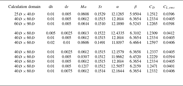
In order to verify the correctness of the calculations, a series of tests has been carried out regarding the configuration of a freely falling circular cylinder with a splitter plate. Independence studies of the domain size, the mesh spacing, the artificial Mach number, and the time step
 ${\textrm d}t$
, are performed, as shown in table 2. In the following simulations,
 ${\textrm d}h=0.01$
and
 ${\textrm d}t=0.005$
are used to ensure convergence of the calculation. The computational domain of the fluid field is set as
 $40D\times 60D$
, which is sufficiently large to render the impact of the boundary on the numerical results. The near-structure region
 $ [-2.6D,2.6D ]\times [-0.6,1.6D+L ]$
is discretised by the fine mesh spacing
 ${\textrm d}h=0.01$
, while the far field is discretised with stretched meshes to reduce computational effort. An independence study of the Lagrangian mesh spacing is also carried out, as shown in figure 3(a), which implies that the Lagrangian mesh spacing
 $\Delta l=0.02D$
is sufficient to ensure numerical accuracy while reducing computational effort. Finally, the effect of the initial angle of attack is examined, as shown in figure 3(b). It is evident that the variation of the initial angle of attack does not alter the kinematics of the freely falling circular cylinder with a splitter.
Validations of the present numerical method. (a) Time histories of the velocity of a freely falling circular cylinder, and their comparisons with the results of Namkoong et al. (Reference Namkoong, Yoo and Choi2008). In this case,
 $\rho ^\ast =1.01$
,
 $Ga=138$
,
 $L^\ast =0.0$
. Note that the fluctuation of
 $V_c$
is small and fluctuates around
 $V_c=2.5\ \rm{cm\ s}^{-1}$
, which is shown in the inset. (b) The mean rotation angle (
 $\theta$
) of a rotatable circular cylinder with a splitter plate of different lengths
 $L^\ast$
in the uniform flow and its comparison with the reference data (Cimbala & Garg Reference Cimbala and Garg1991; Assi et al. Reference Assi, Bearman and Kitney2009; Tang et al. Reference Tang, Zhu, Wang, Alam, Song and Chen2022). Here,
 ${Re}=160$
,
 $L^\ast =0.5{-}2.0$
. (c) The trajectory of a freely falling plate flutter in fluid at
 ${Re}=1147$
, comparing with the experiment of Andersen, Pesavento & Wang (Reference Andersen, Pesavento and Wang2005).

Comparison of translational (
 $U_x$
and
 $V_y$
) and angular (
 $\omega$
) velocities with experiment for the freely falling plate with different aspect ratios.

Numerical results for the Strouhal number
 $St$
, the turn angle
 $\alpha$
, the drift angle
 $\beta$
, the drag coefficient
 $C_D$
, and the root mean square of the lift coefficient
 $C_{L,rms}$
, obtained by set-ups with different domain sizes, mesh spacing
 ${\textrm d}h$
, time step
 ${\textrm d}t$
, and artificial Mach number
 $Ma$
, for the case with
 $\rho ^\ast =1.01$
,
 $Ga=100$
,
 $L^\ast =1.0$
.

Independence study for the case with
 $\rho ^\ast =1.01$
,
 $Ga=150$
,
 $L^\ast =1.0$
. (a) Independence study of the Lagrangian mesh spacing
 ${\Delta}l$
, with fixed Eulerian mesh spacing
 ${\Delta}h=0.01D$
. (b) Independence study of the initial angle of attack
 $\alpha _0$
.

3. Results and discussions
The validated numerical method is applied in this section for the study of the freely falling circular cylinder with a splitter plate in the infinite static fluid. Consistent with previous studies (Namkoong et al. Reference Namkoong, Yoo and Choi2008), the freely falling bare circular cylinder (
 $L^*=0.0$
) quickly reaches a stable state after an initial acceleration phase, settling into a primarily vertical trajectory with small amplitude of transverse oscillations. In contrast, attaching a splitter plate fundamentally alters this behaviour, often leading to the significant oblique trajectories that will be detailed in the following subsections. Comprehensiveness of the study is established by considering quite a wide range of dimensionless parameters, including the length of the splitter plate (
 $0.5 \leqslant L^\ast \leqslant 2.0$
), the Galileo number (
 $25 \leqslant Ga \leqslant 800$
), and the density ratio of the circular cylinder to the fluid (
 $1.01 \leqslant \rho ^\ast \leqslant 2.60$
).
(a–f) Time histories of the velocities
 $U_C\ \rm{(cm\ s}^{-1})$
,
 $V_C\ \rm{(cm\ s}^{-1})$
and
 $\omega _C\ \rm{(deg\ s}^{-1})$
for typical cases: (a) SF (
 $Ga=25$
,
 $\rho ^\ast =1.01$
,
 $L^\ast =1.0$
), (b) SOF (
 $Ga=50$
,
 $\rho ^\ast =1.01$
,
 $L^\ast =1.5$
), (c) SVOF (
 $Ga=150$
,
 $\rho ^\ast =1.01$
,
 $L^\ast =1.0$
), (d) ZOF (
 $Ga=400$
,
 $\rho ^\ast =1.01$
,
 $L^\ast =1.0$
), (e) LF (
 $Ga=800$
,
 $\rho ^\ast =1.01$
,
 $L^\ast =1.0$
) and ( f) CF (
 $Ga=800$
,
 $\rho ^\ast =1.20$
,
 $L^\ast =1.0$
). (g) A general overview of the trajectory of a freely falling circular cylinder with a splitter plate at typical modes of kinematics.

3.1. Kinematic states
In this subsection, a summary and categorisation of the phenomena identified in the calculations will be presented. In the range of dimensionless paramenters mentioned above, the freely falling circular cylinder with a splitter plate exhibits six typical kinematic modes, namely the steady falling (SF), the steady oblique falling (SOF), the small vibration oblique falling (SVOF), the zigzag oblique falling (ZOF), the locked falling (LF) and the chaotic falling (CF).
Figure 4 illustrates typical cases exhibiting the kinematic modes mentioned above. The distinct features of these modes are described as follows.
-
(i) Steady falling (SF): the circular cylinder reaches a steady state of vertical falling.
-
(ii) Steady oblique falling (SOF): the circular cylinder reaches a steady state of falling with unanimous non-vertical velocity. The symmetry breaking feature emerges.
-
(iii) Small vibration oblique falling (SVOF): the circular cylinder exhibits an oblique falling trajectory, accompanied by a periodic transverse motion with small amplitude.
-
(iv) Zigzag oblique falling (ZOF): the circular cylinder shows an oblique falling trajectory and a transverse oscillation with considerable amplitude. The motion becomes increasingly disordered as
 $Ga$
grows. This zigzag-shape motion with large amplitude of transverse motion was also found in studies of freely falling/rising spheres (Jenny et al. Reference Jenny, Duek and Bouchet2004; Horowitz & Williamson Reference Horowitz and Williamson2010).
-
(v) Locked falling (LF): the freely falling circular cylinder first follows the ZOF kinematic mode, then goes back to the vertical falling mode with better periodicity, such as the grey background region illustrated in figure 4(e). A similar phenomenon was also identified in experiments of freely falling/rising spheres (Jenny et al. Reference Jenny, Duek and Bouchet2004) and freely falling shperes with a rigid filament (Choi et al. Reference Choi, Lee, Roh and Kim2025).
-
(vi) Chaotic falling (CF): the motion of the circular cylinder exhibits a more chaotic behaviour. The direction of the oblique falling trajectory may be altered after an intermittent motion of the LF modes (see the grey background regions in figure 4 f). A similar phenomenon was also recognised by Jenny et al. (Reference Jenny, Duek and Bouchet2004).

In the following subsubsections, thorough discussions of each kinematic mode will be presented, together with a summary of the wake patterns.
3.1.1. The SF and SOF modes
As summarised at the start of § 3.1, the falling trajectory of the circular cylinder with a splitter plate is typically a straight vertical or oblique line (see figure 4
g), corresponding to the SF or SOF mode, respectively. Time histories of the velocities (
 $U_C$
,
 $V_C$
and
 $\omega _C$
) of the circular cylinder shown in figures 4(a) and 4(b) indicate the evolution towards a steady rate of falling. In contrast to the SF mode, a non-zero horizontal velocity
 $U_C=-0.3083\ \rm{cm\ s}^{-1}$
is presented in the present example exhibiting the SOF mode of kinematics.
Figure 5 presents the vorticity contours and the pressure distributions on the structure for the two typical cases, where
 ${\varTheta }$
is the angular coordinate of the circular cylinder, and
 $y$
is the coordinate on the plate; here,
 ${\varTheta }=\pm 180^{\circ }$
or
 $y=0$
represents the junction point between the splitter plate and the circular cylinder. It can be seen that for the SF mode, the steady wake is formed in the downstream of the circular cylinder. Shear layers with opposite vorticities are formed on the two sides of the circular cylinder, then vanish due to the dissipation. However, for the SOF mode, the circular cylinder with a splitter plate exhibited the symmetry breaking phenomenon during falling, manifesting as the rotation to turn angle
 $\alpha =5.5869^{\circ }$
and the inclined falling trajectory at drift angle
 $\beta =5.2826^{\circ }$
. The motion of the SOF mode represents a state that exceeds the Reynolds number of critical equilibria (Xu et al. Reference Xu, Sen and Gad-el Hak1990), but remains under the threshold Reynolds number of vortex shedding. Essentially, it is the flow instability that attracts the splitter plate to one side and thus breaks symmetricity about the vertical coordinate. Figure 5(b) shows the asymmetric pressure distribution on the structure, while the angular position of the stagnation point on the circular cylinder approximately locates at
 ${\varTheta }=18^{\circ }$
.
Vorticity contours (c,d) and the corresponding pressure distributions on the structure (a,b) for typical cases: (a,c) SF,
 $Ga=25$
,
 $\rho ^\ast =1.01$
,
 $L^\ast =0.5$
; (b,d) SOF,
 $Ga=50$
,
 $\rho ^\ast =1.01$
,
 $L^\ast =1.5$
. The red dashed lines and the solid lines in (a,b) represent the pressure distributions on the circular cylinder (C) and on the plate (P), respectively. The black dash-dotted line marks the position where
 ${\varTheta }=0^{\circ }$
.

Kinematic characteristics of the freely falling circular cylinder with a splitter plate showing the SVOF mode (
 $Ga=150$
,
 $\rho ^\ast =1.01$
,
 $L^\ast =1.0$
). (a) Time histories of
 $\alpha$
and
 $C_T$
. Four instants in a motion period are labelled by the lines i–iv. (b) The Lissajous figure
 $C_T$
–
 $C_T^{\prime}$
. (c) The PSD of
 $C_L$
,
 $C_D$
and
 $C_T$
.

3.1.2. The SVOF mode
With increased values of
 $Ga$
, vortex shedding occurs, which leads to small vibrations in the velocities of the circular cylinder with a splitter plate (see figure 4
c). Figure 6 illustrates the kinematic characteristics of the SVOF mode with the case of
 $Ga=150$
,
 $\rho ^\ast =1.01$
and
 $L^\ast =1.0$
. It is evident that the turn angle
 $\alpha$
shows periodic fluctuations with amplitudes within
 $2^{\circ }$
. Furthermore,
 $C_T$
exhibits two extremely large peaks of different sizes in one motion cycle. This is reflected in the presence of two closed cycles of different sizes on the Lissajous figure. And it leads to the appearance of the second frequency
 $f_2=0.3472$
on the power spectral density (PSD) figure (the first frequency
 $f_1=0.1736$
represents the frequency of motion).
Vorticity contours (b) and the corresponding pressure distributions on the structure (a) for the typical case exhibiting the SVOF mode of kinematics (
 $Ga=150$
,
 $\rho ^\ast =1.01$
,
 $L^\ast =1.0$
). Images i–iv illustrate the four instants in figure 6(a).

The second frequency is attributed to the vortex shedding at distinct positions of the circular cylinder with a splitter plate. As shown in figure 7(bi–biv), flow separation is observed on one side of the circular cylinder, from which a vortex is formed. The flow on the other side first detaches from the circular cylinder, then reattaches to the splitter plate; it is coiled along the plate, and finally forms a vortex behind the splitter plate. The reattachment phenomenon has been documented in the experiments conducted by Gu et al. (Reference Gu, Wang, Qiao and Huang2012). This type of wake that sheds two vortices within a single motion cycle is known as the 2S wake pattern. The pressure distribution corresponding to the vorticity contour is displayed in figure 7(ai–aiv). It can been seen that the stagnation point is at approximately
 ${\varTheta }=-19^{\circ }$
. The low pressure regions are found from the side of the circular to its rear, where the pressure is significantly lower on the side to which the circular cylinder is turned, which accounts for the drift motion of the circular cylinder.
Kinematic characteristics of the freely falling circular cylinder with a splitter plate showing the ZOF mode of kinematics, for (a–c)
 $Ga=300$
,
 $\rho ^\ast =1.20$
,
 $L^\ast =1.0$
and (d–f)
 $Ga=400$
,
 $\rho ^\ast =1.01$
,
 $L^\ast =1.0$
. (a,d) Time histories of
 $\alpha$
and
 $C_T$
. (b,e) The Lissajous figure
 $C_L$
–
 $C_L'$
. (c,f) The PSD of
 $C_L$
,
 $C_D$
and
 $C_T$
.

3.1.3. The ZOF mode
As outlined at the start of § 3.1, the amplitude of the transverse oscillation of the cases belonging to the ZOF kinematic mode is significantly larger than that of those categorised into the SVOF kinematic mode. To shed light on the transition mechanism, we plot the kinematic characteristics of the typical case (
 $Ga=300$
,
 $\rho ^\ast =1.20$
,
 $L^\ast =1.0$
) which just enters the ZOF mode in figure 8(a–c). It is shown that the fluctuation of the turn angle
 $\alpha$
increases considerably, and
 $C_T$
fluctuates four times in one motion cycle. The corresponding Lissajous figure
 $C_T$
–
 $C_T^{\prime}$
contains four cycles. And the PSD of
 $C_T$
presents a frequency
 $f_3=0.3572$
that is four times the frequency of motion
 $f_1=0.0893$
.
Further increasing the value of
 $Ga$
, clear disordered motions of the circular cylinder appear. Figure 8(d–f) illustrate the case at
 $Ga=400$
, which exhibits the worst periodicity for
 $\alpha$
and
 $C_T$
in the ZOF regime. Such disorder is confirmed in the Lissajous plot. Figure 8( f) exhibits a dominant frequency
 $f_1=0.0859$
and some insignificant sub-frequencies, indicating that the disorder exists within each cycle of the motion.
Vorticity contours (b) and the corresponding pressure distributions on the structure (a) for the typical case exhibiting the ZOF mode of kinematics (
 $Ga=300$
,
 $\rho ^\ast =1.20$
,
 $L^\ast =1.0$
). Images i–iv illustrate the four instants in figure 8(a).

Vorticity contours (b) and the corresponding pressure distributions on the structure (a) for the typical case exhibiting the ZOF mode of kinematics (
 $Ga=400$
,
 $\rho ^\ast =1.01$
,
 $L^\ast =1.0$
). Images i–viii illustrate the eight instants in figure 8(d).

Snapshots of the vorticity contours and the pressure distributions of the two typical cases are presented in figures 9 and 10, which illustrate the development of the disorder in the flow field. The case with relatively lower
 $Ga$
exhibits the 2P wake pattern where two pairs of vortices are shed successively in one cycle of motion (see figure 9). The other case, with relatively larger
 $Ga$
, presents certain disorders in the two cycles illustrated in figure 10: two vortex pairs and one single vortex are shed in the first cycle of motion (see figure 10(bi–biv)), which forms the 2P + 1S wake pattern; and two vortex pairs and two single vortices are shed in the next cycle of motion (see figure 10(bv–bviii)), which belongs to the 2P + 2S wake pattern. The variations in the wake pattern exert a direct influence on the pressure distribution on the structural surface (see figure 10(ai–aviii)), and finally lead to subtle differences in each motion cycle. For the cases belonging the ZOF mode, this kind of disorder develops progressively as
 $Ga$
increases, leading to uncertain wake patterns in each cycle of motion, which is termed the 2P + nS wake pattern in this paper.
3.1.4. The LF mode
As discussed at the start of § 3.1, for cases exhibiting the LF mode of kinematics, the falling trajectory of the circular cylinder with a splitter plate could finally return to the vertical path with minor transverse oscillations. Taking the case with
 $Ga=800$
,
 $\rho ^\ast =1.01$
and
 $L^\ast =1.0$
as an example, the circular cylinder presents the oblique falling tendency in the initial stage, then abruptly switches to the vertical falling trajectory (see the purple line in figure 4
g). In figure 4(e), it can be seen that before
 $TU_{\textit{ref}}/D=49$
, the curves of the velocity components
 $U_C$
and
 $V_C$
and the angular velocity
 $\omega _C$
of the circular cylinder present large amplitudes of oscillation with approximately the same frequency, which is analogous to the observations in the ZOF mode. After
 $TU_{\textit{ref}}/D=49$
, the oscillation amplitude of the vertical velocity component
 $V_C$
is largely reduced, with its frequency doubled. Correspondingly, the falling trajectory of the circular cylinder is shifted to a vertical path with minor transverse oscillations. Similar mode-switching phenomena were identified in experiments of freely falling/rising spheres (Jenny et al. Reference Jenny, Duek and Bouchet2004). Recently, Choi et al. (Reference Choi, Lee, Roh and Kim2025) also experimentally reported a similar large-amplitude, periodic vertical motion for a freely falling sphere with a rigid rear filament at Reynolds numbers of
 $O(10^3)$
.
Kinematic characteristics of the freely falling circular cylinder with a splitter plate showing the LF mode of kinematics (
 $Ga=800$
,
 $\rho ^\ast =1.01$
,
 $L^\ast =1.0$
). (a) Time histories of
 $\alpha$
and
 $C_T$
. Four instants in a motion period are labelled by the lines i–iv. (b) The Lissajous figure
 $C_T$
–
 $C_T^{\prime}$
. (c) The PSD of
 $C_L$
,
 $C_D$
and
 $C_T$
.

Vorticity contours (b) and the corresponding pressure distributions on the structure (a) for the typical case exhibiting the LF mode of kinematics (
 $Ga=800$
,
 $\rho ^\ast =1.01$
,
 $L^\ast =1.0$
). Images i–iv illustrate the four instants in figure 11(a).

Figure 11 illustrates the kinematic characteristics in the vertical falling state of the typical LF mode with
 $Ga=800$
,
 $\rho ^\ast =1.01$
and
 $L^\ast =1.0$
. Comparing with the earlier case with
 $Ga=400$
, showing the ZOF kinematic mode (see figure 8(d–f)), the larger
 $Ga$
in this case surprisingly helps to restore the periodicity of
 $\alpha$
and
 $C_T$
. Referring to the Lissajous figure of
 $C_T$
–
 $C_T^{\prime}$
, a concentrated centre-symmetric and polycyclic shape shows up, which suggests good periodicity and symmetry of the falling motion. Furthermore, the frequency of
 $C_D$
is twice the frequency of motion
 $f_1=0.1231$
(see figure 11
c), which is significantly different from the results for the other kinematic modes. This indicates that
 $C_D$
undergoes two rounds of acceleration/deceleration in a circle of motion of the circular cylinder, whereas
 $C_L$
and
 $C_T$
undergo one circle. This phenomenon can be attributed to the unique wake pattern of the LF kinematic mode. As
 $Ga$
increases, the fluid viscosity is weakened, which facilitates the vortex shedding. The wake of the cases belonging to the LF mode of kinematics generally follows the 2P + 2S pattern, which is also more regularised compared to the wake patterns associated with the ZOF kinematic mode. As highlighted in the red dashed circles in figure 12(bi–biv), the first 1P + 1S vortices are shed when the circular cylinder travels from left to right, and the subsequent 1P + 1S vortices are shed when it moves from right to left. The detachment of every set of 1P + 1S vortices would trigger fluctuations in the pressure distributions on the circular cylinder (from figure 12(aii) to figure 12(aiii), and from figure 12(aiv) to figure 12(ai)), which results in
 $C_D$
being influenced twice in one cycle of motion.
3.1.5. The CF mode
At even higher
 $Ga$
, the motion behaviour of the free fall of the circular cylinder with a splitter plate returns to a disordered manner. In this case, the kinematics may consist of multiple modes that are difficult to distinguish. For example, the grey background region in figure 4( f) presents short-term kinematics that is analogous to the LF mode, while the falling direction may be switched between these intermittent periods of motion. In this paper, the term ‘chaotic falling’ (CF) is employed to describe this particular type of falling motion.
The kinematic characteristics displayed in figure 13 reveal the pronounced chaotic behaviour of the CF mode. The time histories of
 $\alpha$
and
 $C_T$
exhibit poor periodicity (see figure 13
a), and the Lissajous map evolves to fractal distributions (see figure 13
b), which is more intricate than the ZOF mode illustrated in figure 8(e), and thus indicates stronger disorders. Furthermore, the PSD diagrams of
 $C_L$
,
 $C_D$
and
 $C_T$
present a complex broadband spectrum, and the dominance of the main frequency
 $f_1$
is no longer significant.
Kinematic characteristics of the freely falling circular cylinder with a splitter plate showing the CF mode of kinematics (
 $Ga=800$
,
 $\rho ^\ast =1.20$
,
 $L^\ast =1.0$
). (a) Time histories of
 $\alpha$
and
 $C_T$
. Four instants in a motion period are labelled by the lines i–iv. (b) The Lissajous figure
 $C_T$
–
 $C_T^{\prime}$
. (c) The PSD of
 $C_L$
,
 $C_D$
and
 $C_T$
.

Vorticity contours (b) and the corresponding pressure distributions on the structure (a) for the typical case exhibiting the LF mode of kinematics (
 $Ga=800$
,
 $\rho ^\ast =1.20$
,
 $L^\ast =1.0$
). Images i–iv illustrate the four instants in figure 13(a).

In order to illustrate the chaotic features of the wake pattern, four instantaneous vorticity contours in one motion cycle are shown in figure 14. Categorisation of the complex vortex structures observed in this figure to a specific wake pattern is difficult. Therefore, the term ‘chaotic wake pattern’ is used in this paper.
3.2. Parametric associations of the kinematic mode and the wake pattern
Although quantitative recognitions have been gained in Choi, Jeon & Kim (Reference Choi, Jeon and Kim2008) that the attachment of a splitter plate behind a bluff body could suppress the vortex shedding and reduce drag and lift fluctuations, the parametric range for which the splitter plate can stabilise the freely falling motion of a circular cylinder remains unclear. To address this issue, this subsection investigates a range of cases with various plate lengths (
 $0.5 \leqslant L^\ast \leqslant 2.0$
), density ratios (
 $1.01 \leqslant \rho ^\ast \leqslant 2.60$
) and Galileo numbers (
 $25 \leqslant Ga \leqslant 800$
). The range of the density ratio considered here covers the real conditions of common fishes and corals.
Overview of the typical kinematic modes and regimes of wake patterns on the
 $Ga{-}\rho ^\ast$
diagram for the freely falling circular cylinder with a splitter plate with different lengths: (a)
 $L^\ast =0.5$
, (b)
 $L^\ast =1.0$
, (c)
 $L^\ast =1.5$
and (d)
 $L^\ast =2.0$
. The phase diagrams are subdivided approximately into sub-regimes based on the wake patterns.

Numerical results of the Strouhal number
 $St$
, the turn angle
 $\alpha$
, the drift angle
 $\beta$
, and the amplitude of the turn angle
 $\alpha _{amp}$
obtained by set-ups with different plate mass.

The kinematic modes and the wake patterns of four data sets classified by the length of the splitter plate are illustrated in the phase diagram in figure 15. Each symbol represents a simulation case, and the background colour represents the approximate distribution regime of the wake patterns.
It is evident that cases exhibiting the SF or SOF modes of kinematics are observed in the low-
 $Ga$
region. As
 $Ga$
increases, the SVOF, ZOF, LF and CF modes of kinematics emerge in sequence for the freely falling circular cylinder with a splitter plate (see figure 15). To assess the mass of the splitter plate, simulations with finite plate masses (
 $m_p=0.01\rho _sL, 0.001\rho _sL$
, where
 $\rho _s=1.10\ \rm{g\ cm}^{-3}$
and
 $L=1.0\ {\textrm{cm}}$
) and thus modified centre of mass and moment of inertia are carried out. Figure 16 demonstrates that the kinematic modes generally remain consistent, although minor shifts of the results can be observed in the ZOF modes. This confirms that the finite mass of the splitter plate has limited influence on the freely falling motion.
Moreover, an inter-correlation between the wake pattern and the kinematic mode could be identified. The steady wake patterns are only observed at low
 $Ga$
, which are insufficient for vortex shedding and thus correspond to the SF or SOF mode of kinematics. At higher
 $Ga$
, the 2S wake pattern is usually associated with the SVOF mode of kinematics, while the ZOF mode of kinematics is usually correlated with the 2P + nS wake pattern. A thorough examination of the available data reveals that the 2P + 2S wake pattern is observed in the wake of cases exhibiting the LF mode of kinematics. In such circumstances, the motion and the wake pattern of the circular cylinder are interconnected, resulting in enhanced periodicity. However, as
 $Ga$
is increased further, the lock-in between the cylinder motion and the wake pattern is disrupted, and the chaotic features emerge in both the cylinder motion and its ambient flow pattern. Consequently, the wakes of the cases belonging to CF mode of kinematics are classified into the chaotic wake pattern. In addition, evidence suggests that the LF modes are more likely to occur at lower
 $\rho ^\ast$
. This phenomenon can be explained by the principle that structures with low
 $\rho ^\ast$
have smaller inertia and thus are more susceptible to the hydrodynamic forces, which can result in the LF modes. In contrast, structures with high
 $\rho ^\ast$
possess larger inertia, leading to a delay in the transition of the kinematic mode and the wake pattern with the growth of
 $Ga$
.
3.3. The oscillation amplitude of the turn angle
A noteworthy discovery from § 3.1 is the significant variation in the oscillation amplitude of the turn angle of the circular in different cases. Figure 17 shows the phase diagram of the oscillation amplitude of the turn angle
 $\alpha _{amp}$
. It is evident that
 $\alpha _{amp}$
increases gradually with
 $Ga$
, and is related to the kinematic modes. The magnitude of
 $\alpha _{amp}$
for each kinematic mode is found to be LF
 $\gt$
CF
 $\gt$
ZOF
 $\gt$
SVOF
 $\gt$
SOF
 $=$
SF
 $=$
0, where a steep gradient exists at the boundary between the SVOF mode and the ZOF/LF modes. This transition can be considered as a shift between the gravity-dominated modes (SF/SOF/SVOF) and the hydrodynamic-dominated modes (ZOF/LF/CF). The former represents that the falling motion of the structure is dominated by steady gravity, which is characterised by small oscillation amplitude of its self-rotation that presents minor variation with increasing
 $Ga$
at the same
 $\rho ^\ast$
. The latter represents motions dominated by the hydrodynamic forces, as evidenced by the surging oscillation amplitudes of self-rotation with increasing
 $Ga$
at the same
 $\rho ^\ast$
. Furthermore, it is notable that the gravity-dominated modes with higher
 $\rho ^\ast$
could emerge at higher
 $Ga$
, which is analogous to the study of Seyed-Ahmadi & Wachs (Reference Seyed-Ahmadi and Wachs2019) on the velocity fluctuations of spheres.
Diagrams of the oscillation amplitude of the turn angle
 $\alpha _{amp}$
on the phase space of
 $Ga$
and
 $\rho ^\ast$
. The images present the phase diagrams at different lengths
 $L^\ast$
of the splitter plate: (a)
 $L^\ast =0.5$
, (b)
 $L^\ast =1.0$
, (c)
 $L^\ast =1.5$
and (d)
 $L^\ast =2.0$
. The symbols are filled with distinct colours as assigned in figure 15 for the specific wake pattern.

3.4. The falling velocity
As stated in § 3.1, the attachment of the splitter plate to the rear of the circular cylinder can tilt its falling trajectory. In such cases, the falling velocity would have the horizontal and vertical components. In this subsection, the phase diagrams of the two velocity components are presented to investigate their contributions in the falling motion. Specifically, to illustrate the significance of the horizontal velocity component
 $U$
in the total falling velocity
 $U_{\textit{ref}}$
, the normalised horizontal velocity
 $U/U_{\textit{ref}}$
is used in figure 18. Meanwhile, to shed light on the effect of the splitter plate, the vertical velocity component
 $V$
is normalised by the falling velocity of the freely falling bare circular cylinder with the same parametric settings (
 $U_{ref(L^\ast = 0.0)}$
), as shown in figure 19.
Diagrams of the normalised horizontal velocity
 $U/U_{\textit{ref}}$
on the phase space of
 $Ga$
and
 $\rho ^\ast$
. The images present the phase diagrams at different lengths
 $L^\ast$
of the splitter plate: (a)
 $L^\ast =0.5$
, (b)
 $L^\ast =1.0$
, (c)
 $L^\ast =1.5$
and (d)
 $L^\ast =2.0$
. The symbols are filled with distinct colours assigned as in figure 15 for the specific wake pattern.

Diagrams of the normalised vertical velocity
 $V/U_{ref(L^\ast =0.0)}$
on the phase space of
 $Ga$
and
 $\rho ^\ast$
, where
 $U_{ref(L^\ast =0.0)}$
is the reference velocity of the freely falling bare circular cylinder with the same
 $Ga$
and
 $\rho ^\ast$
. The images present the phase diagrams at different lengths
 $L^\ast$
of the splitter plate: (a)
 $L^\ast =0.5$
, (b)
 $L^\ast =1.0$
, (c)
 $L^\ast =1.5$
and (d)
 $L^\ast =2.0$
. The symbols are filled with distinct colours as assigned in figure 15 for the specific wake pattern.

As shown in figure 18, it is evident that as
 $Ga$
increases, the contributions from the horizontal component of the falling velocity grow until the onset of the ZOF mode. Thereafter, the normalised horizontal velocity decreases, and finally approaches zero after entering the regimes of the LF or CF modes. Furthermore, it is found that specific
 $L^\ast$
and
 $\rho ^\ast$
enable the circular cylinder to possess larger horizontal velocities. For example, the case
 $L^\ast =1.5$
,
 $\rho ^\ast =1.8$
at
 $Ga=600$
has the largest normalised horizontal velocity among all cases.
It is interesting that in most cases, attaching the splitter plate to the rear of the circular cylinder would accelerate its falling. In the cases with low
 $Ga$
or large
 $\rho ^\ast$
that exhibit oblique falling mode, the vertical velocity component is larger than that of the bare circular cylinder (note that the horizontal velocity component of the bare circular cylinder in these cases is negligible, therefore
 $U_{ref(L^\ast =0.0)}$
can represent its vertical velocity component). Furthermore, the acceleration induced by the presence of the splitter plate is more pronounced at higher
 $Ga$
. However, for cases belonging to the LF mode of kinematics, a deceleration effect could emerge in the presence of the splitter plate. This is consistent with recent experiments (Choi et al. Reference Choi, Lee, Roh and Kim2025) on a freely falling sphere with a filament, which exhibit a large-amplitude zigzag motion with a deceleration in the vertical velocity. This deceleration can be attributed to the distinct locations of vortex shedding. For the cases belonging to the LF mode, the vortex shedding occurs closely behind the circular cylinder (see figure 12
b), which results in the low pressure region in its downstream vicinity and thus provides resistance to the falling. And the vertical velocity component
 $V$
undergoes two rounds of acceleration/deceleration within one cycle of motion, as discussed in § 3.1.4. For the cases of the SVOF and ZOF modes, vortex shedding occurs on the downstream slanting side of the structure, due to which the low pressure region is relatively more distant from the cylinder surface, and the suction effect is reduced. In these cases, the vertical velocity component
 $V$
normally experiences one acceleration/deceleration process within one cycle of motion.
Moreover, it is found that in the gravity-dominated modes (SF/SOF/SVOF), the phase diagrams of the horizontal and vertical velocity components show a predominantly vertical distribution, while in hydrodynamic-dominated modes (ZOF/LF/CF), the phase diagrams of the two velocity components both show a predominantly horizontal distribution. This observation indicates that in the gravity-dominated modes, the horizontal and vertical velocity components are less influenced by the density ratio
 $\rho ^\ast$
, suggesting a strong correlation between
 $Ga$
and the falling velocity in these instances. Conversely, in hydrodynamic-dominated modes, velocity fluctuations resulting from vortex shedding substantially modulate the kinematics, resulting in the decoupling between
 $Ga$
and the falling velocity.
(a) The Reynolds number
 ${Re}$
for different kinematic modes as a function of the Galileo number
 $Ga$
. (b) The Reynolds number
 ${Re}$
for different splitter plate lengths as a function of the Galileo number
 $Ga$
.

Figure 20 reveals the relationship between the Reynolds number and the Galileo number in different kinematic modes and for different lengths of the splitter plate. For the gravity-dominated modes, the reference velocity is determined by the balance between the gravity and the relatively steady drag force. And
 ${Re}$
demonstrates a quasi-linear correlation with
 $Ga$
. In contrast, the hydrodynamic-dominated modes show significant deviations from this trend, which are characterised by large, unsteady oscillations driven by the complex vortex shedding behaviours. In this regime, the splitter plate becomes a crucial participant when it contributes to the unsteady dynamics, which substantially modulates the falling velocity.
3.5. Lyapunov exponent analysis for kinematics
While § 3.1 illustrated the chaotic features of the system via PSD and phase-space Lissajous figures, a more quantitative measure can be obtained through the computation of the maximum Lyapunov exponent
 $\lambda _{max}$
(see A.3 for the explanation of
 $\lambda _{max}$
). As shown in figure 21, the data are categorised into four distinct kinematic modes, each represented by different symbols. It is evident that the chaotic behaviours in the system grow with
 ${Re}$
. The maximum Lyapunov exponents are all negligible at low Reynolds numbers, indicating that the motions of the SVOF modes in this range exhibit periodic behaviours. At higher Reynolds numbers, other kinematic modes show up, which is accompanied by a significant increase in
 $\lambda _{max}$
, implying the growth of flow complexity and the emergence of non-periodic behaviours. In particular, the LF modes have smaller values of
 $\lambda _{max}$
, while the CF modes have higher values of
 $\lambda _{max}$
, exceeding 0.2 at many points. This divergence in trends reveals different mechanisms: the LF modes have more ordered motions at higher values of
 ${Re}$
, while the CF modes develop more chaotic motions.
The variation of the maximum Lyapunov exponents
 $\lambda _{max}$
with
 ${Re}$
for the rotational component of the freely falling motion of the circular cylinder with a splitter plate.

3.6. Estimation of the Strouhal number
In this subsection, further investigation of the vortex shedding frequency, which is characterised by the Strouhal number, is carried out. For the present study of a freely falling circular cylinder with a splitter plate, given the complexity and disorder of vortex shedding at larger
 ${Re}$
, the analysis of the Strouhal number conducted here is limited to the Reynolds number that makes the maximum Lyapunov exponent negligible.
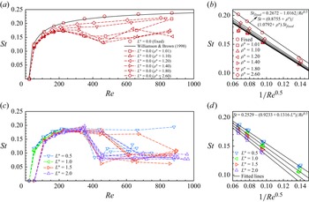
(a) The relationship between
 ${Re}$
and
 $St$
for a freely falling bare circular cylinder and a fixed circular cylinder, compared with the results in Williamson & Brown (Reference Williamson and Brown1998). The dashed lines include case series with six different density ratios, i.e.
 $\rho ^\ast =1.01$
,
 $1.10$
,
 $1.20$
,
 $1.40$
,
 $1.80$
and
 $2.60$
. (b) The
 ${\textit{Re}}^{-0.5}{-}St$
relation for a freely falling bare circular cylinder. The symbols are the results of the present study, and the solid lines are the fitted results given by Namkoong et al. (Reference Namkoong, Yoo and Choi2008). (c) The relationship between
 ${Re}$
and
 $St$
for a freely falling circular cylinder with different lengths of splitter plate and six different density ratios. (d) The
 ${\textit{Re}}^{-0.5}{-}St$
relation for a freely falling circular cylinder with different lengths of splitter plate and six different density ratios.

The analysis starts from the established relationship between the vortex shedding frequency
 $St$
and the Reynolds number
 ${Re}$
for the vortex shedding frequency of flow past a fixed circular cylinder (Williamson & Brown Reference Williamson and Brown1998), which reads
 \begin{equation} St_{\textit{fixed}}=k_A+\frac {k_B}{\sqrt {\textit{Re}}}, \end{equation}
where
 $k_A$
and
 $k_B$
are two constants. Here,
 $k_A$
is related to the geometry of the structure, and
 $k_B/\sqrt {\textit{Re}}$
is related to the thickness of the shear layer (Williamson & Brown Reference Williamson and Brown1998). Figure 22(a) shows the good agreement between the present results and the reference data of Williamson & Brown (Reference Williamson and Brown1998) (
 $k_A=0.2665$
and
 $k_B=-1.0180$
). Also included in this figure are the results of six different density ratios. A general tendency is that
 $St$
would grow as
 ${Re}$
increases. At the same
 ${Re}$
, the variation of the density ratio affects the value of
 $St$
. The relation between
 $St$
and
 ${Re}$
for the freely falling circular cylinder with different density ratios can be established based on the linear correlation between
 $St$
and
 $\rho ^\ast$
as proposed by Namkoong et al. (Reference Namkoong, Yoo and Choi2008):
 \begin{equation} St=\left (\frac {\rho ^\ast +k_C}{\rho ^\ast +k_D}\right )St_{\textit{fixed}}=\left (\frac {\rho ^\ast +k_C}{\rho ^\ast +k_D}\right )\left(k_A-\frac {k_B}{\sqrt {\textit{Re}}}\right), \end{equation}
where
 $k_C$
and
 $k_D$
are constants, and
 $St_{\textit{fixed}}$
is obtained from (3.1). Namkoong et al. (Reference Namkoong, Yoo and Choi2008) reported the constants as
 $k_A=0.2672$
,
 $k_B=-1.0162$
,
 $k_C=0.8755$
and
 $k_D=1.0792$
. Figure 22(b) shows the comparison between the present results and those of Namkoong et al. (Reference Namkoong, Yoo and Choi2008). Note that the leftmost set of data (
 ${Re}\cong 210$
) deviates slightly from the fitted results due to the surging instability of the wake. For
 ${Re} \leqslant 190$
, the prediction equation (3.2) presents appealing accuracy.
For a freely falling bare circular cylinder, the shedding frequency is strongly correlated with the inertia of the circular cylinder (
 $\rho ^\ast$
), as its oscillatory response dictates the vortex shedding process. However, the attachment of a splitter plate fundamentally alters this dynamic. The effect of the density ratio and the plate length on
 $St$
is illustrated in figure 22(c), which demonstrates correlations between these parameters. The attachment of the splitter plate stabilises the near wake and delays vortex formation, causing the shedding dynamics to be governed primarily by the geometry of the combined body and the development of viscous shear layers along its surfaces. This geometric and viscous control of the wake is the dominant mechanism, which overshadows the influence of the inertia of the circular cylinder (
 $\rho ^\ast$
). However, it is observed that the length of the splitter plate could alter the vortex shedding frequency significantly. In the range
 ${Re}\leqslant 260$
, and considering cases with vortex shedding (i.e.
 $St\neq 0$
), the freely falling circular cylinder with a splitter plate exhibits the SVOF mode of kinematics, which corresponds to shedding two opposite vortices from the circular cylinder and the splitter plate within a single cycle of motion. Therefore, modification should be made to (3.1) to reflect the role of the plate length, which is tentatively proposed as
 \begin{equation} St=k_A+\frac {k_B+k_C\times L^\ast }{\sqrt {\textit{Re}}}, \end{equation}
where
 $k_A$
is a constant related to the geometry of the structure, and
 $k_B/\sqrt {\textit{Re}}$
and
 $k_C/\sqrt {\textit{Re}}$
are related to the thicknesses of the shear layers on the circular cylinder and on the plate, respectively. Fitted values of the constants are
 $k_A=0.2529$
,
 $k_B=-0.9223$
and
 $k_C=-0.1316$
. And the fitted results show good agreement with the simulation data, as presented in figure 22(d).
3.7. Estimation of angles
In the range of parameters considered in this paper, attaching a splitter plate to the rear of a freely falling circular cylinder could alter its kinematic characteristics. The circular cylinder may rotate to the turn angle
 $\alpha$
, and its falling trajectory is tilted to the drift angle
 $\beta$
(see figure 23). This subsection will discuss the estimation of these two important angles. It should be noted that the analysis in this subsection is based on the assumption of a quasi-steady state that can determine specific values of the angles, due to which unsteady cases, such as those belonging to the ZOF, LF or CF modes with significant oscillation amplitudes in their rotating angles, have been excluded from the present discussion. Figures 24(c) and 24(e) show the variation of angles
 $\alpha$
and
 $\beta$
with the Reynolds number. It can be observed that in the range
 ${Re}\gt 50$
(except the cases with
 $L^\ast =0.5$
), the turn angle
 $\alpha$
is decreasing with
 ${Re}$
, while the drift angle
 $\beta$
undergoes a gradual increase.
Time-averaged schematic with vorticity and structure contour.

The turn angle
 $\alpha$
and the drift angle
 $\beta$
should be related to the forces acting on the structure. When the circular cylinder with a splitter plate falls in the fluid, the hydrodynamic forces and the gravity are balanced over the course of time. Figure 23 shows the time-averaged vorticity contour, the gravity
 $G$
, the time-averaged hydrodynamic forces
 $f_x$
and
 $f_y$
on the plate, and
 $F_x$
and
 $F_y$
on the circular cylinder. The force balance relationship can be expressed as
 \begin{align}&\qquad\qquad\quad F_x+f_x = 0, \end{align}
 \begin{align}& F_y+f_y =G-\rho gV_B=(\rho _s-\rho )gV_B, \end{align}
 \begin{align}& f_xl_x\cos (\alpha ) +f_yl_y\sin (\alpha )+\frac {F_\tau D}{2} =0, \end{align}
where
 $l_x$
and
 $l_y$
are the average arms of
 $f_x$
and
 $f_y$
about the centre of the circular cylinder, respectively,
 $V_B$
is the volume of the structure, and
 $F_\tau$
is the tangential hydrodynamic force acting on the surface of the circular cylinder. It should be noted that
 $l_x$
and
 $l_y$
do not necessarily correspond to one another. Performing the first-order Taylor expansion for
 $\cos (\alpha )$
and
 $\sin (\alpha )$
, and substituting (3.5) into (3.6), the estimation formulation for the turn angle
 $\alpha$
can be derived as
 \begin{equation} \alpha =-\frac {f_xl_x}{f_yl_y}-\frac {F_\tau D}{2f_yl_y} \cong k_1\frac {f_x}{(\rho _s-\rho )gV_B}L^\ast +A, \end{equation}
where it is assumed that
 $L^\ast \cong l_x/l_y$
,
 $f_y=(\rho _s-\rho )gV_B-F_y\cong (\rho _s-\rho )gV_B/k_1$
,
 $k_1$
is a correction factor, and
 $A$
is a constant that represents the second term in (3.7) resulting from the operation.
The variation of (a) the time-averaged hydrodynamic force
 $f_x$
, (c) the turn angle
 $\alpha$
, and (e) the drift angle
 $\beta$
with
 ${Re}$
. (b) The force
 $f_x$
as a function of
 $\rho U_{\textit{ref}}^2L\,{\textit{Re}}^{0.5}$
. (d) The turn angle
 $\alpha$
as a function of
 ${L^\ast }^{2}\,{\textit{Re}}^{2.5}/{Ga}^{2}$
. ( f) The drift angle
 $\beta$
as a function of
 $L^\ast\, {\textit{Re}}^{2.5}/{Ga}^{2}$
.

The estimation formulation of the drift angle
 $\beta$
can be derived as
 \begin{equation} \beta =\tan^{-1}{\left (\frac {{\textrm d}x}{{\textrm d}y}\right )}=\tan^{-1}{\left (\frac {UT}{VT}\right )}\cong \tan^{-1}{\left (\frac {F_t}{F_d}\right )}\cong k_2\frac {f_x}{(\rho _s-\rho )gV_B}, \end{equation}
where
 ${\textrm d}x$
and
 ${\textrm d}y$
are the horizontal and vertical displacements of the structure in unit time, respectively,
 $U$
and
 $V_B$
are the horizontal and vertical velocities, respectively,
 $T$
is the unit time,
 $F_t$
and
 $F_d$
are the drift and drag forces, respectively, and
 $k_2$
is a correction factor. The components
 $F_x$
and
 $f_x$
ensure the force balance in the horizontal direction, while the components
 $F_y$
and
 $f_y$
counteract
 $(\rho _s-\rho )gV_B$
, thereby maintaining equilibrium in the vertical direction. Therefore, the variables
 $F_t$
and
 $F_d$
can be replaced with
 $f_x$
and
 $(\rho _s-\rho )gV_B$
, respectively.
Assuming that the force
 $f_x$
on the plate is a steady force, and considering the effect of viscosity,
 $f_x$
can be estimated by
 \begin{equation} f_x=k_3\rho U_{\textit{ref}}^2\,L\,\sqrt {\textit{Re}}, \end{equation}
where
 $k_3$
is a correction factor that accounts for the attack angle of the splitter plate and other geometric effects.
Figures 24(a) and 24(b) show the variation of
 $f_x$
with
 ${Re}$
and the fitted results based on the above estimation formulations, respectively. It can be observed that the fitting is quite satisfactory with
 $k_3=0.0028$
. It should be noted that
 $f_x$
is a dimensional quantity.
It is observed that (3.7) and (3.8) have the common term
 $f_x/(\rho _s-\rho )gV_B$
, which can be simplified by substituting (3.9):
 \begin{equation} \frac {f_x}{(\rho _s-\rho )gV_B}=\frac {4k_3}{\unicode{x03C0} }L^\ast \frac {{\textit{Re}}^{2.5}}{{Ga}^{2}}. \end{equation}
The remaining free parameters in the estimations (3.7) and (3.8) for the turn angle
 $\alpha$
and the drift angle
 $\beta$
can be readily obtained by fitting the present simulation results, which gives the final estimations as
 $\alpha \cong -0.2187{L^\ast }^{2}\,{\textit{Re}}^{2.5}/{Ga}^{2}+13.2333$
and
 $\beta \cong 0.3569L^\ast\, {\textit{Re}}^{2.5}/{Ga}^{2}$
. Figures 24(d) and 24( f) illustrate the fitted results for the present simulation and the validation of the above estimation formulations against the reference data in Lācis et al. (Reference Lācis, Brosse, Ingremeau, Mazzino, Lundell, Kellay and Bagheri2014) (
 $0.2 \leqslant L^\ast \leqslant 2.0$
). Quite good agreement with the simulation results is shown in these figures, which implies the rationale of the above analyses stemming from the force balance perspective. It should be noted that the effectiveness of the estimation formulas presented in this subsection are subject to certain limitations when being applied to a wider range of parameters. In particular, the estimation of
 $\alpha$
could deteriorate in the cases with shorter plate lengths, when the turn angle may exhibit large values, e.g. the case
 $L^\ast =0.5$
and the first few data points in Lācis et al. (Reference Lācis, Brosse, Ingremeau, Mazzino, Lundell, Kellay and Bagheri2014) in figure 24(d). The reason for such deterioration is that the first-order Taylor expansion employed in the derivation could bring a large truncation error in these circumstances. In addition, larger plate length can help to stabilise the structure and thus remove the symmetry breaking characteristic (e.g. the case with
 $L^\ast =2.0$
and
 ${Re}=45$
in Lācis et al. (Reference Lācis, Brosse, Ingremeau, Mazzino, Lundell, Kellay and Bagheri2014), where the prediction of the turn angle
 $\beta$
is no longer available). Furthermore, when the Reynolds number is high, the estimation of
 $\beta$
may expect larger deviation. As general guideline for applications of the estimation formulas, cases with Reynolds number
 ${Re}\lt 260$
and the length of the splitter plate
 $0.5\lt L^\ast \lt 2.0$
can expect good accuracy of prediction, while the estimation accuracy for cases beyond these ranges of parameters may depend on whether a quasi-steady kinematic mode can be revealed. Nevertheless, the estimations of the turn angle and the drift angle presented in this subsection shed light on the underlying mechanisms of the freely falling circular cylinder with a splitter plate, and could be of reference value to engineering applications such as inclined landing.
4. Concluding remarks
In this paper, numerical investigation of a freely falling circular cylinder attached to a splitter plate in an infinite fluid domain under gravity is carried out, using the lattice Boltzmann flux solver and the immersed boundary method. Variations of key dimensionless parameters, including the length of the splitter plate (
 $0.5 \leqslant L^\ast \leqslant 2.0$
), the Galileo number (
 $25 \leqslant Ga \leqslant 800$
) and the density ratio of the circular cylinder to the fluid (
 $1.01 \leqslant \rho ^\ast \leqslant 2.60$
), are considered. The following conclusions can be drawn from the results presented.
-
(i) The kinematics of the freely falling circular cylinder with a splitter plate can be categorised into the steady falling (SF), the steady oblique falling (SOF), the small vibration oblique falling (SVOF), the zigzag oblique falling (ZOF), the locked falling (LF) and the chaotic falling (CF) modes. The falling modes show dependency on dimensionless parameters such as the plate length, the Galileo number and the density ratio.
-
(ii) The wake patterns of the freely falling circular cylinder with a splitter plate are identified, and a correlation between the wake patterns and the kinematic modes is revealed. The wake pattern can be categorised into four types: the steady wake, the 2S, the 2P + nS, the 2P + 2S, and the chaotic wake, which correspond to the SF/SOF, SVOF, ZOF, LF and CF modes of kinematics, respectively.
-
(iii) The influence of
$\rho ^\ast$
on the vortex shedding frequency would be diminished by attaching a splitter plate to the freely falling circular cylinder. Namkoong et al. (Reference Namkoong, Yoo and Choi2008) found a linear relationship between vortex shedding frequency
$St$
and
$\rho ^\ast$
for the freely falling circular cylinder without a splitter plate. However, the attachment of a splitter plate to the rear of the circular cylinder could greatly alter the Strouhal number, and enlarge the effect posed by the fluid viscosity. A correlation formulation has been established based on the vortex shedding characteristics to quantify the effect of the plate length and the Reynolds number on the Strouhal number, which shows good agreement with the numerical results. -
(iv) Attachment of a splitter plate can rotate the freely falling cylinder to the turn angle
$\alpha$
and tilt its falling trajectory to the drift angle
$\beta$
. At a fixed value of
${Re}$
, larger
$L^\ast$
results in smaller
$\alpha$
and larger
$\beta$
. Force balance analyses have been carried out in quasi-steady conditions, which give estimation formulations for the turn angle
$\alpha$
and the drift angle
$\beta$
. The estimation formulations have shown good accuracy in numerical tests, although their limitations in cases with short plate lengths or at high Reynolds numbers should be admitted.


Acknowledgements
The authors would like to thank Professor C. Shu at the National University of Singapore and Professor Y. Wang at Nanjing University of Aeronautics and Astronautics for valuable discussions and for providing the basic codes of the lattice Boltzmann flux solver. The first author would also like to thank Dr B. Zhang for insightful discussions.
Funding
This work was supported by the National Natural Science Foundation of China (grant nos 52201329 and 52471333), the Oceanic Interdisciplinary Programme of Shanghai Jiao Tong University (project number
 $\ast$
SL2022PT105
 $\ast$
), and the Fundamental Research Funds for the Central Universities.
Declaration of interests
The authors report no conflict of interest.
Appendix A. Numerical method
A.1. The lattice Boltzmann flux solver in arbitrary Lagragian–Eulerian coordinates
To reduce computational efforts, the problem is resolved in a moving frame, which introduces compensation terms to the original Navier–Stokes equations. Numerical discretisation of the governing equation is then carried out by the ALE-based lattice Boltzmann flux solver (Wang et al. Reference Wang, Shu, Teo and Wu2015, Reference Wang, Shu, Yang and Sun2017), which gives
 \begin{align} \frac {\partial \rho \boldsymbol{u}}{\partial t}+\boldsymbol{\nabla }(\varPi -\rho \boldsymbol{u}\boldsymbol{u}_{grid}) &= \boldsymbol{f}, \end{align}
 \begin{align} \frac {\partial \rho }{\partial t}+\boldsymbol{\nabla }\left (\sum _{\alpha =0}^{N}\boldsymbol{e}_\alpha f_\alpha ^{eq}-\rho \boldsymbol{u}_{grid}\right ) &=0, \end{align}
where
 $\boldsymbol{u}_{grid}$
is the velocity of the computational grid. The mass and the momentum fluxes are reconstructed on the cell interface with local solutions to the lattice Boltzmann equation
 \begin{align} \sum _{\alpha =0}^{N} e_\alpha f_\alpha ^{eq} &= \rho \boldsymbol{u}, \end{align}
 \begin{align} {\varPi} = \sum _{\alpha =0}^{N}(\boldsymbol{e}_\alpha )_\beta (\boldsymbol{e}_\alpha )_\gamma \left [f_\alpha ^{eq}+\left (1-\frac {1}{2\tau }\right )f_\alpha ^{neq}\right ] &=\rho \boldsymbol{uu}+p\boldsymbol{I}-\left [\mu \left [\boldsymbol{\nabla }\boldsymbol{u}+\left (\boldsymbol{\nabla }\boldsymbol{u}\right )^{\textrm T}\right ]\right ], \end{align}
where
 $\boldsymbol{e}_\alpha$
is the lattice velocity vector along the
 $\alpha$
direction,
 $\tau$
is the single relaxation parameter,
 $\boldsymbol{I}$
is the second-rank unit tensor,
 $f_\alpha ^{eq}$
is the equilibrium distribution function, and
 $f_\alpha ^{neq}=-\tau \delta _t ({\partial }/{\partial t}+\boldsymbol{e}_\alpha \boldsymbol{\nabla })f_\alpha ^{eq}$
.
A.2. Boundary-condition-enforced immersed boundary method
Instead of applying complex body-fitted Eulerian meshes, the influence of the structure on the fluid is resolved by the boundary-condition-enforced immersed boundary method (Wu & Shu Reference Wu and Shu2009; Wang et al. Reference Wang, Shu, Teo and Wu2015), which gives
 \begin{equation} \boldsymbol{u}^{\boldsymbol{n}+\textbf{1}}=\boldsymbol{u}^\ast +\Delta \boldsymbol{u}, \end{equation}
where
 $\boldsymbol{u}^\ast$
is the intermediate fluid velocity without considering the boundary effect (namely, the velocity field resolved by (A1) with
 $\boldsymbol{f}=0$
),
 $\boldsymbol{u}^{\boldsymbol{n}+\textbf{1}}$
is the velocity of the next step, and
 $\Delta \boldsymbol{u}$
is the correction velocity at each Eulerian mesh point. This can be approximated by interpolations using the velocity correction
 $\Delta \boldsymbol{u_B}^{l}$
at the corresponding Lagrangian mesh points:
 \begin{equation} \Delta \boldsymbol{u}(\boldsymbol{r}_j)=\sum _l\Delta \boldsymbol{u}_B^l\,\Delta s^l\boldsymbol{\cdot }D\left (\boldsymbol{r}_j\boldsymbol{X}_B^l\right ),\quad l=1,\ldots ,N, \end{equation}
where
 $D (\boldsymbol{r}_j\boldsymbol{X}_B^l )$
is a smooth delta function, and
 $\Delta \boldsymbol{u}_B^l\,\Delta s^l$
is dependent upon the accurate enforcement of the no-slip boundary condition on the Lagrange mesh points, which can be calculated by
 \begin{equation} \boldsymbol{AX=B}, \end{equation}
where
 \begin{align} \boldsymbol{X} &= \begin{bmatrix} \Delta \boldsymbol{u}_B^1\,\Delta s^1,\Delta \boldsymbol{u}_B^2\,\Delta s^2,\ldots ,\Delta \boldsymbol{u}_B^N\Delta s^N \end{bmatrix}^{\textrm{T}}, \\[-24pt] \nonumber \end{align}
 \begin{align} \boldsymbol{A} &=h^2 \begin{pmatrix} D_{11} & D_{12} & \cdots & D_{1M} \\ D_{21} & D_{22} & \cdots & D_{2M} \\ \vdots & \vdots & \ddots & \vdots \\ D_{N1} & D_{N2} & \cdots & D_{NM} \end{pmatrix} \begin{pmatrix} D_{11}^B & D_{12}^B & \cdots & D_{1N}^B \\[5pt] D_{21}^B & D_{22}^B & \cdots & D_{2N}^B \\[3pt] \vdots & \vdots & \ddots & \vdots \\[3pt] D_{M1}^B & D_{M2}^B & \cdots & D_{MN}^B \end{pmatrix}, \\[-24pt] \nonumber \end{align}
 \begin{align} \boldsymbol{B} &= \begin{pmatrix} \boldsymbol{U}_B^1 \\[5pt] \boldsymbol{U}_B^2 \\ \vdots \\ \boldsymbol{U}_B^N \end{pmatrix}^{n+1}- \begin{pmatrix} D_{11} & D_{12} & \cdots & D_{1M} \\ D_{21} & D_{22} & \cdots & D_{2M} \\ \vdots & \vdots & \ddots & \vdots \\ D_{N1} & D_{N2} & \cdots & D_{NM} \end{pmatrix} \begin{pmatrix} \boldsymbol{u}_1^* \\[5pt] \boldsymbol{u}_2^* \\ \vdots \\ \boldsymbol{u}_M^* \end{pmatrix}. \\[9pt] \nonumber \end{align}
Here,
 $D_{ij}=D (\boldsymbol{r}_{j}-\boldsymbol{X}_{B}^{i} )$
and
 $D_{ij}^{B}=D (\boldsymbol{r}_{i}-\boldsymbol{X}_{B}^{j} )$
. After calculating
 $\Delta \boldsymbol{u}_B^l\,\Delta s^l$
at all Lagrange mesh points, the velocity correction is made at the Eulerian mesh points in (A5) and (A6). Furthermore, the forces and moments in (2.3) and (2.4) can be calculated by
 \begin{align} \boldsymbol{F} &= \begin{pmatrix} F_X,F_Y \end{pmatrix} =-\sum _l\frac {\rho \Delta \boldsymbol{u}_B^l \Delta s^l}{\Delta t}+\rho V_B\frac {{\textrm d}\boldsymbol{U}_B}{{\textrm d}t}, \end{align}
 \begin{align} T_Z &= -\sum _l\frac {\rho _f\left (\boldsymbol{X}_B^l-\boldsymbol{X}_c\right )\times \left (\Delta \boldsymbol{u}_B^l\,\Delta s^l\right )}{\Delta t}+\frac {\rho _f}{\rho _s}\boldsymbol{\cdot }I_B\boldsymbol{\cdot }\frac {{\textrm d}\omega }{{\textrm d}t}, \end{align}
where
 $\boldsymbol{X}_B^l$
and
 $\boldsymbol{X}_c$
are the boundary point and the mass centre of the structure, and
 $V_B$
is the volume of the structure. More details of the numerical method can be found in the literature (Wang et al. Reference Wang, Shu, Teo and Wu2015, Reference Wang, Shu, Yang and Sun2017; Qin, Yu & Wu Reference Qin, Yu and Wu2024).
A.3. The maximum Lyapunov exponent
The maximum Lyapunov exponent is a quantitative measure used to assess the presence and the intensity of chaotic behaviour in a dynamical system. A positive value of the maximum Lyapunov exponent is a sign of chaos, and a larger positive value represents the degree of chaos of the system. The algorithm of Wolf et al. (Reference Wolf, Swift, Swinney and Vastano1985) is widely used to estimate the Lyapunov exponent of a set of experimental or simulated time series data. The core idea of the algorithm is to track how small perturbations to the trajectory grow over time. For a scalar time series
 $X(t)$
, the algorithm first reconstructs the phase space as
 \begin{equation} X(t)=[x(t),x(t+\tau ),x(t+2\tau ),\ldots ,x(t+(m-1)\tau )], \end{equation}
where
 $\tau$
is the time delay, and
 $m$
is the embedding dimension. The algorithm selects an initial point
 $X(t_0)$
first, and finds its nearest neighbour
 $X_{0}(t_{0})$
in phase space. Then it tracks the evolution of both
 $X(t_i)$
and
 $X_{0}(t_{i})$
over time until their separation
 $L(t_{0})=|X_{0}(t_{i})-X(t_{i})|$
grows beyond a predefined threshold. At this point, a new neighbour is selected, and the process is repeated to continue the tracking until the end of the time series. Then the maximum Lyapunov exponent can be obtained by
 \begin{equation} \lambda _{max}=\frac {1}{t_n-t_0}\sum _k^n\ln {\frac {L(t_{k})}{L(t_{0})}}, \end{equation}
where
 $n$
is the total repeat number. In this work, the turn angle of the circular cylinder is selected for the time series data.