Introduction
Artificial intelligence and machine learning (AI/ML) are having a profound impact on the way industrial organizations design, manufacture, monitor, inspect, and repair industrial assets, large and small. AI/ML is improving our ability to design, deliver, and maintain world-class assets in the aerospace, energy, healthcare, additive, transportation, and oil and gas industries. Specifically, it is enabling lighter, more fuel-efficient aircraft engines and higher-efficiency gas and wind turbines while reducing asset downtime by rapidly identifying, triaging, and redressing faults, thereby reducing repair time and costs. In this article, we provide a flavor of how AI/ML is augmenting and, in many cases, revolutionizing manufacturing and inspection.
With respect to manufacturing, we will show that AI/ML can improve both subtractive and additive design and processing. For example, AI/ML tools are currently used to (1) accelerate the design of new parts optimized for subtractive manufacturability, (2) optimize the development of process parameters to improve the buildability and properties of additively manufactured parts, and (3) optimize the process of cold-spray-based additive manufacturing (AM) and repairs. Machining may be required for both subtractive and AM, so AI/ML is used to model machining tool life to minimize costs. Post-manufacturing, AI/ML is used to improve material and component inspections.
AI-driven image analysis enables robust material characterization and measurement, ensuring the quality of composite materials. Deep learning is used to improve the inspection of fan blade hole drillings and expedite calculations of surface-stress distribution as a function of roughness to assess materials performance in additively manufactured parts. Further, AI/ML tools are employed to inspect aircraft engine blade wear and apply augmented reality (e.g., real-time updates via a heads-up display) to guide field inspections of complex components. Underpinning these advances in AI/ML are data, which are the lifeblood that has made most of these innovations possible. To capture these data, AI/ML-driven capabilities to store, manage, and analyze large volumes of multimodal big data have been developed, as well.
Although AI/ML is applied to a wide variety of challenges in manufacturing and inspection, we are still in the early stages of a larger industrial revolution driven by AI. Significant opportunities exist for the future of AI in manufacturing, including alloy design and development, inverse material design, and topology optimization—all critical building blocks to additively manufacturing high-quality parts. AI/ML is already having a significant impact on many industrial businesses, and the future of AI is even brighter.
AI/ML for manufacturing applications
Robust design is critical for any manufacturing design process, greatly improving productivity, ensuring reliability, and reducing waste. AI/ML can be incorporated into design processes for both subtractive and AM.
Design for subtractive manufacturability
A novel architecture and platform for authoring and applying manufacturability rules for design with the goal of reducing product cost and lead time has been developed.Reference Rangarajan, Radhakrishnan, Moitra, Crapo and Robinson1 The platform includes a domain-specific semantic model defined using a formal, structured, English-like language that describes design and manufacturing concepts relevant to specific manufacturing processes.
The Semantic Application Design Language (SADL)2,Reference Crapo and Moitra3 is used to define rules to recognize manufacturing features based on solid modeling boundary representations and to define manufacturability rules relevant to those features. This language has two primary uses: (1) expressing design in the context of manufacturing and (2) relating manufacturing constraints on design as declarative rules.Reference Moitra, Crapo and Palla4,Reference Moitra, Palla and Rangarajan5 An AI-based reasoning engine runs in the background to evaluate specific designs and provide manufacturability feedback directly to the designer.Reference Rangarajan, Radhakrishnan, Moitra, Crapo and Robinson1 The use of Semantic Web technology makes it relatively easy for manufacturing engineers to define and verify rules and allows designers to evaluate manufacturability before creating final computer-aided design (CAD) models. The architecture maintains independence between the CAD platform and core enterprise knowledge of part manufacturability. This separation greatly reduces the effort needed to apply the rules in a different CAD platform and makes the implementation robust to CAD version updates.
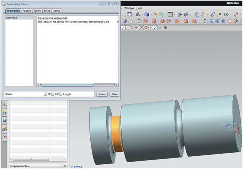
This platform is integrated with the NX Unigraphics CAD modeling software from Siemens and is currently actively used by GE Aviation. Figure 1Reference Rangarajan, Radhakrishnan, Moitra, Crapo and Robinson1 illustrates the automatic detection of a groove feature that has violated a manufacturability rule (the groove uses a nonstandard fillet and hence requires special tooling, which increases cost). The primary focus for this system was to develop automatic feature detection and manufacturability rules for complex machined parts; however, this same platform can be extended to other design and manufacturing domains.
Design for manufacturability system embedded in a computer-aided design (CAD) modeling software shows a groove feature being automatically detected and highlighted (orange) in a part design due to a manufacturability rule violation.Reference Rangarajan, Radhakrishnan, Moitra, Crapo and Robinson1

AM parameter development optimization
The development of novel high-temperature-capable, high-strength nickel (Ni) superalloys for laser powder bed fusion AM (LPBFAM) has proven to be challenging, primarily because of their susceptibility to microcracking.Reference Nie, Ojo and Li6 Significant efforts have gone into the development and optimization of machine and process parameters for these hard-to-process superalloys. The development of optimal build parameters and understanding the impact (both direct and indirect) on as-built part quality in a high-dimensional processing space is nontrivial. Process parameter development (PPD) in superalloy systems for LPBFAM can take many months to complete, leading to increased development costs and presenting a high barrier to entry for new materials in the additive marketplace. Therefore, an advanced framework utilizing probabilistic ML and intelligent sampling and optimization protocols, coupled with high-throughput printing, testing, and characterization tools to accelerate PPD for LPBFAM has been developed.Reference Dheeradhada, Chennimalai Kumar, Dial, Hanlon, Vinciquerra and Gupta7,Reference Dheeradhada, Chennimalai Kumar, Dial, Hanlon, Vinciquerra, Gupta and Grande8 This framework has been successfully demonstrated for high-strength nickel superalloys used in hot sections of aircraft engines.
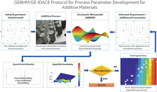
The framework consists of the GE Bayesian Hybrid Model (GEBHM)Reference Kumar, Subramaniyan and Wang9,Reference Kumar, Subramaniyan, Wang and Wiggs10 as the probabilistic ML technique, and the GE Intelligent Design and Analysis of Computer Experiments (GE-IDACE) as the intelligent sampling framework with optimization (Figure 2Reference Ling, Ghosh, Asher, Kristensen, Ryan and Wang11,Reference Kristensen, Ling, Asher and Wang12 ). An IDACE-based optimization integrated with BHM is an ideal approach for optimizing parameters for a multiobjective, high-dimensional LPBFAM process, requiring only a small number of test coupons and builds. GEBHM utilizes a Gaussian process to develop a predictive, data-driven modeling technique and is ideally suited for highly nonlinear responses in multiple dimensions. One key advantage of GEBHM is that in addition to predicting mean values of the model response, it can also provide us with the uncertainty in the model response. The initial model is built with key inputs such as laser power, scan speed, hatch spacing, and beam spot size, along with initial constraints and experimental results. Depending on the nature of the additive modality, other key factors may also be included in the GEBHM model.
Framework of the protocol outlining the process of using the GE Bayesian Hybrid Model (GEBHM) and the GE Intelligent Design and Analysis of Computer Experiments (GE-IDACE) in process parameter development for additive manufacturing.Reference Ling, Ghosh, Asher, Kristensen, Ryan and Wang11,Reference Kristensen, Ling, Asher and Wang12
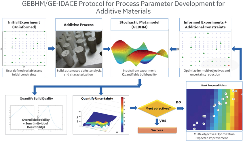
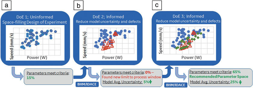
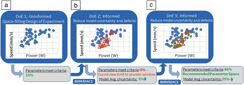
GE-IDACE utilizes the uncertainty information from the GEBHM model to iteratively identify new process parameter combinations for test coupons and builds. We have used GE-IDACE to address different objectives such as reducing overall model uncertainty or optimizing quantities of interest (QoI) such as porosity and mechanical properties. The objective gets better with each iteration, whether it is overall model quality or optimal value of QoI from the test coupons. Using these tools, LPBFAM PPD cycle time has been reduced by ∼4×, as shown in Figure 3,Reference Dheeradhada, Chennimalai Kumar, Dial, Hanlon, Vinciquerra and Gupta7,Reference Dheeradhada, Chennimalai Kumar, Dial, Hanlon, Vinciquerra, Gupta and Grande8 leading to significant savings in material cost, labor, and machine resources compared to traditional fractional design-of-experiment methods.
An example of GE Bayesian Hybrid Model/GE Intelligent Design and Analysis Computer Experiment (GEBHM/GE-IDACE)-based process parameter optimization for a hard-to-process superalloy. (a) The plot shows an initial design of experiments (DoE), which is space-filling and uninformed (no models are informing the DoE). The red triangles in the next figure are suggested by the GE-IDACE based on the GEBHM model built on the blue circle data set. Defects in the as-built part was measured after each DoE. (b) As noted, the DoE 2 reduced the model uncertainty by 5% but did not suggest any datapoints that met the target defect criteria. (c) In DoE 3, the green points are suggested by GE-IDACE based on the model built on the blue circles and red triangles. We have added more information through our GEBHM models that by DoE 3, we saw further reduction in model uncertainty (close to 25%) and also identified a parameter space window where more than 65% of the datapoints met the defect criteria, showing the power of the GE-IDACE methodology of performing experimental design.Reference Dheeradhada, Chennimalai Kumar, Dial, Hanlon, Vinciquerra and Gupta7,Reference Dheeradhada, Chennimalai Kumar, Dial, Hanlon, Vinciquerra, Gupta and Grande8
Recognizing the need for high-quality data, we developed automated image analysis routines to quantify LPBFAM-specific defects coupled with build designs. This enables us to obtain reliable, high-throughput data for the BHM model. The additive process/property response-surface developed with this protocol is highly valuable, especially when dealing with machine and process variations and machine-to-machine translation of process parameters.
Application of AI/ML in parameter development is still relatively new for AM. As with any new approach, there are barriers to acceptance. While other factors that can affect build quality have not been included in our studies, the applicability of the ML-based approach remains valid and can be extended to more complex problems. Another point to consider is that while our probabilistic ML framework uses GEBHM as the predictive model, it can be replaced with other ML techniques (that can also predict uncertainty) to account for different sizes of data and response types.
The protocol for PPD presented here may be applied to other additive modalities. Moreover, the GEBHM/GE-IDACE framework can be integrated into a more detailed hierarchical model capable of assessing more complex problems. Similar models have been used for several industrial applications, including combustion, material development, life prediction, controls, heat transfer, aerodynamics, vibration, acoustics, and mechanical design.Reference Ryan, Kristensen, Ling, Ghosh, Asher and Wang13,Reference Suzuki, Shen and Chennimalai Kumar14
Cold-spray AM and repair
Rapidly manufacturing or repairing complex parts is increasingly dependent on advanced robotics and AI/ML. We are combining ML and robotics to control how we apply materials in both manufacturing and repair processes. For example, we use ML to define toolpaths (physical path the spray nozzle moves through when applying material) during a “cold-spray” process to improve yield and reduce manufacturing time and cost.
Cold spray is a solid-state deposition process in which metallic powders are accelerated through a supersonic gas jet.Reference Ajdelsztajn, Schoenung, Jodoin and Kim15 The high-velocity deposition of particles onto a substrate causes them to deform plastically and adhere to the surface. Unlike thermal spray processes, the particles are not melted.Reference Ajdelsztajn, Lavernia, Jodoin, Richer and Sansoucy16 Thus, materials that tend to crack during rapid solidification, have high melting points, or are highly sensitive to oxygen are well-suited for cold spray because of the solid-state nature of the process. Another benefit is that the original microstructure of the feedstock powder is retained due to the absence of high temperatures during the process, opening the possibility of manufacturing amorphous and metastable alloys without critical cooling rate concerns. This promotes design freedom with chemistries not practicable with melting processes. The lack of oxidation and ability to form dense deposits make it an attractive alternative to more conventional AM techniques that involve melting and solidification. However, adaptation of cold spray from a traditional coating technique to an AM process requires the development of specific tools that can enable the buildup of complex shapes.
A customized robotic cold-spray system was developed with 12 degrees of freedom, enabling large, complex geometries to be manufactured (e.g., large aviation airfoils, cases, nozzles). The robotic arms need to work in exact coordination, making the toolpath generation a more complex problem to solve. We have incorporated advanced AI to guide their movements and allow them to adjust in situ to deliver high-quality builds of parts such as aviation airfoils. Further, we have demonstrated that the cold-spray deposition process may be improved by incorporating in situ three-dimensional scanning of the deposition surface to intelligently modify the toolpaths on the fly, completing the deposition process faster using less material.
The combination of AI/ML and robotics with cold spray opens the realm of impact additive technologies can have, including precision repair of large jet engine parts and beyond, as cold spray is not as confined in build volume and size as many other AM techniques.
Tool life modeling in machining
Tool wear in machining (milling, turning, and drilling) is the most important limitation to machining productivity and is defined as the loss of tool cutting-edge material during operation due to interaction with the workpiece material. Tool life is defined as the time required for tool wear to reach or exceed a predetermined wear limit (flank, notch, or crater depth).Reference Tlusty17 There have been many attempts at modeling and predicting tool life in the literature, using empirical models such as the Taylor-type tool life equation,Reference Taylor18,Reference Alauddin, El Baradie and Hashmi19 or physics-based models using temperature or finite element methods.Reference Usui, Shirakashi and Kitagawa20,Reference Xie, Schmidt, Schmidt and Biesinger21 The challenge in the practical implementation of the existing models is that they require extensive tool wear experimentation for calibrating model coefficients—an infeasible task in an industrial setting due to the large number of tool/material combinations. As a result, tool wear life is difficult to predict in practice.
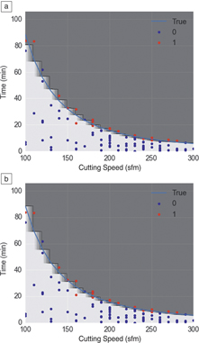
To address tool life prediction in an industrial setting, shop-floor production parts are treated as tool wear experiments. Tool wear data collected from the shop-floor are then used for modeling tool life. However, the fundamental challenge to using production shop-floor data is that tools are generally not used until failure—tool wear is only measured at the time of tool change, resulting in a single data point along a tool-wear versus cut-time curve. As a result, tool life prediction is treated as a ML classification problem as opposed to a regression problem. Two classes are defined—Class 0 represents a tool that has not failed and Class 1 represents a tool that has failed. Tool life is the classification decision boundary in time where the predicted tool class shifts from 0 to 1. Figure 4Reference Karandikar22 shows the tool life classification boundary using support vector machine radial basis function kernel (Figure 4a) and logistic classification (Figure 4b) methods.Reference Bishop23 The input data points for the ML model are also shown in Figure 4—blue and red dots represent data where the tool has not failed (Class 0) and has failed (Class 1), respectively. The white and gray regions denote cut time and spindle speed combinations where the prediction is Class 0 and Class 1, respectively. Figure 4 shows good agreement with the underlying tool life curve (blue line).
Tool life classification boundary using (a) support vector machine radial basis function kernel and (b) logistic classification. The blue and red dots are the input data points representing where the tool has not failed (Class 0) and has failed (Class 1), respectively. The white and gray regions denote cut time and spindle speed combinations where the prediction is Class 0 and Class 1, respectively. Both show good agreement with the blue line, the underlying tool life curve.Reference Karandikar22

There exists a cost tradeoff between cycle time and tool life in machining.Reference Karandikar and Kurfess24 The tool life model was enhanced to calculate machining cost as a function of machining parameters such that the optimal machining parameters minimize the total machining cost. This enabled an average 22% reduction in total machining costs across multiple parts at GE Aviation.
AI/ML can be effectively used to classify and model manufacturing process behaviors, which are difficult to predict using traditional methods. Subsequently, the ML models can be used to automate machining process parameter selection to optimize process performance. The practical challenge in implementing AI/ML to model process behaviors is the ability to generate data to train the model effectively. For modeling tool life, the tool wear data gathered from the shop floor is typically imbalanced (where the classes are not represented equally) and clustered around a few points. As a result, input data could be augmented by adding synthetic data based on either physics-based models or subject matter expertise.
AI/ML for inspection applications
Robust and accurate characterization of newly made and fielded (i.e., used in service) components is fundamental to modern industrial manufacturing processes. Here, we describe several applications where AI/ML is implemented for (1) inspection of new-make parts to ensure conformity with design specifications, (2) examination of fielded parts to assess wear, and (3) enhancing life prediction capabilities of components.
Material characterization using deep convolutional neural networks
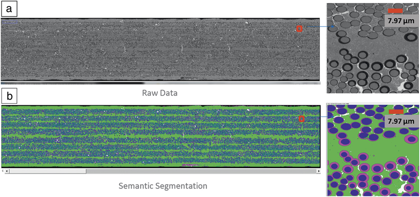
Microstructural inspection of ceramic matrix composite (CMC) materials that are used in aircraft engines is critical to ensure material performance and process consistency. Initial efforts to create an automated microstructure quantification algorithm used rules-based systems. However, these were unable to account for material variability (e.g., texture, shape, and intensity) and were sensitive to imaging parameters (e.g., lighting and stitching). Probabilistic and model-based methods effectively addressed some of the problems associated with material variability in small data sets, but were unable to scale to larger data sets. Therefore, we investigated a deep convolutional neural network approach for robust multimaterial characterization using thousands of images. This approach permits automated inspection and measurement of complex samples at scale. Parameters extracted from the characterized images are used to ensure process control and aid in understanding mechanical and physical properties of the composite material.
For CMC samples, we implemented a semantic segmentation model using U-Net architectures,Reference Ronneberger, Fischer, Brox, Navab, Hornegger, Wells and Frangi25 a type of deep neural network (DNN), to characterize features within optical photomicrographs of CMC parts. An expert first annotates relevant features (i.e., fiber, coating, and matrix) over regions of interest (ROIs) that are used to train the DNN model. The deep-learning library, MXNet,Reference Chen, Li, Li, Lin, Wang, Wang, Xiao, Xu, Zhang and Zhang26 was used, and the code was optimized for GPU (graphic processing unit) and Intel CPU (central processing unit) hardware. Creation of the training and test data sets was a time-consuming and challenging process. However, we were able to speed up data set creation by using the interactive “trainable weka segmentation” plug-in for ImageJ.Reference Arganda-Carreras, Kaynig, Rueden, Eliceiri, Schindelin, Cardona and Seung27 The weka plug-in allows a user to annotate (i.e., define) regions in an image belonging to a particular class/category and classify pixels using a collection of shallow (i.e., not a neural network) ML algorithms. The resulting trained model was able to attain 98% accuracy in assessing selected ROIs with test data sets.
Figure 5Reference Gugel, Brada, Santamaria-Pang, Wein and Wilson28 shows an example photomicrograph of a CMC part. Output images are shown at the bottom (Figure 5b) with results of the DNN segmentation highlighted as blue, magenta, green, and white, representing probability predictions for fibers, coating, matrix, and silicon, respectively. The results suggest the direct applicability of deep convolutional neural networks to the problem of robustly characterizing multiple materials in large data sets. The method is general, and we intend to apply it in different industrial inspection applications for inspection (e.g., scanning electron microscopy and computed tomography [CT] data sets) and material modeling.
Example of (a) a high-resolution optical photomicrograph of a ceramic matrix composite (CMC) part (right) with inset showing detail. (b) Semantic segmentation for the CMC part using the deep neural network. Results of the deep neural network segmentation are highlighted as blue, magenta, green, and white, representing probability predictions for fibers, coating, matrix, and silicon, respectively. (Inset) Higher magnification image showing more detail.Reference Gugel, Brada, Santamaria-Pang, Wein and Wilson28

Cooling hole drilling for aircraft engine blades
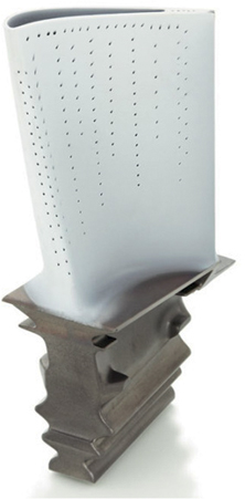
In modern aircraft engines, high-pressure turbine blades face increasingly elevated operating temperatures, and small cooling holes are critical to support blade function (Figure 6Reference Kellner29). GE Aviation shops use high-speed electrical discharge machining (EDM) to precisely drill large numbers of these cooling holes, with diameters usually less than 1 mm. Parts are inspected after drilling, and a rework process is initiated if a defective hole, usually a hole not drilled through, is found. The rework process is labor intensive due to reiterative loading–drilling–unloading–checking operation cycles. Therefore, a solution based on supervised deep learning was introduced to enable accurate on-site rework hole identification targeting, significantly improving rework efficiency.
A high-pressure turbine Ni-based superalloy blade with a thermal barrier coating and cooling holes less than 1 mm in diameter.Reference Kellner29 Courtesy of GE Aviation.

During production, machining signals (e.g., programmable logic controller running status, electrical discharging voltage and current, and electrode movement) from the EDM drilling process were collected. The stored data were labeled (i.e., clean through or rework) using engineering software tools. A DNN was created to take the EDM drilling process time series sensor signals as input. Common generalization techniques and a training-validation-test workflow were applied to avoid overfitting of the final model. The pretrained model was loaded into an online process monitoring and control systemReference Li, Wei, Xu, Gleason, Allison, Wessels and Zurawka30 to perform the on-site rework identification. This deep-learning approach also works with results from other historical data analytics to better handle drilling conditions and environment variations from part, electrode, and machine.
Compared to traditional rework identification approaches based on simple threshold-setting, the AI/ML-based solutions can better extract the engineers’ knowledge through a proper model training process. In practice, deep learning is much more robust for adapting to various process conditions with significantly fewer false alarms. During a preliminary production pilot test with an optimized pretrained model, nearly 100% of false alarms were removed successfully. We are continuously working to expand the solution coverage from rework identification to broader online process quality monitoring and control. Due to the similarity with industrial monitoring and control of various applications, the deep learning approach is expected to be applicable to many other shop machining processes (e.g., traditional turning, cutting, milling, welding, and laser materials processing).
Automated recognition of engine blade spallation and oxidation
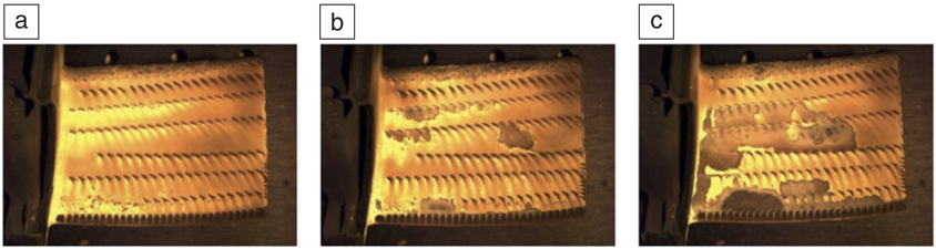
Surface material loss (i.e., spallation and oxidation) from an aircraft engine blade is a key indicator of (1) the condition of that individual component, and (2) the overall operation time left before an overhaul inspection of the engine. Therefore, it is important to have a consistent and robust way to quantify surface material loss. The traditional quantification method relies on a manual inspector giving a distress ranking for each individual component—typically a discrete value between 0 and 10, with higher values representing more serious material loss, as shown in Figure 7.Reference Bian, Lim and Zhou31 This evaluation process is subjective, based on the expertise of the individual inspector. Moreover, it compresses all visually observed information (e.g., different types of material loss in different locations) to a single number per component without any means to recover the rich contextual information for downstream analysis. A more robust method of evaluation would involve computer vision algorithms to reduce subjectivity and bias. To that end, we designed an automated recognition system to estimate the material loss. An original image of the component and a corresponding material loss map are both captured for downstream analysis.
Examples of aircraft engine Ni-based superalloy blades with different distress ranks, with (a) having low rank, (b) having moderate distress rank, and (c) having a high distress rank.Reference Bian, Lim and Zhou31

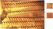
Recognizing spallation and oxidation regions is challenging, particularly due to the ineffectiveness of local features used during image analysis routines. In particular, color and texture information within a localized region are not sufficient to distinguish spalled regions between surfaces under different lighting conditions. This problem is evident in Figure 8,Reference Bian, Lim and Zhou31 which shows two local patches; one of which (the one on the left) shows spallation; both patches present similar visual patterns. In fact, inspectors generally rely on global context (e.g., boundaries) to identify a spall or oxidized region.
The challenge of using local features from optical imagery alone to identify spallation areas on an aircraft engine blade made of a Ni-based superalloy is evident in these two local patches (black boxes). The upper patch (from the left portion of the blade) shows spallation; the lower patch (from the right portion of the blade) does not; however, both patches present similar visual patterns. As a result, inspectors generally rely on global contexts (e.g., boundaries) to identify a spall or oxidized region. The yellow box shows examples of cooling holes, which often have a similar color as the spallation area.Reference Bian, Lim and Zhou31

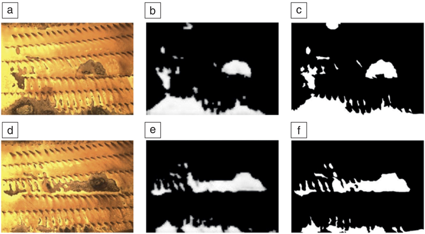
We developed a DNN framework, using a combination of low-level and high-level features to recognize spalled and oxidized regions.Reference Bian, Lim and Zhou31,Reference Diwinsky, Lim and Bian32 The architecture of the DNN was carefully designed to have a sufficient “receptive field” to actually “see” context and estimate whether a given region of interest has lost material. Figure 9Reference Bian, Lim and Zhou31 shows representative results from the DNN model. The model reduces the amount of time to reach a similar level of detailed inspection from about 5 min of manual work to less than 1 s. Further, manual inspectors typically condense all of the data down to a single score, losing much of the rich information observed in the output images.
Spallation segmentation examples of an aircraft engine blade from our deep neural network (DNN) model, with (a, d) original optical images, (b, e) output of our DNN model, and (c, f) annotation by the inspection experts, in which the white areas were hand-drawn by an inspector.Reference Bian, Lim and Zhou31

While these techniques have been developed and applied to aircraft engine blades, the approach could be used to detect material loss from components in other systems and in other industries as well.
Augmented reality-guided inspection
Manufacturing in heavy industries such as aviation, transportation, and oil and gas (O&G), requires the construction of complex, intellectual property-protected components that are manufactured separately and then assembled into larger machinery. These components (e.g., nozzles for gas turbines) require dozens of precise measurements during manufacturing. This precision translates into detailed quality inspections that must be performed on a continuous basis to ensure components remain within design specifications. Inspections are often performed manually due to the complexity of the components, which are (by nature) time-consuming and error-prone, resulting in productivity losses. Additionally, components are typically removed from the production line during inspection, leading to further losses resulting from equipment downtime.
After initial observations of the quality inspection process used during gas turbine nozzle assembly, we identified projection augmented reality (AR) systems as a potential candidate for reducing inspection time and errors. Projection AR systems rely on high-resolution industrial cameras at fixed locations to map component geometry and enable an AR experience. We designed and developed an intelligent user interface (IUI) using projection AR consisting of a mobile device, a large-screen monitor, sensor-driven measurement devices, and integrated software to superimpose visuals on an observed part, serving as cues to the inspector during the inspection process. In IUIs,Reference Maybury and Wahlster33 the intelligence can be embedded either in the interface device or within the system driving the interface. The former approach requires the intelligence to be localized to the interactions that the device is enabling, while the latter approach allows for system-wide application of the intelligence. Since quality inspection treats the component as a whole, we implemented the intelligence at the system level for this IUI.
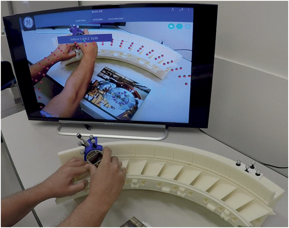
Our projection AR-based IUI solution to guide manual quality inspections transforms a quality inspection (QI) document for any given component into software that walks an engineer through the inspection process using AR while providing real-time feedback. In the example of the gas turbine nozzle assembly use-case mentioned, hundreds of measurements are required during inspection. The IUI, through the projection of green and red dots on a live feed of the nozzle, indicates the precise location for the measurements: a green dot indicates that a measurement has already been taken, and a red dot is indicative of a measurement to be taken. The system-level software driving the IUI automatically captures the measurements, applying them to models that indicate whether the part conforms to design requirements, as shown in Figure 10.Reference Castellanos34 In the case of nonconformance, the user is alerted in real time. Tests of this system performed at an O&G production facility demonstrated a considerable reduction in inspection time—reducing inspections from 8 h to under 1 h.Reference Castellanos34
Example of augmented reality-guided inspection with visual markers guiding the manual inspection of a high-speed power turbine stage 2 nozzle. Red dots on the screen specify locations on the part where a measurement is to be taken.Reference Castellanos34 Courtesy of GE Research.

Our approach is unique in that it uses both the CAD geometry of a complex part and the associated QI document as input parameters, resulting in an application that significantly reduces both errors and inspection time.Reference Castellanos34 One of the biggest challenges was creating unique geometric markers attached to the component so that the AR system could identify and map the CAD geometry to the precise measurement locations specified in the QI document; the markers could not interfere with the inspection locations, but had to remain connected to the component at all times to enable the AR experience.
This projection AR-based approach may be applied to a variety of manufacturing operations that require inspections of components with complex geometries. The solution can be applied during the design and construction of new components or to existing in-use components so long as the CAD geometry for those components is well documented.
Surface stress estimation for low-cycle fatigue prediction
The effect of surface roughness on low-cycle fatigue (LCF) behavior of metals and alloys has been studied for decades.Reference Kawamoto, Nishioka, Inui and Tsuchiya35 Surface preparation and machining techniques that reduce surface roughness, and those that leave the surface in a state of residual compression, have successfully been employed to extend fatigue lives in components subjected to cyclic stresses. While the same methodologies can generally be applied to external surfaces of additively manufactured components, they cannot be applied to the internal “as-built” surfaces of complex parts. Therefore, it is critical to understand how the surface characteristics of additively manufactured materials affect material properties.
In cases where LCF performance is a design requirement, surface roughness has traditionally been accounted for empirically with correlations to crack initiation life and effects on the endurance limit (highest stress amplitude at which a material can withstand indefinite cyclic loading without failing in fatigue).Reference Novovic, Dewes, Aspinwall, Voice and Bowen36 More recently, full finite-element (FE) calculations of surface topography have been used to correlate stress risers associated with microscopic surface asperities to fatigue life.Reference As, Skallerud, Tveiten and Holme37 The computing resources required to make such calculations are considerable and, given the complexity of additively manufactured surfaces, have become time- and numerically intensive, to the point of being prohibitive. Supervised ML tools have the potential to significantly reduce the computational expense associated with these calculations.
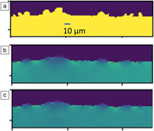
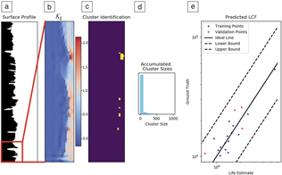
Using data sets from additively manufactured test coupons, we trained a convolutional neural network ([CNN], a biologically inspired artificial neural network that uses convolutional kernels across interconnected layers that can be trained to learn visual imagery data) to predict surface stresses based on measured surface roughness. Data sets were collected using nano-CT with a voxel resolution of ∼3 μm per side (Figure 11a).Reference Hanlon, Reimann, Soare, Singhal, Grande, Edgar, Aggour and Vinciquerra38 CT data set surfaces were meshed, and FE calculations were run to assess stress concentrations associated with surface asperities (Figure 11b). The CNN was trained on a series of FE models designed to mimic the range of surface asperity geometries expected in a part. Figure 11Reference Hanlon, Reimann, Soare, Singhal, Grande, Edgar, Aggour and Vinciquerra38 compares the first-principal stress calculated using the time-intensive FE model (Figure 11b) with the stress as predicted by the deep physics algorithm (Figure 11c). The error between these stress predictions is <5%, and the CNN was able to complete the calculations in a fraction of the time required for FE simulations (i.e., seconds versus hours).
Surface topography and stress concentrations of an additively manufactured cylindrical test coupon. (a) Actual surface topography as measured via nano-computed tomography with a pixel resolution of ∼3 μm. (b) Finite element calculation of stress concentrations associated with surface asperities. (c) Deep physics prediction of stress concentrations associated with surface asperities.Reference Hanlon, Reimann, Soare, Singhal, Grande, Edgar, Aggour and Vinciquerra38

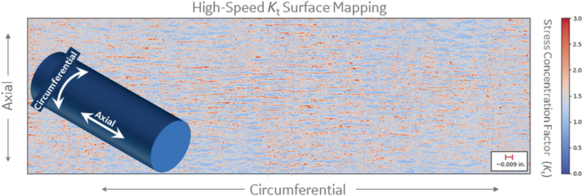
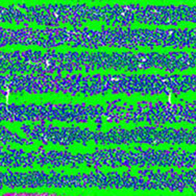
Figure 12Reference Hanlon, Reimann, Soare, Singhal, Grande, Edgar, Aggour and Vinciquerra38 illustrates application of the “deep physics” algorithm over a large area scan of a material to produce a stress concentration map that would be impractical to obtain using FE simulations. Further, subsequent models relate the stressed volume adjacent to surface asperity features to overall fatigue life (Figure 13Reference Hanlon, Reimann, Soare, Singhal, Grande, Edgar, Aggour and Vinciquerra38). Fidelity of life predictions requires the application of the method over many tens of conventional fatigue specimens, thus AI/ML methods can reduce analysis times from months to days relative to standard FE calculations over the same volume of material, bringing obvious cost savings to the design cycle of a part. Our methodology can also be considered, conceptually, as an inline quality control mechanism during production.
Large-area stress concentration map taken from the gage section of an additively manufactured CoCr low-cycle fatigue test specimen. Patterns indicate an unfavorable distribution of surface roughness with the current set of build parameters.Reference Hanlon, Reimann, Soare, Singhal, Grande, Edgar, Aggour and Vinciquerra38

Process of converting (a) images of surface roughness to (b) stress concentration profiles. (c) Areas containing neighboring pixels with stress concentration factor, K t, greater than 2.5 are grouped into clusters (yellow), with cluster sizes tabulated in (d). (e) Clusters of pixels with elevated K t levels are then quantified to simulate stressed volumes, which can theoretically be applied to augment more traditional lifing strategies. Note: LCF, low-cycle fatigue.Reference Hanlon, Reimann, Soare, Singhal, Grande, Edgar, Aggour and Vinciquerra38

Federated big data storage and analytics
Data are the lifeblood of the analytics underpinning these advances in AI/ML for manufacturing and inspection. As a result, we expend considerable effort to efficiently capture, store, and make available a plethora of diverse data types. For example, in the AM space, a substantial and structurally diverse amount of data is generated and used throughout the AM life cycle. To deliver on the promise of AM, we have developed novel strategies to intelligently collect, store, link, and analyze these data.
We have built a knowledge-driven federated, multimodal big data storage and analytics platform to address this need. Our strategy is to capture each different type of data in a repository optimized for that data format, rather than force-fitting different types of data into a monolithic data warehouse or, alternately, keeping all of the data in a data format-independent (NoSQL) store (thereby ignoring the structure inherent in much of the data). By keeping each type of data in a repository most conducive to each format, we minimize the storage footprint and maximize the query performance for each individual data type. However, this presents a challenge with respect to linking data across the different repositories.
Our solution to this challenge utilizes a formal, English-like semantic language to model the data structure and relationships across the systems.2,Reference Crapo and Moitra3 Beyond modeling the relationships between the data stored within and across the different repositories, we further model the underlying data stores, including capturing metadata on how to query and interact with each repository.Reference Williams, Cuddihy, McHugh, Aggour, Menon, Gustafson and Healy39,Reference McHugh, Cuddihy, Williams, Aggour, Kumar and Mulwad40 A software platform sitting atop the data stores and driven by the semantic model provides a set of services and application programming interfaces (APIs) permitting users to interact with and explore the data without having to know where the data are physically housed or how to query it. Instead, our system provides a single logical interface on top of a plethora of diverse, distributed data repositories. The platform further enables the execution of analytics directly within the data storage infrastructure to minimize data movement and accelerate analytic runtime.
This platform is built using the GE-developed and partially open-sourced Semantics Toolkit (SemTK), a framework that provides a library of services, APIs, and a user interface, dramatically simplifying the creation and utilization of knowledge graphs and knowledge-driven applications.Reference Cuddihy, McHugh, Williams, Mulwad and Aggour41,42 Further, we use SADL to author the semantic models in a formal, structured English-like language.2,Reference Crapo and Moitra3
While this federated, multimodal big data storage and analytics platform was built with a focus in the AM domain, the underlying capabilities and potential benefits are not limited to AM. A semantic model could be similarly defined for most any data-intensive domain, and the platform could be rapidly repurposed to achieve the same effect of capturing and intelligently linking diverse data.
AI/ML and the future of manufacturing
In recent years, computational models have been developed to predict materials microstructures and properties for traditional manufacturing processes by means of theoretical and physics-based principles. However, as performance specifications tighten and competition demands the faster introduction of new products, the importance of AI/ML will only grow. Novel synthesis approaches to extract and combine knowledge derived from multiple sources (e.g., proprietary and public structured experimental data, unstructured publications, and tacit human expert knowledge) and fuse these with diverse physics-based models operating at different micro- and macroscales, may offer a framework to generate explanatory AI of manufacturing processes.
Alloy design and development
Data-driven property models created using AI/ML are particularly useful in predicting physical properties with relatively simple dependence on composition (e.g., coefficient of thermal expansion, density, and modulus). These models are also useful for predicting highly nonlinear properties too complex for physics-based models to achieve with a desired accuracy (e.g., creep and fatigue resistance).
Suzuki et al.Reference Suzuki, Shen and Chennimalai Kumar14 described examples of methodologies used to predict properties and discover new alloys with the desired combination of properties, using Ni-based superalloys as a model system. However, as the authors point out, significant challenges arise because input data sets are often not ideal for ML; many are relatively small (e.g., several hundred data points or fewer) and insufficiently sampled within the parameter space (e.g., using empirical decisions guided by experts rather than factorial designs). Noise and scatter within data sets may also be an issue depending on the measurement methods used. Despite the challenges, AI/ML models were able to reduce the cycle time for alloy design and the design of new materials for next-generation high-performance products (e.g., see the “AM parameter development optimization” section in this article). Future developments in methodologies used to preprocess nonideal data sets, identify gaps within parameter spaces, and enhance material property databases (e.g., high-throughput screening) will aid AI/ML adoption for alloy design.
Inverse material design
The use of theoretical and physics-based models are limited in the AM design space due to the complex interactions between materials and processes. As AM grows, AI/ML will become more important to deal with the complex interactions between the material and additive platform, CAD model design and build orientation, and build and post-processing parameters. These parameters must be optimized for each material, often varying across AM machine make and model, even within a single platform. Typically, optimization of these parameters entails a brute-force, trial-and-error approach, whereby large volumes of material are additively built and tested to establish locally optimal parameter sets. These iterative design and optimization loops are expensive, potentially taking multiple years to complete unless alternative methods are developed (see the previous “AM parameter development optimization” section in this article).
The desired result should be a compilation of microstructures and material properties across materials, machines, and processing parameters otherwise inconceivable via state-of-the-art techniques. Revolutionary AI tools are required to not only provide desired predictive capability, but also explain their reasoning processes for predictions and develop hypotheses from existing data. Once such an AI has been built to accurately predict microstructure and properties, these models can be used to develop an “inverse” approach to AM material design and process parameter selection, where part performance characteristics are specified, and the AI predicts optimal material/machine/process–parameter combinations to achieve target performance. Since inverse relationships are almost always one-to-many, a good inverse model should be able to identify multiple solutions so that the user has flexibility to select the material microstructure that can be attained in the easiest, fastest, and most cost-effective manner (i.e., high-quality and high build productivity).
We are leveraging our federated multimodal big data storage and analytics platform as a foundation upon which we are building AI/ML tools to enable the inverse design of additive materials. An inverse approach would exponentially lower the barrier of adoption for AM, particularly in applications where high-performance materials are mission critical. Moreover, the cost savings and performance enhancements are revolutionary, potentially reducing years of costly development time to perhaps weeks.
Fast topology optimization
Topology optimization is an important step in designing structures to be produced via AM. Multiphysics topology optimization has previously been used to design multiple parts. A typical topology design optimization process consists of (1) building multiphysics analysis models; including combining fluid, thermal, and structural physics; (2) performing model validations; (3) executing optimization runs; and (4) creating concept designs based on the optimized topology.
While topology optimization can significantly reduce design cycle time, it generally takes six months to two years to develop an optimized design, depending on the part’s complexity. What is needed is an automated, intelligent, fast design tool to accelerate topology optimization as well as replicate and replace human-in-the-loop interpretation of the topology results. Such a tool could reduce the design cycle time to months or even weeks.
Specifically, we have identified three candidate areas where AI/ML could transform the design optimization step into an automated, intelligent, and efficient process:
1. Deep learning could accelerate convergence of partial and intermediate solutions within a single iteration of topology optimization.
2. Deep active learning could accelerate the search for optimal topologies across multiple iterations while intelligently exercising exploration versus exploitation tradeoffs.
3. Knowledge-based assistants could emulate expert subjectivity in translating the optimal topology to a concept design, by suitable representation of relevant metadata across an array of historical expert choices.
Summary
We have been harnessing AI/ML to accelerate and improve manufacturing and inspection in a multitude of ways at GE Research. AI/ML is driving innovation in subtractive manufacturing, AM and repair, and material and asset inspections through advanced technologies such as knowledge representation and reasoning, probabilistic modeling, deep learning, computer vision, augmented reality, and knowledge-driven data management, to name a few. While we are already applying AI/ML to a wide variety of challenges in manufacturing and inspection (only a sampling of which have been previously described), going forward over time, we believe AI/ML will have an even greater impact on our business, our industries, and our world.

Kareem S. Aggour is a principal scientist in the AI Knowledge and Big Data Group at GE Research. He received his PhD degree in computer science from Rensselaer Polytechnic Institute. Aggour can be reached by email at aggour@ge.com.

Vipul K. Gupta is a lead scientist in the Structural Materials Group at GE Research. He received his PhD degree in materials science and engineering from the University of Virginia. Gupta can be reached by email at vipul.k.gupta@ge.com.

Daniel Ruscitto is a senior scientist in the Materials Characterization Group at GE Research. He received his PhD degree in geological sciences from the University of Oregon. Ruscitto can be reached by email at ruscitto@ge.com.

Leonardo Ajdelsztajn is a principal scientist in the Structural Materials Group at GE Research. He received his PhD degree in materials science from the Federal University of Rio de Janeiro, Brazil. Ajdelsztajn can be reached by email at ajdelsztajn@ge.com.

Xiao Bian is a Senior scientist in the AI and Computer Vision Group at GE Research. He received his PhD degree in electrical engineering from North Carolina State University. Bian can be reached by email at xiao.bian@ge.com.

Kristen H. Brosnan is the technology manager in the Structural Materials Group at GE Research. She received her PhD degree in materials science and engineering from The Pennsylvania State University. Brosnan can be reached by email at brosnan@ge.com.

Natarajan Chennimalai Kumar is a senior engineer in the Mechanics and Design Group at GE Research. He received his PhD degree in mechanical engineering from the University of Illinois at Urbana-Champaign. Kumar can be reached by email at kumarn@ge.com.

Voramon Dheeradhada is a senior materials engineer in the Structural Materials Group at GE Research. She received her PhD degree in materials science from Purdue University, where she was also recently awarded an Outstanding Materials Engineer Award. Dheeradhada can be reached by email at dheeradh@research.ge.com.

Timothy Hanlon is a principal scientist in the Structural Materials Group at GE Research. He received his PhD degree in materials science from the Massachusetts Institute of Technology. Hanlon can be reached by email at hanlon@research.ge.com.

Naresh Iyer is a principal scientist in the AI and Machine Learning Group at GE Research. He received his PhD degree in artificial intelligence from The Ohio State University. Iyer can be reached by email at iyerna@ge.com.

Jaydeep Karandikar is a lead engineer in the Structural Materials—Manufacturing Group at GE Research. He received his PhD degree in mechanical engineering from the University of North Carolina at Charlotte. Karandikar can be reached by email at jaydeep.karandikar@ge.com.

Peng Li is a senior principal scientist in the Structural Materials—Manufacturing Group at GE Research. He received his PhD degree in condensed-matter physics from the University of Science and Technology of China. Li can be reached by email at peng.lee@ge.com.

Abha Moitra is a principal scientist in the AI Knowledge and Big Data Group at GE Research. She received her PhD degree in computer science from the Tata Institute of Fundamental Research, India. Moitra can be reached by email at moitraa@ge.com.

Johan Reimann is a senior scientist in the AI and Machine Learning Group at GE Research. He received his PhD degree in electrical and computer engineering from the Georgia Institute of Technology. Reimann can be reached by email at reimann@ge.com.

Dean M. Robinson is a principal engineer in the Additive Manufacturing Technologies Group at GE Research. He received his PhD degree in mechanical engineering from Cornell University. Robinson can be reached by email at robinsondm@ge.com.

Alberto Santamaria-Pang is a principal scientist in the AI and Computer Vision Group at GE Research. He received his PhD degree in computer science from the University of Houston. Santamaria-Pang can be reached by email at santamar@ge.com.

Chen Shen is a senior scientist in the Structural Materials Group at GE Research. He received his PhD degree in materials science and engineering from The Ohio State University. Shen can be reached by email at chens@ge.com.

Monica A. Soare is a senior scientist in the Structural Materials Group at GE Research. She received her PhD degree in mechanical engineering from Rensselaer Polytechnic Institute. Soare can be reached by email at soare@ge.com.

Changjie Sun is a principal engineer in the Mechanics and Design Group at GE Research. He received his PhD degree in mechanical engineering from Kansas State University. Sun can be reached by email at sunc@ge.com.

Akane Suzuki is a principal engineer in the Structural Materials Group at GE Research. She received her PhD degree in metallurgy and ceramics science from the Tokyo Institute of Technology, Japan. Suzuki can be reached by email at suzukia@ge.com.

Raju Venkataramana is the technology manager for human computer interaction in the AI Group at GE Research. He received his PhD degree in computer science and engineering from the University of South Florida. Venkataramana can be reached by email at venkataramana@ge.com.

Joseph Vinciquerra is a senior principal engineer and the Additive Platform Leader at GE Research. He received his MS degree in mechanical engineering from Syracuse University, and his MBA degree from Rensselaer Polytechnic Institute. Vinciquerra can be reached by email at joseph.vinciquerra@ge.com.