I. INTRODUCTION
Three-dimensional (3D) helical materials have attracted worldwide attention due to their peculiar morphologies, unique properties and interesting growth mechanisms.Reference Cervantes-Sodi, Vilatela, Jimenez-Rodriguez, Reyes-Gutierrez, Rosas-Melendez, Iniguez-Rabago, Ballesteros-Villarreal, Palacios, Reiband and Terrones1–Reference Gao, Ding, Mai, Hughes, Lao and Wang6 Carbon nanocoils (CNCs), as one of the important 3D materials, have attracted much attention due to their excellent mechanical and electromagnetic properties. To date, several kinds of carbon coils have been synthesized, such as multiwall CNCs (MWCNCs),Reference Lau, Lu and Hui4,Reference Kanada, Pan, Akita, Okazaki, Hirahara and Nakayama7 coiled carbon nanofibers (CCNFs),Reference Jian, Jiang, Zhou, Zeng, Lu, Wang, Zhu, Gou, Wang, Hui and Yang8 and conventional CNCs.Reference Hayashida, Pan and Nakayama9,Reference Li, Pan, Liu and Yu10 We distinguish a MWCNC from a CCNF in that the former comprises single and multiwall CNTs while the latter is a solid amorphous structure. Among the two kinds of materials mentioned above, the conventional CNCs are composed of several coiled hollow tubules with low crystallinity. It is reported that most CNCs with a coil diameter less than 50 nm are MWCNCs. These MWCNCs are expected to have higher electrical conductivity and stronger mechanical properties than the conventional CNCs.Reference Hayashida, Pan and Nakayama9,Reference Chen, Zhang, Dikin, Ding, Ruoff, Pan and Nakayama11,Reference Treacy, Ebbesen and Gibson12 These excellent properties as well as their unique helical shape make MWCNCs suitable for many applications. On the microscopic scale, MWCNCs are expected to be used as nano-sized springs, and units in micro/nano electromechanical systems.Reference Volodin, Buntinx, Ahlskog, Fonseca, Nagy and Van Haesendonck13 On the macroscopic scale, MWCNCs can be used in high-performance composite films with high conductivity, good elasticity and toughness.Reference Li, Lau and Yin14 Meanwhile due to their helical structure, MWCNCs are also considered as good materials for highly efficient electromagnetic wave absorbers.Reference Zhao and Shen15
The synthesis of conventional CNCs including their structure, formation, and growth mechanism has been reported in many articles.Reference Lau, Lu and Hui4,Reference Li, Pan, Liu and Yu10,Reference Li and Pan16–Reference Kuzuya, In-Hwang, Hirako, Hishikawa and Motojima19 So far, many research groups have synthesized CNCs with large coil diameters (greater than 50 nm) in large quantities.Reference Li and Pan16–Reference Pan, Zhang and Nakayama18,Reference Su and Chang20–Reference Pan, Hayashida and Nakayama22 However, still there has been no breakthrough in the preparation techniques for growing MWCNCs with small coil diameters (less than 50 nm). The main reasons are that the growth mechanism for the MWCNCs is not clear and the optimum catalysts have not been found. Therefore, the growth of MWCNCs can’t be effectively controlled, leading to their lower production rate.
In general, MWCNCs are synthesized by catalytic chemical vapor deposition (CVD) using hydrocarbons as reaction gas and transition metals as catalysts.Reference Kanada, Pan, Akita, Okazaki, Hirahara and Nakayama7,Reference Liu and Harris23–Reference Zhang, Zhang, Bernaerts, Vantendeloo, Amelinckx, Vanlanduyt, Ivanov, Nagy, Lambin and Lucas25 The first experimental observation of the production of MWCNCs was done in 1994, when Zhang and Amelinckx et al.Reference Ivanov, Nagy, Lambin, Lucas, Zhang, Zhang, Bernaerts, Vantendeloo, Amelinckx and Vanlanduyt26,Reference Amelinckx, Zhang, Bernaerts, Zhang, Ivanov and Nagy27 synthesized MWCNCs by catalytic deposition of acetylene over a silica-supported Co catalyst in a CVD system at 700 °C. Similarly, Lu et al.Reference Lu, Lau, Xu and Li28 have prepared MWCNCs by catalytic CVD on finely dispersed Co nanoparticles supported on silica gel under reduced pressure and relatively low gas flow rates. Tsuchiya et al.Reference Tsuchiya and Ogino29 have reported a method to prepare MWCNCs using a combination of Al2O3-supported Ni catalyst and alcohol CVD. They found that when a Ni–Fe or Ni–Co alloy catalyst was used, the yield of CNCs decreased. Recently, Yokota et al.Reference Yokota, Suda, Takikawa, Ue, Shimizu and Umeda30 have synthesized MWCNCs with a filament diameter less than 50 nm by CVD using zeolite-supported Fe–Sn catalysts. It was found that more than 90% of the CNCs obtained were MWCNCs, and the remaining were columnar CNCs without a hollow structure. It is noted that in the methods mentioned above, the catalyst supports (silica, Al2O3, and zeolite) were needed for preparing catalyst particles, which is considered to be beneficial for increasing the formation of MWCNCs. In a different approach, Pan et al.Reference Kanada, Pan, Akita, Okazaki, Hirahara and Nakayama7 have synthesized MWCNCs by thermal CVD using a co-deposited thin film consisting of Fe and Sn as catalysts and they found that Sn plays a crucial role in the growth of MWCNCs. Similarly, Chen et al.Reference Chen, Yang, Motojima and Ichihara31 have synthesized twisted carbon nano-ribbons by the catalytic pyrolysis of acetylene using Fe alloy (Fe74Cr1Ni8 or Fe71Cr1Ni8Mo3) films as a catalyst, prepared by sputter coating on the glass substrates.
In this study, we have used ion sputtering to prepare Fe films. As a result, we successfully synthesized MWCNCs, using only Fe films as the catalyst. We also have investigated the effects of substrates and film thickness on the growth of the carbon products. In addition, we have proposed a model for the growth of MWCNCs which is helpful for the interpretation of the growth mechanism of MWCNCs.
II. EXPERIMENTAL
A. CNC synthesis
For indium tin oxide (ITO) substrates, ITO layered glass substrates were used and the thickness of the ITO film on the glass substrate was approximately 100 nm. Whereas, for SiO2 substrate, SiO2 layered p-type Si(100) substrates were used, where the thickness of the SiO2 film on the Si substrate was approximately 100 nm. Fe films deposited on ITO or SiO2 substrates were selected as catalysts for the growth of CNCs. The Fe films were prepared by ion sputtering in a vacuum chamber with a working pressure of 6 Pa. The distance between the substrate and the Fe target was kept at 5 cm and the discharge current was 10 mA. The thicknesses of Fe films were controlled by changing the sputtering time. The samples were calcined in air at 700 °C for 30 min and allowed to cool to room temperature with a cooling rate of 35 °C/min. Then the samples were placed in the center of a CVD furnace and heated from room temperature to 700 °C under an Ar atmosphere with a flow rate of 260 sccm. CNCs were synthesized in a thermal CVD system at 700 °C for 30 min by introducing acetylene and Ar gases with flow rates of 15 and 245 sccm, respectively. In addition, we have investigated the morphological changes of Fe film catalysts on SiO2 substrate in the initial stage of MWCNC synthesis by introducing acetylene and Ar gases with flow rates of 1 and 260 sccm for 0–2 s.
B. Characterization
The catalyst film thickness was measured by a surface profilometer (NewView5022, ZYGO, Middlefield, CT) and an optical fiber spectrometer (Maya2000-Pro, Ocean Optics, Dunedin, FL). The morphology and structure of synthesized carbon products were analyzed by a scanning electron microscope (SEM; Nova NanoSEM 450, FEI, Hillsboro, OR), transmission electron microscope (TEM; JEM-2000EX, Tokyo, Japan), Raman spectrometer (Renishaw inVia plus, Renishaw, Gloucetershire, UK) and atomic force microscope (AFM; Agilent PicoPlus II, Agilent, Santa Clara, CA).
III. RESULTS AND DISCUSSION
A. Growth of CNCs on Fe film coated ITO substrates
It is considered that the size, structure and composition of catalyst particles are crucial for synthesizing CNCs with controlled filament diameter and crystalline structure. The smaller the catalyst particles (i.e., the thinner the catalyst films), the thinner would be the synthesized CNCs. Herein, our focus is to investigate the effect of Fe catalyst film thickness on the growth of the CNCs.
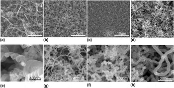
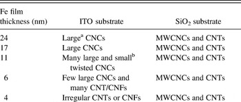
Firstly, Fe films with thicknesses varying from 2 to 24 nm were deposited on the ITO substrates by the ion sputtering method. Carbon materials were then synthesized using Fe film coated ITO substrates as above mentioned, with acetylene flow rate of 15 sccm, which are shown by SEM images in Fig. 1. It is found that the Fe film thickness significantly affects the morphologies of the grown carbon products. The properties of carbon products prepared using Fe films with different thicknesses are summarized in Table I. High yield CNCs with diameters larger than 100 nm can be grown on a 24-nm thick Fe film coated ITO substrate [Figs. 1(a) and 1(e)]. It is interesting to note that when the Fe film thickness is decreased to 11 nm, CNCs with large diameters and small twisted CNCs are observed in the synthesized products [Figs. 1(b) and 1(f)]. By further decreasing the thickness of the Fe film, the quantity ratio of large CNCs continues to be reduced in the carbon product. Figures 1(c) and 1(g) show the carbon deposits obtained using a 6-nm thick Fe film coated ITO catalyst, where only a few large CNCs can be observed. However, when the Fe film thickness is decreased to less than 4 nm, no CNC but only some irregular CNTs or CNFs with a uniform diameter of approximately 30 nm are grown [Figs. 1(d) and 1(h)]. From the above results we can conclude that the thick Fe film (24 nm) deposited on ITO substrates leads to the growth of CNCs with large diameters, whereas small twisted CNCs can be produced when decreasing the Fe film thickness (11 nm), but only irregular CNTs or CNFs are obtained by using much thinner Fe films (less than 4 nm). The cause for these phenomena is considered to be due to the changes of the Fe/ITO molar ratio for catalysts when using Fe films with different thicknesses. Though CNCs with controlled diameters could be synthesized using Fe film coated ITO catalysts to some extent, however, it is not an effective method for synthesizing thin CNCs, especially for MWCNCs.
Low and high magnified SEM images of the carbon deposits synthesized at 700 °C using Fe-coated ITO catalysts by ion sputtering with different Fe film thicknesses: (a) and (e) 24 nm, (b) and (f) 11 nm, (c) and (g) 6 nm, and (d) and (h) 4 nm.

Properties of carbon deposits using Fe films on different substrates.

a CNC with a coil diameter larger than 100 nm.
b CNC with a coil diameter smaller than 100 nm.
It is known that the choice of underlayer (substrate) material has been proven to be extremely crucial for CNT synthesis. For example, CNTs have been grown on insulating substrates (SiO2, MgO, Al2O3, etc) by many researchers.Reference Wen, Tian, Qian, Hu, Yun, Cao and Wei32–Reference Wei, Eres, Merkulov and Lowndes38 Growing CNTs on metallic underlayers is more difficult because alloying and increased mobilities hinder CNT nucleation and growth. Similarly, the choice of substrate or catalyst support is considered to play an important role in the growth of CNCs or MWCNCs.
B. Growth of MWCNCs on Fe film coated SiO2 substrates
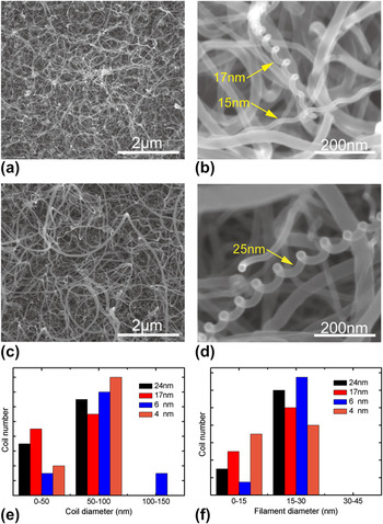
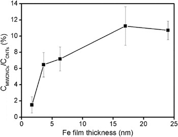
Instead of ITO glass, SiO2 was selected as the substrate to deposit Fe films. Similar to the above section, Fe films with different thicknesses were deposited on SiO2 substrates by ion sputtering. Figure S1 shows the x-ray energy dispersive (EDX) spectrum of the Fe film with a thickness of 24 nm deposited on the SiO2 substrate, where only the Fe element is observed, (Si and O are mainly originated from the SiO2 substrate). Figures 2 and S2 show the SEM images of carbon materials grown with an acetylene flow rate of 15 sccm at 700 °C for 30 min and using Fe films (with different thickness) deposited on SiO2 substrates as catalysts. In Fig. 2(a), a 24-nm thick Fe film coated SiO2 substrate is covered by high yield CVD grown CNTs with a variation in filament diameter. A careful observation reveals that some MWCNCs are also produced in the carbon deposits, which indicates that single Fe film could be used as the catalysts for the growth of the MWCNCs. Figure 2(b) shows an enlarged SEM image of two typical MWCNCs in Fig. 2(a). The coil diameters of the grown MWCNCs are measured to be less than 100 nm and the filament diameters of most MWCNCs grown under this condition are less than 30 nm [shown in Figs. 2(e) and 2(f)], which are much thinner than for conventional CNCs produced using Fe film coated ITO catalysts. For thinner Fe film catalysts on SiO2 substrates, the coil diameter and filament diameter distributions of the grown MWCNCs are similar to those obtained using the thick Fe films, as shown in Figs. 2(c)–2(f) and S2. However, the yield percentage of MWCNCs is decreased rapidly with a lower thickness of the Fe film, as shown in Fig. 3. It is noted that the numbers of both MWCNCs and CNTs are very low when the Fe film thickness is decreased to 2 nm. This suggests that the choice of an appropriate Fe film thickness is necessary for the efficient growth of MWCNCs, which is similar to that of CNT growth.Reference Hofmann, Cantoro, Kleinsorge, Casiraghi, Parvez, Robertson and Ducati34,Reference Wei, Eres, Merkulov and Lowndes38
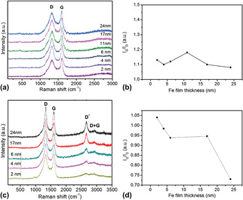
Raman spectra of carbon deposits prepared using Fe films deposited on (a) ITO and (c) SiO2 substrates with different film thicknesses. (b) and (d) show the corresponding variation of IG/ID ratio with Fe film thickness shown in (a) and (c).

Typical SEM images of the carbon deposits synthesized at 700 °C using Fe film catalysts deposited on SiO2 substrates by ion sputtering. (a) 24 nm and (c) 6 nm. (b) and (d) are the corresponding enlarged images of MWCNCs in (a) and (c). (e) and (f) show distributions of coil diameters and filament diameters of MWCNCs prepared using Fe films deposited on SiO2 substrates with different film thicknesses.

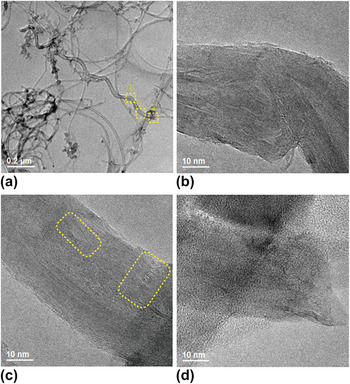
Figure 4 shows the typical TEM images of a CNC synthesized by an Fe film catalyst with a thickness of 17 nm on an SiO2 substrate. It is observed in Fig. 4(a) that the CNC is hollow in structure, which is composed of a helical CNT with a coil and filament diameter of 70 and 36 nm, respectively. The enlarged TEM images shown in Figs. 4(b)–4(d) indicate that many defects exist in the graphitic layers of MWCNCs, either in the straight parts or in the bending parts, which can be clearly seen in two square areas of Fig. 4(c). However, these defects are rarely observed in the straight CNTs that are grown under the same condition (not shown here), indicating a high degree of graphitization of CNTs.
Dependence of the MWCNCs and CNTs ratio with Fe film thickness.

The graphitization degree of carbon deposits prepared on Fe film coated ITO and SiO2 substrates are examined by Raman spectra, as shown in Fig. 5. For carbon deposits grown on ITO substrates, two main peaks are observed in the Raman spectra, one is around 1322 cm−1 known as D-band originated from structural defects or disorders in carbon nanomaterials, and the other is around 1595 cm−1 known as G-band originated from graphite structures [Fig. 5(a)]. It is observed in Fig. 5(b) that the decrease of Fe film thickness has little effect on the IG/ID ratio (has a little change, approximately 1.1–1.2); this indicates that carbon materials produced including CNCs and irregular CNTs/CNFs by Fe film coated ITO catalysts have the similar nanostructures. For carbon deposits grown on SiO2 substrates, besides the first order peaks of D band (at 1330 cm−1) and G band (at 1600 cm−1), D* band (at 2662 cm−1) and weak (D + G) band (at 2920 cm−1) are also observed in the Raman spectra [Fig. 5(c)]. The D* and (D + G) bands are second-order overtone modes and their intensity does not depend on the presence of defects.Reference Maultzsch, Reich, Thomsen, Webster, Czerw, Carroll, Vieira, Birkett and Rego39 In Fig. 5(d), we show the variation of IG/ID ratio of carbon deposits grown on SiO2 substrates with Fe film thickness. It can be observed that the mixture of MWCNCs and CNTs grown by 24-nm thick Fe film catalysts has the lowest IG/ID value; however, the ratio of IG/ID is gradually increased from 0.73 to 1.04 with the decease of Fe film thickness. It is indicated that the thinner the Fe film thickness, the more would be the graphite structures in the grown carbon nanomaterials, namely, less MWCNCs are grown with the decrease of Fe film thickness.
(a) Typical TEM image of the MWCNC synthesized using a 17-nm-thick Fe film catalyst deposited on a SiO2 substrate. (b–d) the corresponding HRTEM images of MWCNC of parts 1, 2, and 3 shown in (a).

C. Growth mechanism of MWCNCs on Fe film coated SiO2 substrates
At present, various mechanisms have been proposed to explain the development of MWCNCs. Most researchers have considered the insertion of pentagon/heptagon rings within the hexagonal lattice of a tube, or the unequal extrusion of carbon atoms from a catalyst particle to explain the origin of coiling in carbon nanomaterials.Reference Amelinckx, Zhang, Bernaerts, Zhang, Ivanov and Nagy27,Reference Biro, Mark and Lambin40,Reference Fonseca, Hernadi, Nagy, Lambin and Lucas41 However, the means by which these phenomena may be interconnected has not been fully understood. In this section, we try to investigate the growth mechanism of MWCNCs grown on Fe film coated SiO2 substrates by focusing on the relationship between the morphology and composition of catalysts and the grown carbon products.
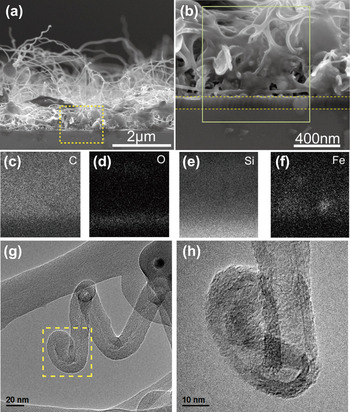
Figures 6(a) and 6(b) show the SEM images for the cross-section of carbon deposits synthesized by a 24 nm Fe film catalyst coated on SiO2 substrates. Consistent with the SEM images of Fig. 2, high yield MWCNCs are observed to be grown out from the surface of the catalyst film, as shown in Fig. 6(a). Figure 6(b) shows the enlarged SEM image of the catalyst film, where the thickness of the catalyst film is measured to be approximately 800 nm (much thicker than that of the Fe film before using it for synthesis of carbon deposits by the CVD process), from which many CNTs are protruded out. Figures 6(c)–6(f) show the EDX mappings of different element distributions in the area marked by a full line in Fig. 6(b), where the brightness is proportional to the relative contents of elements. C, O, Si, and Fe have been detected in this area, where C is originated from carbon deposits, O and Si are mainly originated from the Si substrate with a 100 nm SiO2 layer and Fe is originated from the catalyst film. A careful observation of Fig. 6(f) shows that the Fe element is mainly distributed at the bottom of the catalyst film, suggesting that MWCNCs and CNTs have a possible base growth mechanism. To further prove this point, TEM images of the MWCNC tip have been observed, as shown in Figs. 6(g) and 6(h). Indeed, no catalyst particle exists at the MWCNC closed tip, indicating that MWCNCs are grown via the base growth mechanism.
(a) and (b) cross-sectional SEM images of carbon deposits synthesized using 24-nm thick Fe films deposited on SiO2 substrates by ion sputtering. (c–f) EDX mapping of C, O, Si, and Fe for the square area shown in (b). (g) TEM and (h) enlarged TEM images of the MWCNC tip.

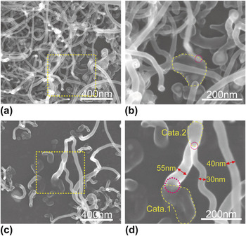
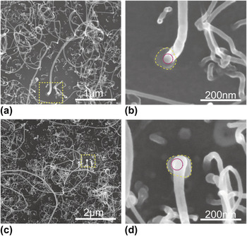
Figures 7(a) and 7(c) show the SEM images of two typical MWCNCs grown from 6-nm thick and 2-nm thick Fe film coated SiO2 substrates, respectively. It is found that the end of each coil is attached to the substrate with a root which is considered to act as a catalyst particle where the coil is grown. A similar phenomenon has also been observed for many other MWCNCs, as shown in Fig. S3. Therefore, the MWCNCs may have a base growth mechanism, consistent with the above deduction. Figures 7(b) and 7(d) show the respective enlarged SEM images for the roots of two coils in Figs. 7(a) and 7(c). It is noted that the size of the catalyst particle at the root of a coil is much larger than the filament diameter of the coil, which is similar as reported by Pan et al.Reference Kanada, Pan, Akita, Okazaki, Hirahara and Nakayama7 The catalyst particle has an irregular shape (indicated by dotted line circles). For example, the catalyst particle in Fig. 7(b) is narrowly triangular in shape having a size of around 140 nm; while the catalyst particle in Fig. 7(d) has sole like structure and has a size of around 170 nm along the long side and 100 nm along the short side. Another interesting aspect is that MWCNCs are only grown at the side of catalyst particles, as indicated by the small circles in Figs. 7(b) and 7(d) and Fig. S3. It is well known that the growth point for helical carbon nanomaterials is associated with a catalyst grain.Reference Kanada, Pan, Akita, Okazaki, Hirahara and Nakayama7,Reference Li and Pan42,Reference Qian, Pan, Li, Yu and Liu43 Therefore, the active point for the MWCNC growth is deduced to be located at the edge of a large catalyst particle.
(a) and (c) SEM images of two typical MWCNCs that are grown on 6-nm thick and 2-nm thick Fe film coated SiO2 substrates, respectively. (b) and (d) are the corresponding enlarged images of the roots of coils shown in (a) and (c).

Similarly, we have investigated the relationship between the size/shape of catalyst particles and the growth of CNTs, as shown in Fig. 8. Figures 8(a) and 8(c) show the SEM images of carbon deposits grown from 2-nm thick Fe film coated SiO2 substrates, where sparse CNTs with a variation in filament diameter can be observed. Figures 8(b) and 8(d) show the respective enlarged images of the roots of CNTs in Figs. 8(a) and 8(c). Similar to MWCNCs, the catalyst particles are observed at the roots of CNTs, indicating a base growth mechanism for CNTs. It is found that the diameter of catalyst particles at the root of a CNT is approximately 2 times larger than that of the produced CNT and the particle is an approximate circular shape (indicated by dotted line circles), differing from that of MWCNCs. Another difference between CNTs and MWCNCs is that CNTs are mainly grown from the center parts of catalyst particles (indicated by small circles) which indicate that the center part of catalyst particle is the real active point for the CNT growth.
(a) and (c) SEM images of two typical straight CNTs that are grown on 2-nm thick Fe film coated SiO2 substrates. (b) and (d) the corresponding enlarged images of the roots of CNTs shown in (a) and (c).

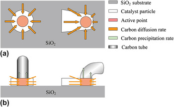
From the above discussions, we may conclude that the size, shape and composition of catalyst particles play an important role in determining the nature of carbon nanostructures produced. According to the present experimental observation and the images in Ref. Reference Kanada, Pan, Akita, Okazaki, Hirahara and Nakayama7, larger particles with irregular shapes would lead to the growth of helical MWCNCs, while particles with regular circular shapes may lead to the growth of straight CNTs. From this observation, the growth models for CNTs and MWCNCs have been proposed, as shown in Fig. 9. It is considered that each catalyst particle has an active point, from where carbon tubes can be grown out. For a symmetric (circular) catalyst particle, the active point is located at its center part; while for an irregular shaped catalyst particle, the active point tends to exist on one edge of the particle [Fig. 9(a)]. The hydrocarbon gas is supplied to the surfaces of catalyst particles and decomposed to carbon atoms that are diffused to active points from surroundings. The carbon diffusion rate varies at different parts of the irregular shaped catalyst particle, leading to an unequal extrusion of carbon atoms around the active point and finally growth of a helical CNC; while for the symmetric (circular) shaped catalyst particle, the carbon diffusion rate is the uniform along all parts of the catalyst, which leads to an equal extrusion of carbon atoms around the active point and finally growth of a straight CNT [Fig. 9(b)].
Illustration of the roles of catalyst shape in the growth of CNTs and MWCNCs: (a) top view, and (b) side view.

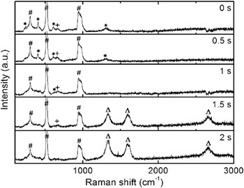
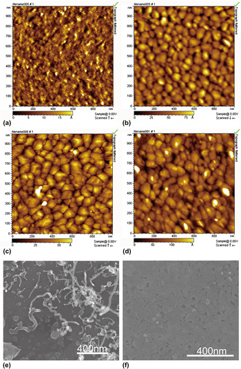
To understand the origin and evolution of large Fe catalyst particles, we have investigated the changes of Fe film coated on SiO2 substrates in the initial stage of CNT or CNC growth by introducing acetylene/Ar gases with flow rates of 1/260 sccm. Figure 10 shows the Raman spectra of a 6-nm thick Fe film after calcination in air at 700 °C for 30 min and a short time acetylene feeding. Three strong peaks (marked by #) observed in each Raman spectra are attributed to the SiO2 substrate. After calcination at 700 °C (0 s), many peaks marked by * and a small peak marked by + appear in the Raman spectra which correspond to Fe2O3 and Fe3O4, respectively. This result indicates that the Fe film has been oxidized after heating at 700 °C. The morphology of the Fe film before and after heating is compared using AFM, as shown in Figs. 11(a) and 11(b). The Fe film is flat before heating and begins to split after heating at 700 °C, forming irregular plate-like Fe–O particles. Figure 10 also shows the variation of Raman spectra for the Fe film after feeding acetylene for a short time. It is observed that the intensity of Fe2O3 peaks (marked by *) decreases when feeding acetylene for 0.5 s and almost disappears when feeding acetylene for 1 s, indicating that Fe2O3 particles have been deoxidized by acetylene within 1 s. AFM images show that compared with the Fe film after heating, there are no marked morphological changes for the Fe film during and after reduction, as shown in Figs. 11(c) and 11(d). The only difference is that the sizes of plate-like catalyst particles become larger and isolated particles are formed. Figure 11(e) shows the SEM image of a catalyst film after feeding acetylene for 1 s. Consistent with the AFM image of Fig. 11(e), large plate-like particles with a size of approximately 80 nm have been formed which are similar to those observed at the roots of CNTs or MWCNCs. When the acetylene feeding time was 1.5–2 s, three broad peaks (marked by Δ) appear in the Raman spectra which are due to the growth of carbon deposits. This is confirmed by the SEM observation of deposits on the substrate, as shown in Fig. 11(f). It is clear in the image that some CNTs together with MWCNCs have just been grown out from the catalyst particles, suggesting a rapid growth rate for CNTs and MWCNCs.
Raman spectra of a 6-nm thick Fe film (on SiO2 substrate) after calcination in air at 700 °C for 30 min and feeding acetylene/Ar gases with flow rates of 1/260 sccm for 0–2 s. The peaks marked by *, +, and Δ correspond to Fe2O3, Fe3O4, and carbon, respectively. The peaks marked by # are originated from the SiO2 substrate.

AFM images of a 6-nm-thick Fe film (on SiO2 substrate) (a) after evaporation, (b) after calcination in air at 700 °C for 30 min, (c) and (d) after feeding acetylene/Ar gases with flow rates of 1/260 sccm for 0.5 and 1 s. (e) and (f) SEM images of a 6-nm thick Fe film by feeding acetylene (1 sccm) for 1 and 1.5 s.

Since MWCNCs have been successfully synthesized by thermal CVD using Fe films as a catalyst, therefore, an Fe film prepared by ion sputtering is proved to be an effective catalyst for the MWCNC growth. However, the problem still exists that the yield of MWCNCs is not very high. A possible explanation for this result is that the shape and size of Fe catalyst particles have not been efficiently controlled. This is also a subject for our further study.
IV. CONCLUSIONS
Fe catalyst films prepared by ion sputtering have been applied for synthesizing MWCNCs. It is found that the film thickness and the choice of substrate play an important role in the growth of CNCs or MWCNCs. CNCs with large diameters and irregular CNTs can be obtained on Fe-film-coated ITO substrates by controlling the Fe film thickness, whereas MWCNCs together with straight CNTs are grown on Fe film coated SiO2 substrates. The large catalyst particles with different shapes of around 100 nm are observed at the roots of MWCNCs and CNTs, indicating a base growth mechanism. It is considered that each catalyst particle corresponds to an active point, from where carbon tubes can be grown out. For symmetric (circular) catalyst particles, the active point is located at the center part, from where the straight CNTs may be grown; while for irregular shaped catalyst particles, the active point tends to exist on the edge of the particle, from where the helical CNCs may be grown.
Supplementary Material
Supplementary materials can be viewed in this issue of the Journal of Materials Research by visiting http://journals.cambridge.org/jmr.
ACKNOWLEDGMENTS
This work was supported by the National Natural Science Foundation of China (Grant Nos. 51072027 and 11274055) and the Fundamental Research Funds for the Central Universities (Grant No. DUT12ZD204).