I. INTRODUCTION
The field of tissue engineering has gained much attention in the recent years, especially with the advent of novel technologies like 3D printing and bioprinting.Reference Vijayavenkataraman, Lu and Fuh1 Engineered tissues for regenerative medicine possesses many advantages over the grafting procedures (allografts or autografts).Reference Vijayavenkataraman, Lu and Fuh2 Ideally, patient’s own cells are used for fabrication of artificial tissue constructs. Hence, the problem of immunorejection with allografts or xenografts is overcome. Autografts, though less prone to immunorejection, suffer from other disadvantages such as donor site morbidity and might require a second surgery. With engineered tissue grafts, those post-operative complications are avoided. Porous scaffolds play an important role in the process of engineering an artificial tissue construct.Reference Hollister3 They act as a template for the attachment of cells, providing structural support for the cells, thereby guiding the formation of new tissue.Reference O’brien4 The design of scaffold structure and its properties (pore size, porosity, and mechanical properties) determine the fate of the cells cultured on these scaffolds. Greater the scaffold density, better are the mechanical properties and structural stability. But, the permeability of such denser scaffolds are less and hence, delivery of growth factor and nutrients will be affected. Greater the scaffold porosity, better are the permeability and mass transport properties. However, the scaffolds might not possess sufficient mechanical strength. Hence, a good scaffold design must consider both these properties and strike a right balance between them.Reference Hollister3 In addition, there are several other desirable properties of tissue engineering scaffolds including biocompatibility, biodegradability, and biomimicry. Different cell types prefer different scaffold propertiesReference Vijayavenkataraman, Shuo, Fuh and Lu5 and the scaffolds are designed per the intended application.
The native tissue environment is highly complex and heterogeneous in nature. Natural functional gradients across a spatial volume are present in the tissues to achieve the intended tissue functionality.Reference Leong, Chua, Sudarmadji and Yeong6 Most of the tissues have a layered or zonal architecture, such as skin or cartilage, and each layer or zone has its own distinct properties and cell types. The skin has three layers namely epidermis, dermis, and hypodermis, with each layer consisting of different cell types and functions and hence different architecture and properties.Reference Vijayavenkataraman, Lu and Fuh1 The epidermis contains keratinocytes and melanocytes, the dermis populated with fibroblasts, and the hypodermis predominantly contains adipose tissue. Articular cartilage has a zonal architecture, with three distinct zones namely superficial, middle, and deep zones.Reference Woodfield, Blitterswijk, Wijn, Sims, Hollander and Riesle7 Each zone has distinct and different cell types. The superficial zone has collagen fibers aligned parallel to the articulating surface with flattened chondrocytes, the middle zone has randomly aligned collagen fibers with rounded chondrocytes, and the deeper zone has collagen fibers aligned perpendicular to the articulating surface with large, spherical chondrocytes.Reference Sharma, Williams, Kim, Sun, Malik, Khan, Leong and Elisseeff8 To engineer such functionally graded tissues, the porous scaffolds used for cell seeding should also be functionally graded.Reference Bracaglia, Smith, Watson, Arumugasaamy, Mikos and Fisher9
Design and fabrication of functionally gradient scaffolds (FGS) have been previously reported in the literature but scarcely.Reference Miao and Sun10 Conventional scaffold fabrication methods such as solvent casting, gas foaming, freeze-drying, phase separation, and electrospinning have many limitations such as the use of toxic solvents and irregularly shaped pores.Reference Ma11,Reference Lu, Li and Chen12 Fabrication of FGS with these techniques is an onerous task if not impossible. Novel methods for fabrication of FGS such as sintering of graded particles,Reference Thieme, Wieters, Bergner, Scharnweber, Worch, Ndop, Kim and Grill13 vacuum infiltration,Reference Miao, Hu, Liu, Tio, Cheang, Khor, Ben-Nissan, Sher and Walsh14 freeze-casting,Reference Macchetta, Turner and Bowen15 and pulsed electric current sinteringReference Suk, Choi, Kim, Do Kim and Kwon16 have been reported. However, there are several limitations of these processes including limited porosity range, poor pore interconnectivity, and less controllability of pore size and porosity. The common limitation of all these methods is that the pore size, fiber dimensions, and direction cannot be controlled precisely. Additive manufacturing, commonly referred to as 3D printing, circumvents this limitation. With 3D printing, the pore size, porosity, fiber diameter, and alignment can be precisely controlled. 3D porous scaffolds with any complex geometry can be fabricated with high accuracy, precision, and repeatability. Additive manufacturing is an umbrella term for several different processes, which involves fabricating a 3D object in a layer-by-layer (additive) fashion. These processes are grouped into seven major categories by ASTM namely VAT photopolymerization, material jetting, binder jetting, material extrusion, powder bed fusion, sheet lamination, and directed energy deposition. There are more than 40 different additive manufacturing processes reported or being developed that belongs to one of these seven categories.Reference An, Teoh, Suntornnond and Chua17 However, in the field of tissue engineering scaffolds, only powder bed fusion [i.e., SLS and Stereolithography (SLA)], and material extrusion (commonly referred to as FDM) processes were used for fabrication of tissue engineering scaffolds.Reference Do, Khorsand, Geary and Salem18 Though SLS is predominantly used to fabricate metals, biomaterials such as hydroxyapatite (HA) had been processed into 3D scaffolds using SLS.Reference Liu19 Nevertheless, there are several drawbacks associated with SLS that prevents this technology from commonly being used for scaffold fabrication. The requirement of materials that can withstand the laser heat and high temperatures (up to 1400 °C), shrinkage of the scaffold during the sintering process, and extensive pre-and post-processing treatments of the powdered material are some of its limitations.Reference Do, Khorsand, Geary and Salem18 SLA is a high resolution (nm range) process that can be used to fabricate 3D scaffolds of very high precision. However, only photopolymers such as polypropylene fumarate and polyethylene glycol acrylate can be processed using this technique, in the presence of photoinitiators such as Irgacure. In addition to the limited range of materials that can be processed, the photoinitiators used for the photopolymerization process are toxic to the cells.Reference Sabnis, Rahimi, Chapman and Nguyen20,Reference Vijayavenkataraman21 The drawbacks of SLS and SLA make material extrusion the most widely used 3D printing method for fabrication of tissue engineering scaffolds. Several biomaterials such as polycaprolactone (PCL),Reference Hutmacher, Schantz, Zein, Ng, Teoh and Tan22 poly(lactide-co-glycolic)/poly(L-lactide) (PLGA/PLLA),Reference Park, Wu and Griffith23 polylactic acid,Reference Serra, Ortiz-Hernandez, Engel, Planell and Navarro24 PCL–tri-calcium phosphate (TCP),Reference Khojasteh, Behnia, Hosseini, Dehghan, Abbasnia and Abbas25 and PCL/HA.Reference Xu, Ye, Wei, Zhong, Chen, Xu and He26 Though the pore size, porosity, and fiber diameter can be precisely controlled by FDM, the resolution offered by the process is low (∼0.1 mm).Reference An, Teoh, Suntornnond and Chua17
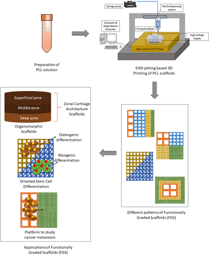
Electrohydrodynamic jetting (EHD jetting) is a technology that can be used to fabricate scaffolds with high precision, accuracy, and resolution.Reference Liu, Vijayavenkataraman, Wang, Jing, Sun and He27–Reference Wang, Vijayavenkataraman, Wu, Shu, Sun and Hsi29 It is also a layer-by-layer process and utilizes a high voltage applied between the nozzle and substrate to extrude very thin aligned fibers (down to 5 μm). The working principle of EHD jetting is similar to that of electrospinning and described in detail in our previous studies.Reference Liu, Vijayavenkataraman, Wang, Jing, Sun and He27,Reference Wang, Vijayavenkataraman, Wu, Shu, Sun and Hsi29 Briefly, the high voltage difference between the nozzle and the substrate creates a strong electric field force and when this electric field force overcomes the surface tension and the viscoelastic force of the solution in the nozzle, fibers are drawn out of the nozzle. However, in the electrospinning process, the fibers formed are quite randomized and the fiber orientation could not be controlled precisely. EHD jetting is a near-field electrohydrodynamic process, where the fiber orientation can be controlled precisely using computer control. The main difference between the two processes, in terms of the process parameters, is the range of voltage applied and the distance between the nozzle and the substrate. While the voltage applied in electrospinning is usually higher than 10 kV, only 2–3 kV is used in the EHD jetting process. Similarly, the nozzle to substrate distance is much higher in electrospinning (>5 cm) than the EHD jetting (<4 mm). Precise orientation and control of fibers are important in the field of tissue engineering because the native tissues such as tendon, cartilage, ligament, and muscle; and the collagen fibers are arranged in a particular arrangement with a unique orientation which determines the anisotropic mechanical properties of these tissues. Therefore, EHD jetting is a more suitable process for fabrication of biomimetic tissue scaffolds than electrospinning. In this paper, FGS of different patterns has been fabricated using EHD jetting to show the versatility of the process. An overview of the whole process is pictorially depicted in Fig. 1. FGS scaffolds with pore size gradient in the radial (R1, R2, and R3), sectional (S), diagonal (D1 and D2), concentric square (C), and axial (A) directions were designed. Computation studies were performed on all these different FGS. The fabricated FGS patterns were tested for their mechanical properties under tensile loading and the experimental results were compared with the simulation results.
Overview of the EHD-jet 3D printing process and applications of FGS.

II. MATERIALS AND METHODS
A. Materials
PCL pellets with an average molecular weight of 80 kDa (PCL, Sigma-Aldrich Pte Ltd., Singapore) was used as the solute biomaterial. Glacial acetic acid (>99.7% pure, Sigma-Aldrich Pte Ltd., Singapore) was used as the solvent.
B. Preparation of PCL solution
A concentration of 70% (w/v) is used in all the experiments. PCL pellets suspended in acetic acid was ultra-sonicated at 60 °C and 40 kHz for 3 h. It was stirred well every one hour to obtain a homogeneous solution. The solution was left to cool down to the room temperature before loading it into the syringe for EHD jetting.
C. Fabrication of 3D scaffolds using EHD jetting
An in-house built 3D printing-assisted EHD jetting system was used for the fabrication of scaffolds. The main components of the system are the high voltage power source, a high precision XYZT stage along with the controller, a syringe pump, and a computer. Software for stage control, connecting tubes, syringes, and needles are other components. A 13 mm internal diameter syringe and 0.5 mm internal diameter needle were used in all the experimental trials. A high voltage of 2.4 kV is applied between the nozzle and the substrate, the distance between the nozzle and substrate is 2 mm, the flow rate of the solution is 10 µL/min, and a stage speed of 75–100 mm/s. Polished silicon wafers of diameter 100 mm were used as substrates. All the scaffolds printed and tested consisted of 20 layers.
D. Materials characterization
1. Scanning electron microscopy
The EHD jetted scaffolds were sputter-coated with gold (JEOL JFC-1200 Fine Coater, Tokyo, Japan) to render it conductive and visualized using a scanning electron microscope (JEOL JSM-5500, Tokyo, Japan). The average fiber diameter and pore size were calculated from the SEM images using image analysis software (ImageJ, National Institute of Health, Bethesda, Maryland).
2. Raman spectroscopy
Raman spectra were recorded on a Horiba Jobin Yvon Modular Raman spectrometer at a laser excitation wave length of 514 nm (Stellar Pro Argon-ion laser Modu-Laser LLC., Centerville, Utah) for the as-received PCL pellets and EHD-jetted scaffolds.
E. Mechanical testing
Tensile properties of the scaffolds were determined with a table-top micro-tester (Instron 3345, Norwood, Massachusetts) using a load cell of 100 N capacities. Test specimens are rectangular scaffolds with a length and width of 30 mm (dimensions are kept constant for all the different patterns) and were tested at a strain rate of 10 mm/min at ambient conditions. An offset strain of 0.2% was used to determine the yield stress, yield strain, and tensile modulus from the stress–strain curves.
F. Computational studies
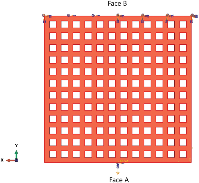
All modeling and simulations were performed in ABAQUS (Dassault Systèmes SOLIDWORKS Corp., Waltham, Massachusetts), using the C3D10 meshing element with a mesh size of 40 μm. Material properties of PCL [elastic modulus (E o) of 400 MPa and a Poisson’s ratio of 0.33] were used for the computational studies.Reference Vijayavenkataraman, Shuo, Fuh and Lu5 For the numerical computation of the elastic modulus, a uniform fixed displacement in a single direction was applied (the Y direction) on Face A of the scaffold (shown in Fig. 2). The opposite face (Face B) of the scaffold was constrained. The average reaction force produced on Face A was used to determine the elastic modulus of the scaffold using the equation given below.
 $$E = {\sigma \over \varepsilon } = {{{F \over A}} \over {{{\Delta L} \over {{L_{\rm{o}}}}}}}\quad ,$$
where F—reaction force obtained from FEM studies; A—cross-sectional area; ΔL—displacement; and L o—original length.
Representative image of the loads and constraints for the numerical analysis of scaffolds under a tensile loading. Face B was constrained, and a uniform displacement in a single direction was imposed on Face A.

G. Statistical analysis
Experiments were run in triplicates and all measurements were expressed as mean ± SD. One-way ANOVA test was used to determine any significant differences existed between the mean values of the experimental groups. Differences were considered statistically significant at p < 0.05.
III. RESULTS
A. Design of FGS scaffolds with different patterns
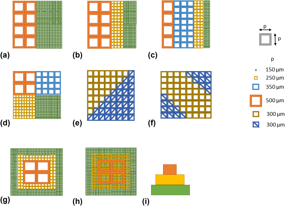
Design of FGS scaffolds with pore size/porosity graded in the radial (R1, R2, and R3), sectional (S), diagonal (D1 and D2), concentric square (C), and axial (A) directions were conceived as shown in Fig. 3. Square pores (side length ‘p’) were used for all the patterns except diagonal FGS, where triangular pores were also used along with square pores. Pore size is denoted by the side length ‘p’ of the square pore. Five different pore sizes were used in this study, which includes 150, 250, 300, 350, and 500 μm. In the radial FGS, three different patterns namely R1, R2, and R3 with two, three, and four different pore size/porosity regions, respectively, were designed. R1 has two regions with different pore sizes of 150 and 500 μm, R2 has three regions with different pore sizes of 150, 250, and 500 μm, and R3 has four regions with different pore sizes of 150, 250, 350, and 500 μm. A sectional FGS (S) with four different pore size/porosity regions (150, 250, 350, and 500 μm) was designed. Two diagonal FGS D1 and D2 were designed, with D1 having two different pore size/porosity regions (300 and 300 μm divided diagonally) and D2 having three different pore size/porosity regions (300 μm divided diagonally at the bottom left and top right with 300 μm in between). The concentric FGS (C) has three different pore size/porosity regions, with 500 μm at the inner square, 250 μm in the middle, and 150 μm at the outer square. In the axial FGS, three different pore size/porosity regions, 150, 250, and 500 μm are stacked, respectively, from the bottom. In addition, scaffolds with a single pore size (each of the six namely 150, 250, 300, 350, 500, and 300 μm divided diagonally) were used as a control. These different FGS patterns were designed to prove the versatility of the EHD-jet 3D printing to fabricate FGS.
Design of FGS scaffolds with pore size/porosity graded in the (a–c) radial (R1, R2, and R3, respectively), (d) sectional (S), (e and f) diagonal (D1 and D2, respectively), (g) concentric square (C), and (h and i) axial (A) directions (top view and side view, respectively).

B. Computational studies
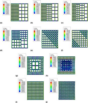
All the eight different patterns (R1, R2, R3, S, D1, D2, C, and A) shown in Fig. 3 were modeled using ABAQUS and mechanical testing simulation under tensile loading was performed. Tensile test simulation for scaffolds with a single pore size (each of the six namely 150, 250, 300, 350, 500, and 300 μm divided diagonally) that are used as a control was also performed. Simulation results for radial FGS (R1, R2, and R3) are shown in Fig. 4. Stress distribution in patterns R1, R2, and R3 are shown in (a), (b), and (c), respectively. In all the three patterns, the stress distribution across the different pore size regions are similar without much variation. Nonetheless, the high-stress points are denser in the smaller pore size regions than the larger pore size region.
Simulation results (stress distribution) for different FGS (a–c) radial FGS R1, R2, and R3, respectively, (d) sectional FGS S, (e and f) diagonal FGS D1, and D2, respectively, (g) concentric FGS C, (h) axial FGS A, and (i and j) simulation results for single porosity scaffolds (control), scaffold with pore size 150 and 300 μm with diagonal division, respectively.

Simulation results for sectional FGS (S) are shown in Fig. 4(d). Stress distribution shown in Fig. 4(d) reveals that the larger pore size region (350 and 500 μm) experiences higher stress than the smaller pore size region (150 and 250 μm). Stress distribution for diagonal FGS in patterns D1 and D2 are shown in Figs. 4(e) and 4(f), respectively. In the diagonal FGS, the stress level experienced by the longitudinal and diagonal fibers is much higher than the stress experienced by the transverse fibers. Also, the high-stress points are denser at the interface of all the three fibers (longitudinal, transverse, and diagonal) than at the interface of longitudinal and transverse fibers.
Stress distribution for concentric FGS (C) shown in Fig. 4(g) reveals that the longitudinal fibers present in the inner (500 μm) and the middle square (250 μm) experience higher stress than the smaller pore size region (150 μm). But, the stress concentration at the fiber interface is much higher in the smaller pore size region (150 μm), especially at the point of transition between the pore size regions of 250–150 μm. Stress distribution for axial FGS (A) shown in Fig. 4(h) reveals that the bottom layer containing the smaller pore size (150 μm) experience the highest stress than the upper layers (250 and 500 μm). High-stress concentration can be seen on the longitudinal fibers at the two ends of the scaffold. The strain distribution also proves that the central part of the scaffold has the maximum displacement.
Simulation results for single porosity control scaffolds are shown in Figs. 4(i) and 4(j). Stress distribution for a single pore size scaffold (150 μm) is shown in Fig. 4(i) as a representative result for all the other single pore size control scaffolds (250, 300, 350, and 500 μm) as they are similar, except the 300 μm divided diagonally, which is shown in Fig. 4(j). It can be seen that the stress experienced by the longitudinal fibers, along which direction the stress is applied, experiences much higher stress compared to the transverse fibers. This is a common observation across the different FGS patterns. With the single porosity scaffold consisting of 300 μm pores with diagonal fibers [Fig. 4(j)], the stress experienced by the longitudinal and diagonal fibers is higher than that of the transverse fibers.
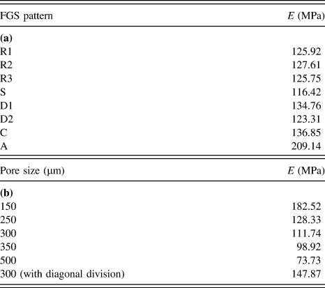
The tensile modulus (E) computed from the computational studies for different FGS patterns and for single porosity control scaffolds is shown in Table I, (a) and (b), respectively. It can be seen from Table I (b) that the tensile modulus is inversely proportional to the pore size. Comparing (a) and (b), it can be seen that the tensile modulus of an FGS lies in between the range of values of the individual single porosity control scaffolds that forms FGS. For example, with pattern R1, the tensile modulus of R1 (125.92 MPa) lies between the tensile modulus values of single porosity scaffolds with a pore size of 500 μm (73.73 MPa) and 150 μm (182.52 MPa).
Tensile modulus (E) computed from the computational studies (a) for different FGS patterns, and (b) for single porosity control scaffolds.

C. Fabrication of FGS using EHD-jetting-based 3D printing
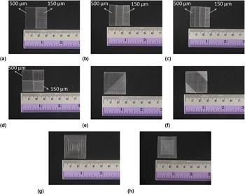
EHD-jetting-based 3D printing was used to fabricate FGS of all the patterns designed. The working principle of EHD jetting is based on the balance between the electrostatic force and the combined surface tension and viscoelastic force of the liquid. A high voltage (DC) is applied between the nozzle and the substrate, the surface tension force of the liquid at the nozzle tip is overcome by the electrostatic force between the nozzle and substrate, forcing the solution to come out of the nozzle and printed on to the substrate. The parameters used for printing the scaffolds are mentioned in Sec. II.C. The images of EHD-jetted FGS are shown in Fig. 5. The different pore size regions in each FGS are clearly differentiable as can be seen from Fig. 5.
Images of FGS scaffolds fabricated using EHD-jetting-based 3D printing with pore size/porosity graded in the (a–c) radial FGS R1, R2, and R3, respectively, (d) sectional FGS S, (e and f) diagonal FGS D1, and D2, respectively, (g) concentric FGS C, and (h) axial FGS A.

D. Materials characterization
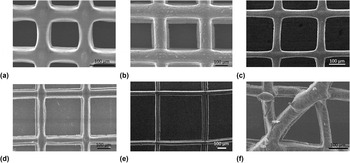
The SEM images of control scaffolds with five different pore sizes (150 ± 15, 250 ± 15, 300 ± 15, 350 ± 15, and 500 ± 15 μm) are shown in Figs. 6(a)–6(f). The average fiber diameter from the measurements is 47 ± 5 um. The fibers are uniformly aligned with a defined pore shape unlike the porous scaffolds obtained by traditional scaffold fabrication techniques such as solvent casting, gas foaming, freeze-drying, and randomly aligned electrospun fibers/scaffolds.
SEM images of scaffolds with different pore sizes fabricated using EHD-jetting-based 3D printing. (a) 150 ± 15 μm, (b) 250 ± 15 μm, (c) 300 ± 15 μm, (d) 350 ± 15 μm, (e) 500 ± 15 μm, and (f) 300 ± 15 μm with the diagonal division.

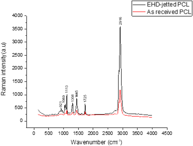
The Raman spectrum of the as-received PCL pellets and PCL scaffolds fabricated using EHD-jetting-based 3D printing is shown in Fig. 7. The characteristic peaks of PCL, namely C=O peak at 1725 cm−1, CH2 asymmetric stretching at 2916 cm−1, C–COC crystalline at 1113 cm−1, and C–COO crystalline at 921 cm−1 are present in both as-received PCL pellets and EHD-jetted scaffolds.
Raman spectra of the as-received PCL pellets and EHD-jetted PCL scaffolds excited with a 514 nm laser line, showing the characteristic peaks of PCL.

E. Mechanical testing
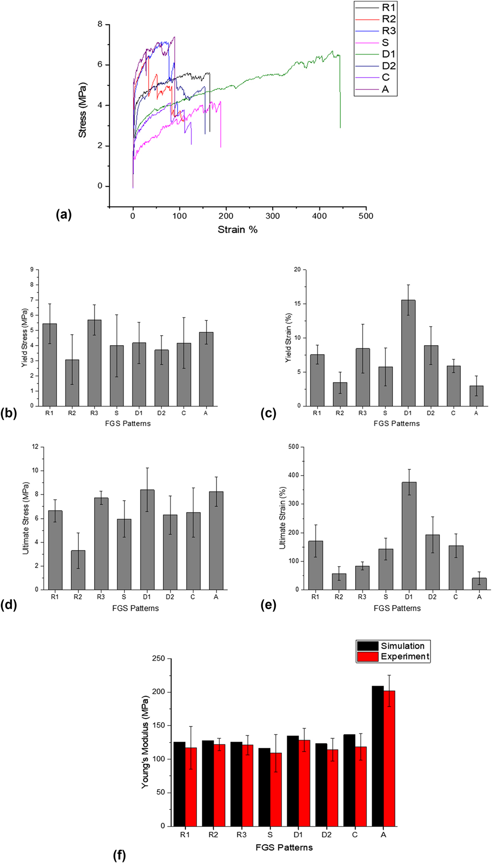
Stress–strain curves of different patterns of FGS are shown in Fig. 8(a). The yield stress, yield strain, ultimate stress, and ultimate strain are also shown in Figs. 8(b)–8(e). The tensile modulus from the computational study and experiments are shown in Fig. 8(f).
Mechanical properties of FGS: (a) representative stress–strain curves, (b) yield stress, (c) yield strain, (d) ultimate stress, (e) ultimate strain, and (f) tensile modulus from the simulation and experiment.

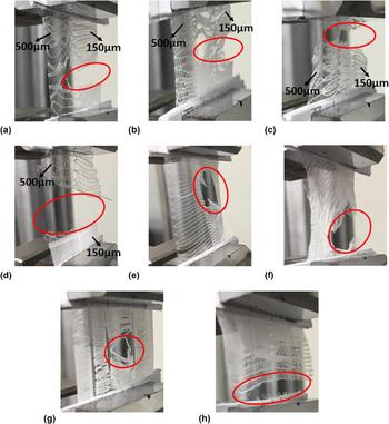
The tensile test experimental images of the FGS patterns after failure are shown in Fig. 9. The region of failure is circled in red.
Images of tensile test of FGS scaffolds at failure with pore size/porosity graded in the (a–c) radial FGS R1, R2, and R3, respectively, (d) sectional FGS S, (e and f) diagonal FGS D1, and D2, respectively, (g) concentric FGS C, and (h) axial FGS A.

From the stress–strain curves of different FGS shown in Fig. 8(a), it can be seen that all the curves follow a typical stress–strain curve pattern of polymers. With the radial FGS, different pore size regions fail in a sequence and it can be seen as drastic fall steps in the stress–strain curve. For instance, in R2, where there are three different pore size regions, namely 500, 250, and 150 μm, the region with pore size 150 μm fails first, which is indicated by a steep fall in the stress at a strain of around 33%, followed by the region with pore size 250 μm showing another steep fall in stress at a strain of around 51%, and finally the region with pore size 500 μm showing a steep fall in stress at a strain of around 83% before final failure at around 108% strain. Also, it can be seen that the ultimate strain of the diagonal FGS D1 is far greater than all the other FGS patterns.
The yield stress, yield strain, ultimate stress, and ultimate strain of different FGS are shown in Figs. 8(b)–8(e). The mean yield stress of all the FGS lies between 3 and 6 MPa as can be seen in Fig. 8(b) and the mean yield strain between 3 and 9% as can be seen in Fig. 8(c), except the diagonal FGS D1, which shows a yield strain of 15.56%. The mean ultimate stress of all the FGS lies between 3.5 and 8.4 MPa as can be seen in Fig. 8(d) and the mean ultimate strain between 40 and 200% as can be seen in Fig. 8(e), except the diagonal FGS D1, which has an ultimate strain of 376.83%. The tensile modulus from computational study and experiments is shown in Fig. 8(f). It can be seen that the experimental tensile modulus values are lesser than those obtained from the simulation in all the cases.
From the tensile test experimental images of the radial FGS patterns (R1, R2, and R3) after failure shown in Fig. 9, the region with the smaller pore size (150 μm) fails first in all the three radial FGS. In the sectional FGS (S), the scaffold fails at the intersection of regions of larger pore size (350 and 500 μm) and smaller pore size (150 and 250 μm). In the diagonal FGS (D1 and D2) patterns, the point of failure is always on the intersection points of diagonal and linear fibers in the diagonal side. Also, the strain is higher in the longitudinal and diagonal fibers than on the transverse fibers as can be seen in the figure. With concentric FGS (C), the failure happens from inside out, starting from the region of larger pore size (500 μm) to smaller pore size (150 μm). In the axial FGS (A), the failure takes place in the smaller pore size region (150 μm), which is the bottom layer and the failure happens at the extreme end of the scaffold.
IV. DISCUSSION
Porous polymeric scaffolds play an important role in tissue engineering. The native tissue environment is highly complex and heterogeneous in nature. Hence, organomorphic scaffolds with functional gradients are necessary to give the cells their natural tissue microenvironment and thus aiding the fabrication of the biomimetic engineered tissue construct for regenerative medicine and other applications. In this study, we fabricated various patterns of FGS using the EHD-jetting-based 3D printing method. Our results demonstrate that EHD jetting technology is capable of fabricating FGS with precise control of the scaffold morphology including the fiber diameter, pore size, porosity, and fiber alignment. Eight different patterns of FGS, with pore size graded in the radial (R1, R2, and R3), sectional (S), diagonal (D1 and D2), concentric square (C), and axial (A) directions were designed, simulated and printed successfully.
FGS with pore size graded in the radial (R1, R2, and R3), sectional (S), diagonal (D1 and D2), concentric square (C), and axial (A) directions were designed as shown in Fig. 3 and fabricated using EHD-jetting-based 3D printing as shown in Fig. 5. From the SEM images of the different pore sizes used in this study (Fig. 6), the ability of EHD jetting to control the pore size is proven. Raman spectrum of the as-received PCL pellet and EHD-jetted PCL scaffold (Fig. 7) proves that there is no change in the material property induced by the fabrication process. The stress–strain curves of all the FGS patterns [Fig. 8(a)] follow the typical stress–strain curve pattern of polymers. The yield stress, yield strain, ultimate stress, and ultimate strain of different FGS are shown in Figs. 8(b)–8(e). It can be seen that the diagonal FGS D1 possesses the greatest yield strain and ultimate strain among all the FGS patterns. The presence of long diagonal fibers in D1 aids in having such a large strain. Hence, an FGS with regions of same yield and ultimate stress but with higher yield strain and ultimate strain could be fabricated by varying the fiber alignment. At the same time, it has to be noted that D2 which also has diagonal fibers had neither a higher yield strain nor higher ultimate strain. It can be inferred that not only the fiber alignment but also the spatial arrangement of the fibers or pore size regions also determine the mechanical properties of the FGS. From Fig. 8(f), it can be seen that the experimental tensile modulus values are lesser than those obtained from the simulation in all the cases. It is due to the morphological differences between the design and fabricated scaffolds.Reference Uth, Mueller, Smucker and Yousefi30
Computational studies of FGS in the tensile loading were also performed and the stress and strain distribution of various FGS are shown in Figs. 4(a)–4(g). The tensile test experimental images of the FGS patterns after failure are shown in Fig. 9. Inferences from the simulation substantiate the experimental results. The region with the smaller pore size (150 μm) fails first in all the three radial FGS (R1, R2, and R3) as shown in Fig. 9. Though we expect the region with larger pore size (500 μm) to fail first as it is weaker, it can be seen from the stress distribution in radial FGS shown in Figs. 4(a)–4(c) that the high-stress points are denser in the smaller pore size regions than the larger pore size region, which explains the experimental observation. In the sectional FGS (S), the scaffold fails at the intersection of regions of larger pore size (350 and 500 μm) and smaller pore size (150 and 250 μm) and the failure happens in the larger pore size (350 and 500 μm) region. Stress distribution in S [shown in Fig. 4(d)] goes in line with the experimental observation as the larger pore size region experiencing higher stress than the smaller pore size region. It is worth noting that while the smaller pore size region fails first in radial FGS and the larger pore size region fails first in sectional FGS. Hence, it could be inferred that spatial distribution of different pore size regions has an influence on the mechanical behavior of the scaffolds and this could be used to tune the region-specific and macro-level mechanical properties of the FGS. In the diagonal FGS (D1 and D2) patterns, the point of failure is always on the intersection points of diagonal and linear fibers in the diagonal side, as can be seen in Fig. 9. It can be seen from the simulation results of D1 and D2 shown in Figs. 4(e) and 4(f) that the high-stress points are denser at the intersection of all the three fibers (longitudinal, transverse, and diagonal), which explains the experimental observation. With concentric FGS (C), the failure happens from inside out, starting from the region of larger pore size (500 μm) to smaller pore size (150 μm) as shown in Fig. 9, which is explained by the stress distribution pattern of C [Fig. 4(g)] where the inner and middle regions experience higher stress than the outer smaller pore size region. It should be noted that though the stress concentration at the fiber interface is much higher in the smaller pore size region at the point of transition between the pore size regions of 250–150 μm, the failure first happens in the inner larger pore size region as the overall stress is much higher in the inner region compared to the outer region. Comparing the simulation and experimental results of radial and concentric FGS, it can be concluded that when there is a uniform stress distribution across the different regions of the scaffold, the scaffold fails at the region containing denser stress concentration points and when there is a nonuniform stress distribution across the different regions of the scaffold, the scaffold fails at the region containing higher stress distribution and not in the region containing denser stress concentration points. In the axial FGS (A), the failure takes place in the smaller pore size region (150 μm) at the extreme end of the scaffold, just as predicted by the stress distribution contour shown in Fig. 4(h). The computational study and the experimental observation agree with each other in all the cases.
This study demonstrates the feasibility of fabricating FGS using EHD-jetting-based 3D printing technology. The applications of such FGS are many, a few of which are depicted in Fig. 1. Many biological tissues such as cartilage and skin have a zonal or layered architecture, with each zone or layer having a specific pore structure, pore size, fiber alignment, and mechanical properties. Organomorphic scaffolds having the same graded structure as the native tissue can be fabricated using this method. Another potential application of FGS is interfacial tissue engineering, with the interface between two different tissues, have a gradient structure. An FGS with different regions having different mechanical stiffness can be fabricated such that the stem cells cultured on the FGS would differentiate into different lineages (neurogenic, adipogenic, myogenic, or osteogenic) and could potentially be used for multiculture systems. FGS could also be used to construct an in vitro cancer metastasis model, where two regions with properties mimicking two tissues can be fabricated and the migration and mechanisms of cancer cells from one region to another could be studied.
V. CONCLUSION
EHD-jetting-based 3D printing is used in this study to fabricate scaffolds with a pore size gradient. Different patterns of gradients along radial, sectional, diagonal, concentric, and axial directions were designed and fabricated. Mechanical testing of the scaffolds and computational studies were also performed. The computational study and the experimental observation agree with each other in all the cases. The spatial distribution of different pore size regions has an effect on the mechanical behavior of the scaffold. While failure happens first in the smaller pore size region in a radial FGS, larger pore size regions fail first in a sectional FGS. Hence, an appropriate distribution of pore size regions is required to achieve desired mechanical behavior of the scaffolds. Computational studies can be used to optimize the distribution of pore size regions. Among all the FGS patterns, the diagonal FGS (D1) possesses the greatest yield strain and ultimate strain, while the yield stress and ultimate stress values are within the same range as other FGS patterns. Hence, an FGS with regions of same yield and ultimate stress but with higher yield strain and ultimate strain could be fabricated by varying the fiber alignment. In a FGS with a uniform stress distribution across the different regions of the scaffold, the scaffold fails at the region containing denser stress concentration points, whereas in an FGS with nonuniform stress distribution across the different regions of the scaffold, the scaffold fails at the region containing higher stress distribution and not in the region containing denser stress concentration points. Such graded polymeric scaffolds have many potential applications including fabrication of organomorphic scaffolds, multiculture systems, interfacial tissue engineering, and in vitro cancer metastasis models.