Introduction
Wireless body area network (WBAN) has been developing rapidly in the communication field [Reference Haga, Saito, Takahashi and Ito1, Reference Halland and Hao2]. It has attracted attention of scientists and researchers because of its wide range of applications in military, sports, medical monitoring, and several other fields [Reference Zu, Wu and Zhang3, Reference Arif, Zubair, Ali, Khan and Mehmood4]. Wearable antennas used in WBAN have particular criteria in terms of design and size as compared to conventional antennas, such as waist, neck, and arm-wearable antennas must be in the form of a belt or button [Reference Pei, Leach, Lim, Wang, Wang, Wang, Jiang and Huang5–Reference Foroozesh and Shafai9]. As a result, enhancing the performance of wearable antennas is critical, particularly in the realm of telemedicine systems [Reference Pei, Leach, Lim, Wang, Wang, Wang, Jiang and Huang5].
Monopole antennas are commonly utilized in the field of WBAN and are placed near to the human body, which results an impedance mismatching and a significant reduction in antenna radiation performance [Reference Zhu and Langley10–Reference Ashyap, Dahlan, Zainal Abidin, Abbasi, Kamarudin, Majid, Dahri, Jamaluddin and Alomainy14]. The electromagnetic band gap (EBG) and artificial magnetic conductor (AMC) based antennas proved to be great help in reducing the coupling effect of human body on the designed antennas [Reference Zhu and Langley10, Reference Mantash, Tarot, Collardey and Mahdjoubi15, Reference Yan, Soh and Vandenbosch16]. Additionally, flexible AMC-based wearable antennas can help in reducing SAR value of the designed structure, which makes it simpler for researchers to develop antennas in accordance with human safety requirements [Reference Gao, Zhang, Geng, Meng and Hu17–Reference Kim, Ren, Lee, Rida, Nikolaou and Tentzeris19]. In previous years, the design of AMC-based metasurface structures has focused on minimizing back lobe radiation, improving impedance bandwidth, enhancing antenna performance, and increasing gain. AMC-based metasurfaces also have the characteristics of a reflecting plane wave in the same phase and can achieve the performance of an ideal magnetic conductor in a definite frequency band [Reference Agarwal, Guo and Salam20–Reference Catarinucci, Chietera and Colella22]. Recently, an AMC-based low-profile wearable antenna for the ISM band with dimensions of 102 × 68 mm2 and a peak gain of 6.12 dBi is presented [Reference Alemaryeen and Noghanian23]. A wearable monopole antenna consisting of tri-annular square ring with AMC is proposed for ISM, WBAN, and WiMAX applications. The proposed design works in the ISM [Reference Lai, Wang, Sun, Zhao and Zeng24]. A triple transmission line is used to improve the gain of wearable antenna operation in the dual band region of 1.7–2.5 and 5.4–5.95 GHz with gain value of 9.86 dBi with larger antenna dimension of 0.57λ × 0.67λ [Reference Khajeh-Khalili, Shahriari and Haghshenas25]. Then, a two-element textile-based MIMO antenna is proposed with high isolation and polarization diversity. The proposed circularly polarized antenna operates in the region of 3.3–4.3 GHz [Reference Kumar, De and Jain26]. A circularly polarized UWB antenna is designed consisting of a metasurface structure with dual-band notch characteristics [Reference Lin, Liu, Wang, Zheng, Wang and Li27]. In [Reference Liu, Zhang, Li, Cui, Liang, Wang, Fan, Zheng and Li28] a miniaturized implantable antenna is proposed for ISM band applications. The proposed antenna exhibits impedance and axial ratio bandwidth (ARBW) of 2.25–2.78 and 2.32–2.63 GHz, respectively.
But the size of antenna is quite large. Thus, in the field of WBAN, wearable antenna plays an important role for wireless communication, and the performance of wearable antennas should not be degraded due to bending or crumpling. Hence it is necessary to design a miniaturized, low-cost wearable antenna with good radiation performance.
In this work, we have proposed and experimentally verified a low-profile CRLH-TL-based CP antenna combined with a miniaturized AMC structure for ISM band wearable applications. The paper is organized as follows: in section “Proposed antenna configuration and analysis” CRLH-TL-based antenna is designed and its equivalent circuit diagram is discussed. AMC unit cell structure is also designed and discussed in section “Proposed antenna configuration and analysis”. Section “Proposed design integration of CRLH-based antenna and AMC” is based on the design and analysis of AMC integrated antenna. Section “Evaluation of AMC antenna performance under bending conditions” is dedicated to the discussion on the performance of AMC antenna for different bending conditions to evaluate the performance of antenna for wearable applications. Discussion on experimental results is done in section “Experimental results and discussion”, and finally, conclusions are drawn in section “Performance of the proposed antenna on the human body”.
Proposed antenna configuration and analysis
Antenna design
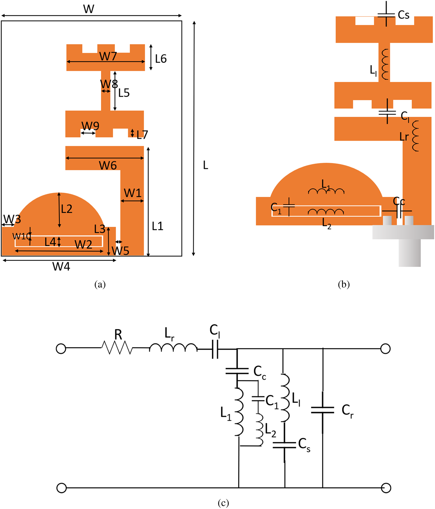
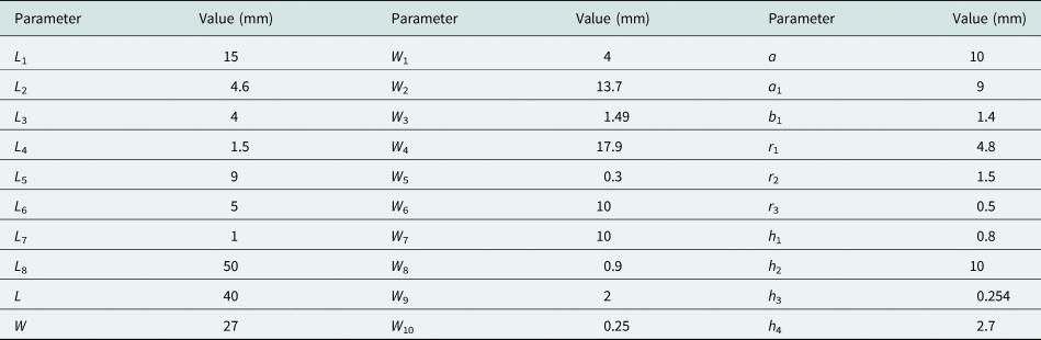
The schematic diagram of the CP antenna is shown in Fig. 1(a). The designed CPW fed CRLH-TL-based CP antenna is fabricated on Rogers RT duriod 5880 and it employs an asymmetric co-planar waveguide feeding strip scheme. The CRLH-based TL unit cell is realized on an L-shaped rectangular strip that serves as the antenna's feedline. The proposed antenna uses an asymmetric ground plane consisting of a rectangular-shaped slot. The equivalent circuit of the proposed structure based on CRLH-TL is shown in Figs 1(b) and 1(c). The L-shaped feed of the antenna gives the series inductance (Lr) of the CRLH-TL, as shown in Fig. 1(b), while a small rectangular ring slot will offer capacitance in series (Cl), forming the series arm (Lr and Cl) of the CRLH inspired TL. Further, rectangular strip attached to the feed line provides shunt inductance (Ll). The virtual ground for the shunt inductor is provided by the rectangular stub, which substitutes conventional CRLH-TL-based design concept of using shorted vias or metal posts for ground [Reference Ameen and Chaudhary29, Reference Ameen and Chaudhary30]. The coupling capacitor Cc is formed by the gap w 5 between feed line and asymmetric ground plane. Further, coupling between the CRLH-TL and the ground plane supplies the shunt capacitor (Cr) that makes up the CRLH-TL shunt arm (Ll, Cs, Cc, and Cr). A rectangular annular ring slot with gap w 10 is loaded in the ground plane to keep the antenna compact. A shunt tank circuit consisting of capacitor C 1 with inductors L 1 and L 2 is provided by a rectangular ring slot and ground plane as shown in Figs 1(b) and 1(c). CST Microwave Studio is used for antenna modeling and analysis. Table 1 shows the dimension of the proposed antenna.
(a) Top view of the antenna. (b) L-C representation of the antenna. (c) Equivalent circuit diagram of the antenna.

Dimensions of the proposed antenna

Considering an open-ended TL condition, the input impedance calculated from one end of the resonator to the other is inversely proportional to the shunt admittance and number of unit cells. As a result, the resonant frequency of an open-ended ZOR antenna is identical to the shunt frequency, and it is only dependent on the shunt parameters [Reference Ameen and Chaudhary29, Reference Ameen and Chaudhary30].

Proposed AMC unit cell design and analysis
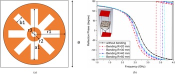
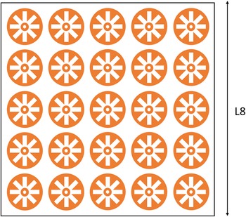
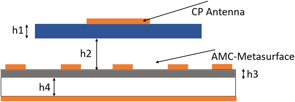
The configuration of AMC unit cell is shown in Fig. 2(a). The proposed AMC unit cell derived from EBG structure, and designed AMC consists of a circular patch with multiple rectangular slots. The AMC structure is designed on polyimide with a dielectric constant of 3.5, a loss tangent of 0.0027, and a thickness h 3 of 0.254 mm. The ground plane of the AMC structure is separated by h 4 = 2.7 mm. Figure 2(b) depicts reflection phase values of AMC unit cell. The AMC ±90° reflection phase bandwidth ranges from 2.1 to 2.8 GHz, with a 0° reflection phase at 2.5 GHz. To study the AMC for wearable applications, we have simulated reflection phase values at various degrees of bending and it is observed that the results of AMC unit cell is considerably good throughout a wide range of bending degrees. The AMC unit cell is durable and well-suited for wearable applications. The AMC metasurface shown in Fig. 3 is comprised of an array of 5 × 5 AMC unit cells.
(a) Top view of AMC unit cell. (b) Reflection phase of AMC unit cell under bent conditions.

Configuration of AMC-based metasurface.

Proposed design integration of CRLH-based antenna and AMC
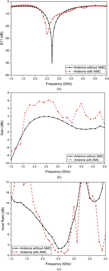
Figure 4 depicts the side view of the proposed antenna, which is a combination of a CRLH-TL-based CP antenna and an AMC metasurface. A 5 × 5 AMC unit cell array is used as in-phase reflector to suppress the effect of the human body on the antenna and increase forward radiation. S parameter results of the antenna with and without AMC reflector are shown in Fig. 5(a). The impedance bandwidth of the antenna without AMC is 2.36–3.1 GHz, whereas the impedance bandwidth of the antenna with AMC is 2.3–3.1 GHz. It is observed that the resonance frequency of the AMC-loaded antenna is slightly shifted to the left side in comparison to the CRLH-based antenna. The simulated gain values of both antennas are shown in Fig. 5(b), with the AMC-loaded antenna exhibiting stable gain within the impedance bandwidth and a peak gain of 6.1 dBi at 2.6 GHz. It is also noticed that the AMC-loaded antenna (2.3–2.8 GHz) exhibits an improved 3 dB ARBW than the CRLH-TL-based antenna. As a result, we can conclude that combining AMC with the CRLH-TL-based CP antenna enhances overall radiation characteristics.
Side view of CRLH-based CP antenna integrated with AMC.

Simulated (a) S 11. (b) Gain. (c) Axial ratio of antenna with and without AMC.

Evaluation of AMC antenna performance under bending conditions
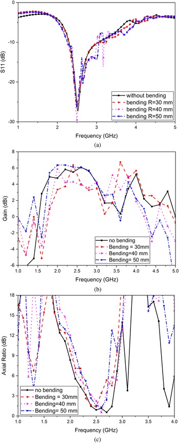
For practical wearable applications, the designed antenna must be able to display robust performance owing to changes in shape caused by the curvature of the human body. Thus, in this section, we have evaluated the performance of proposed AMC antenna by varying its shape as per the requirement. The different AMC antenna combinations under conformal conditions placed on cylinders of varying diameter is designed. The simulated results show that the antenna's S-parameter has minute impact due to variation in sizes, and the antenna is suited for wearable devices. Figure 6(a) shows the simulated reflection coefficients of AMC antenna under different bending conditions and it is observed that impedance bandwidth of AMC antenna almost remain same for R = 30, 40, and 50 mm bending diameter. The simulated gain of the antenna for bending R = 30, 40, and 50 mm is shown in Fig. 6(b); it is observed that as the gain of the antenna reduces, bending diameter reduces. The axial ratio of the AMC antenna is shown in Fig. 6(c) and 3 dB ARBW reduces to 2.35–2.6 GHz for R = 30 mm. It is clear that as bending level increases, the performance of the antenna slightly deteriorates.
Simulated (a) S 11. (b) Gain. (c) Axial ratio of AMC antenna under different conformal cylinder radius.

Experimental results and discussion
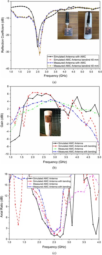
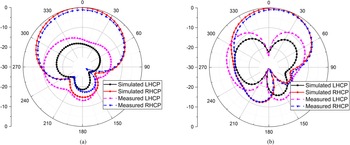
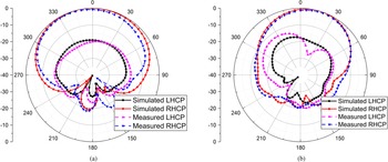
To investigate the bending performance, proposed antenna is positioned on a cylinder (radius = 50 mm) made up of foam material. The radius of foam cylinder is deliberately selected to mimic the antenna's conformation to a typical human arm. Figure 7 shows the photographs of measurement of AMC antenna using vector network analyzer. The measured and simulated S 11 of the antenna are shown in Fig. 7(a). It is observed that the measured bandwidth of AMC antenna is 2.3–3.2 GHz with relative impedance bandwidth of 21%. However, the performance of antenna slightly changes in the conformal shape as the human arm of radius is 50 mm. It is seen that impedance bandwidth of AMC antenna with bending is 2.32–3.1 GHz. Therefore, it is clear that antenna has little effect of bending and is suitable for wearable application. Figure 7(b) shows the simulated and measured gain of the antenna, it is observed that the proposed antenna exhibits stable gain in both planar and conformal forms with peak gain of 5.89 and 5.72 dBi in planar and conformal form, respectively. The axial ratio of the proposed antenna is shown in Fig. 7(c), AMC antenna have 3 dB ARBW of 2.36–2.78 GHz, while 3 dB ARBW of bent AMC antenna is 2.38–2.67 GHz. Further, the normalized radiation patterns of antenna at 2.4 GHz under normal and bent conditions are plotted in Figs 8 and 9, respectively. It has been observed that the proposed antenna LHCP pattern is 15 dB below in comparison with RHCP pattern in the boresight direction. It is seen that HPBW of the AMC antenna and bent AMC antenna is 52° and 45° in phi = 0° plane while HPBW of the AMC antenna and bent AMC antenna is 42° and 41° in phi = 90° plane. Therefore, it is clear that AMC antenna shows stable results in bent form also.
Simulated and measured (a) S 11. (b) Gain. (c) Axial ratio of AMC antenna under normal and bent condition.

Normalized LHCP and RHCP radiation pattern of AMC antenna under normal condition. (a) Phi = 0°. (b) Phi = 90° at 2.4 GHz.

Normalized LHCP and RHCP radiation pattern of AMC antenna under bent condition. (a) Phi = 0°. (b) Phi = 90° at 2.4 GHz.

Performance of the proposed antenna on the human body
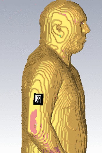
We have executed full-wave simulations with the designed antennas close to a human body model to verify the on-body performance by using human phantom model named Hugo (from CST MWS voxel family). The proposed antenna is placed on the arm of human body phantom as shown in Fig. 10. Instead of modeling the antenna on the complete numerical body model, a reasonable region of Hugo's arm is chosen for simulation to shorten simulation time. In all the studied scenarios, antenna is assumed to be separated from the skin layer by an additional distance of 2 mm to account for clothing.
3-D CST human body model (Hugo).

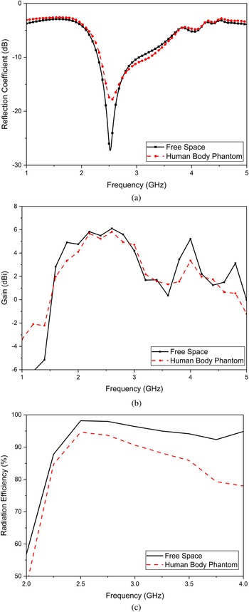
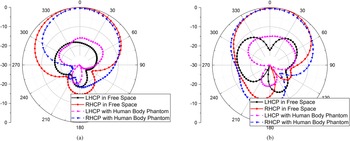
The comparison of simulation results of reflection coefficients of the proposed antenna in free space and with human body model (Hugo) is shown in Fig. 11(a). It is observed that impedance of the proposed antenna is slightly shifted to right side and small bandwidth widening is seen with −10 dB impedance bandwidth of 2.32–3.23 GHz due to the loading of human phantom model and impedance matching of the antenna is also reduced. The reduction is due to high dielectric constant values of different tissue layers of human body model. The gain values of the proposed antenna are shown in Fig. 11(b), and it is seen that implementation of human body model has little impact on antenna gain and radiation efficiency performance. The simulated peak gain of the antenna is reduced to 5.82 as compared to 6 dBi in free space. The radiation efficiency of the proposed antenna is shown in Fig. 11(c) and we can say that radiation efficiency of the antenna is above 85% in the whole impedance bandwidth for both the cases. Figure 12 shows the simulated radiation patterns of the proposed antenna in free space and with human body condition at 2.4 GHz. The results illustrate that radiation characteristics of antenna change trivially between free space and on-body status because of the good isolation achieved by the AMC structure.
Simulated results of the proposed antenna in free space and with human body phantom. (a) Reflection coefficient. (b) Gain. (c) Radiation efficiency.

Simulated normalized radiation patterns of the proposed antenna in free space and with human body phantom. (a) Phi = 0°. (b) Phi = 90°.

SAR results of proposed antenna for wearable safety
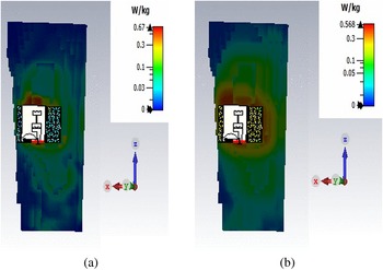
To guarantee compliance with safety laws, the SAR level of a wearable antenna must be evaluated while designing the antenna. Furthermore, SAR is used to assess the risks that wearable antennas pose to human health. Thus, the RF energy received by human tissues must not go over the critical threshold of 1.6 W/kg for any 1 g tissue or 2 W/kg for 10 g tissue, according to the IEEE C95.1-1999 and IEEE C95.1-2005 standards. The AMC antenna is placed on the CST human body model (Hugo) to assess the SAR of the human body. Figure 10 depicts the numerical simulation of a 3-D body with approximate human tissue data. After loading the AMC structure, the EM wave radiation to the human body is effectively reduced. Figure 13 depicts the simulated SAR distribution on human hand. From Fig. 13(a) it is seen that at 2.4 GHz, the maximum value of SAR is 0.67 W/kg of 1 g/m3 under the condition of 1 W input power. Further, Fig. 13(b) depicts the SAR distribution for 10 g human body tissue and it is observed that peak SAR value is 0.568 W/kg of 10 g/m3.
SAR simulation. (a) 1 g human tissue. (b) 10 g human tissue at 2.4 GHz.

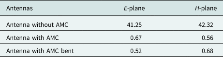
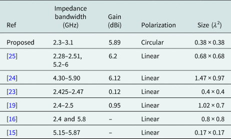
Table 2 depicts the SAR simulation at 2.4 GHz, as shown in the table below. The AMC antenna's assessed SAR values are all considerably below the regulated SAR criteria, but the monopole antenna does not. The reason for this is that antenna without AMC produces an omnidirectional pattern, but an AMC antenna produces a directing radiation pattern. The SAR study demonstrates the AMC antenna's advantage for operating close to the human body. A comparison of the proposed work with the work discussed in literature is presented in Table 3. It is seen that the proposed antenna has smaller foot print with stable gain as compared to the work reported. The proposed AMC antenna exhibits circular polarization which makes it a good candidate for ISM band wearable applications.
SAR analysis of antennas at 2.4 GHz (1 g tissue (w/kg))

Comparison of the proposed work with the previous work

Conclusion
A CRLH-TL-inspired compact CP antenna is presented. For wearable antenna applications, the proposed CP antenna is backed by an AMC-based metasurface. The developed AMC antenna has an impedance bandwidth of 21% (2.3–3.2 GHz) and a gain of 5.89 dBi. Numerical calculations and experimental results have also demonstrated that the designed AMC-based antenna works well in terms of radiation performance in conditions of minor modifications due to structural deformation such as bending, as well as human body loading effects. Furthermore, the AMC reflector significantly minimizes SAR values, making the AMC antenna performance better than a single CRLH-TL-based CP antenna.
Data
The datasets generated during and/or analyzed during the current study are available from the corresponding author on reasonable request.
Acknowledgements
Special thanks to Prof. Binod Kumar Kanaujia, NIT, Jalandhar for support this work.
Author contributions
All authors contributed to the study conception and design. Software simulation and analysis were performed by Mohammad Hussain Abbas and Ankit Sharma. The first draft of the manuscript was written by Mohammad Hussain Abbas and the manuscript was revised by Deepak Gangwar and Shamsher Singh. All authors read and approved the final manuscript.
Financial support
None.
Conflict of interest
None.
 Mohammad Hussain Abbas is currently pursuing Ph.D. in electronics engineering from the University Institute of Engineering and Technology, Maharshi Dayanand University, Rohtak, India. At present his research interest includes metasurfaces, THz antennas, circularly polarized antennas, reconfigurable antennas, and radar cross section reduction of antennas.
 Dr. Shamsher Singh earned M.Sc. in electronics in very-large-scale integration (VLSI) and instrumentation engineering in 2002 from Kurukshetra University, Kurushetra, India, and also earned M.Tech. in electronics and communications engineering in 2006, and a Ph.D. in electronics engineering from Maharshi Dayanand University (MDU), Rohtak, Haryana, India. He is currently working as an assistant professor with the Department of Electronics and Communication Engineering, MDU, Rohtak. He has published more than 20 research papers in refereed international journals and conferences. He had supervised several M.Tech. and B.Tech. students in the field of microwave and VLSI designing. His current research interest includes VLSI designing, instrumentation, metasurfaces, circularly polarized antennas and radar cross section reduction of antennas.
 Ankit Sharma earned B.Tech. in electronics & instrumentation engineering, in 2008, and an M.Tech. in signal processing, in 2012 from Ambedkar Institute of Advanced Communication Technologies and Research, Delhi, India and a Ph.D. in electronics engineering from Indian Institute of Technology (Indian School of Mines), Dhanbad, India. He is currently working as an associate professor with the Department of Electronics and Communication Engineering, Galgotias College of Engineering and Technology, Greater Noida. He has published more than 20 research papers in refereed international journals and conferences. He had supervised several M.Tech. and B.Tech students in the field of radio frequency and microwave engineering. His current research interest includes metamaterials, metasurfaces, THz antennas, circularly polarized antennas, characteristics mode analysis, substrate integrated waveguides, reconfigurable antennas, and radar cross section reduction of antennas.
 Deepak Gangwar earned B.Tech. from Uttar Pradesh Technical University, Lucknow, India, in 2008, and an M.Tech. from Guru Gobind Singh Indraprastha University, Delhi, India in 2011. He obtained a Ph.D. in electronics engineering from Indian Institute of Technology (Indian School of Mines), Dhanbad, India. Currently, he is working as professor in Bharati Vidyapeeth's College of Engineering, New Delhi, India. His research interest includes metamaterial-based antennas, ultra-wideband antennas, metamaterial filters, frequency selective surface, metasurface, and radar cross section reduction.