1. Introduction
Next-generation wireless devices are aiming for significant expansion in terms of data rates, frequency spectrum coverage along with reduced form factor. It is expected that a radio device may contain more than 10 different radios and 20 antennas operating across a wide frequency range, and it needs to comply with several radio standards [Reference Vainikainen, Holopainen, Icheln, Kivekas, Kyro, Mustonen, Ranvier, Valkonen and Villanen1]. These features are addressed with a multi-antenna system approach, such as the multiple input multiple output (MIMO) technique that provides higher data capacity, and frequency-reconfigurable techniques for multi-band and wide-band operation. In particular, the MIMO technique aims for efficient operation with reduced envelope correlation coefficient (ECC) while the frequency reconfigurable or tunable antennas target for enhanced total efficiency. In fact, the typical frequency reconfiguration methods, such as PIN diodes [Reference Jin, Deng, Yang, Xu and Liao2–Reference Abutarboush, Nilavalan, Cheung, Nasr, Peter, Budimir and Al-Raweshidy7], varactor diodes [Reference Sun, Cheung and Yuk8–Reference Riaz, Zhao and Geng11], radio frequency microelectromechanical systems (RF MEMS) [Reference Kim and Rahmat-Samii12–Reference Molinero, Aghaei, Morris and Cunningham17], and RF switches [Reference Valkonen, Luxey, Holopainen, Icheln and Vainikainen14, Reference Cetinoneri, Atesal and Rebeiz18–Reference Valkonen, Ilvonen, Icheln and Vainikainen22] currently provide narrow band solutions. Moreover, these solutions suffer from power consumption, non-linearity, and form factor issues. With the continuous demand for additional frequency band coverage and higher data rates, it is becoming an arduous task to accommodate the increasing number of antennas in a limited volume of a mobile device.
Lately, a multiantenna system method was reported in [Reference Hannula, Saarinen, Holopainen and Viikari23], where the antenna frequency response is entirely tuned by manipulating the feeding signal characteristics such as amplitude and phase of antenna feeds. The concept is based on mutual coupling among antenna elements, and utilize optimal feeding weights in order to tune the antenna to a desired operation frequency. It may resemble to beamforming in antenna arrays where similar weighted feeds steer the main beam, however, this approach adjusts the frequency characteristics of the antenna cluster. The concept is initially verified at 2 and 4.3 GHz with four monopole antenna clusters where the weighted signal generation is realized as a static solution based on transmission line-based power dividers and phase shifters [Reference Hannula, Saarinen, Holopainen and Viikari23]. To cope with this limitation, an RF-integrated transmitter circuit is implemented to support on-chip weighted signal generation capabilities in order to verify the antenna tuning concept across a wide band from 1.5 to 5 GHz [Reference Saleem, Stadius, Hannula, Lehtovuori, Kosunen, Viikari and Ryynänen24]. Afterward, the MIMO concept has advanced as a feature to the antenna cluster tuning concept [Reference Tian, Lau and Ying30]. The scenario is illustrated in Fig. 1(a) where weighted antenna feeds $( A_{1-n},\; \, \varphi _{1-n})$ are applied to $N$
 clusters operating as MIMO with $k$
 elements in each cluster. However, both MIMO and antenna cluster tuning are limited in a sense that the optimal signal generation was realized in a computational software tool, such as, Matlab where mathematical manipulation was done to scale amplitude and phase of antenna cluster feeds.
Illustration of a multiport antenna cluster tuning concept with $N$ MIMO antennas with $k$
 elements in each cluster. (a) Ideal weighted sources for frequency tunability of MIMO antenna clusters. (b) Proposed on-chip weighted signal generation implementation for frequency-reconfigurable operation of MIMO clusters.

In this detailed work, an extension to [Reference Saleem, Luomaniemi, Lehtovuori, Stadius, Kosunen, Viikari and Ryynänen26], we represent a system where a handset MIMO antenna is fed by a 0.5–4.5 GHz transmitter front-end to implement a frequency reconfigurable multiport antenna cluster. The MIMO work in [Reference Tian, Lau and Ying30] is extended with the transmitter IC [Reference Saleem, Stadius, Hannula, Lehtovuori, Kosunen, Viikari and Ryynänen24] as a possible alternative to frequency reconfigurable MIMO antenna cluster. In contrast to [Reference Saleem, Stadius, Hannula, Lehtovuori, Kosunen, Viikari and Ryynänen24], the operation of transmitter IC is extended to cover frequency bands from 0.5 to 1.5 GHz, and the transmitter IC is capable of tuning four antenna clusters operating from 0.5 to 4.5 GHz. The goal here is to verify antenna cluster tuning and MIMO features with a real transmitter circuit with on-chip amplitude and phase weighting capabilities as shown in Fig. 1(b). It shows a compact real-time solution for on-chip weighted signal generation for $N$ antenna clusters with each being driven with a respective on-chip tuning circuit. Furthermore, the verification of both abovementioned concepts requires non-traditional anechoic chamber measurements which includes an active real-time transmitter IC driving antenna clusters operating as MIMO. This customized measurement procedure is developed and discussed with respect to traditional antenna measurements. This is among the first demonstrations of MIMO antenna clusters controlled by a multi-channel IC enabling wide-band matching and frequency reconfigurability across the spectrum. The paper is organized as follows. Section “Implementation of the antenna-IC system” provides brief review of MIMO antenna clusters utilized in this work, and the RFIC operation and circuit details. Section “Measurement procedure” highlights the measurement procedure adopted for the verification and performance evaluation of the MIMO cluster. Section “Measurement setup” presents the measurement setup, and the result for the four antenna clusters operating as a MIMO with or without the transmitter IC across the spectrum are discussed in Section “Results and discussion.” Finally, the conclusions are given in the final section.
2. Implementation of the antenna-IC system
2.1. Antenna design
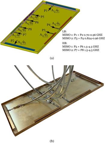
In this work, we use the antenna design originally presented in [Reference Tian, Lau and Ying30] and is depicted in Fig. 2. This platform presents the challenges set by the requirements of modern smartphones but also demonstrates the benefits achievable with the antenna cluster technique. With large touchscreen taking almost all of the front face of the device, there is very little volume available for the antennas, especially in the low-band frequencies where larger elements are needed for good performance. Also, for esthetic reasons, as well as for mechanical durability, metallic rims are very popular. In this case, we use completely unbroken rim which is even more challenging environment than typically used rims divided with slots. The unbroken rim tends to increase coupling between the antennas making the realization of MIMO operation very challenging.
(a) Simulated antenna structure and the port configurations. Antenna elements of the clusters are indicated with the same color. (b) The measured antenna prototype.

We utilize the radiation modes of the rim excited with multiple elements placed around the device. Because of the high coupling, the performance of traditional antenna solutions would deteriorate, but by using the antenna cluster technique, we can benefit from this coupling because relatively high level of coupling is typically required for good cluster performance [Reference Hannula, Lehtovuori, Luomaniemi, Saarinen and Viikari27]. In this design, each cluster has two elements. When these elements are fed with properly chosen complex signals:

the reflections from the ports can be minimized and the radiated power maximized. By varying the feeding weights as a function of operation frequency, the efficiency across wide frequency bands can be maximized.
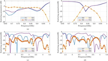
The antenna system consists of total of eight elements which are used as four antenna clusters as shown in Fig. 2. These elements are tuned to specific frequency bands with lumped matching components in order to cover frequency spectrum from 0.5 to 4.5 GHz. Two clusters are designed for the low band (LB). The first LB-cluster (LB1) covers a wider 700–960 MHz band with one MIMO antenna and the second LB-cluster (LB2) achieves a narrower 824–960 MHz band to form a two-element MIMO system as illustrated in Figs 3(a) and 3(b). The two high-frequency clusters are used to cover a very wide band of 1.5–4.5 GHz with two-element MIMO, and denoted by high band (HB) clusters.
Measured scattering parameters of LB and HB-clusters: (a) LB1 (port 1+port 2) (700–960 MHz), (b) LB2 (port 3+port 4) (824–960 MHz), and (c), (d) HB1 (port 5+port 6)+HB2 (port 7+port 8) (1.3–4.5 GHz).

The optimal feeding weights (${\bf a} = A_{i}\angle \varphi _{i}$ ) are obtained from the mathematical framework of antenna cluster tuning [Reference Hannula, Saarinen, Holopainen and Viikari23] which states that an optimal excitation a can be extracted from the antenna scattering parameters S while reducing the reflections at the antenna cluster feeds. In other words, the antenna cluster tuning or matching efficiency ($\eta _{match}$
 ) is maximum for optimal feeding weights a which pours down to maximizing the Rayleigh's quotient in equation (2). The antenna structure uses 0.8 mm Rogers RO4003C ($\epsilon _{r} = 3.38,\; \, \tan \delta = 0.0021$
 ) low-loss substrate and offers high value of radiation efficiency $( \eta _{rad})$
 . The antenna matching efficiency $( \eta _{match})$
 and Rayleigh's quotient in (2) can be maximized in order to extract required weighted signal characteristics. For low-loss antennas in a lossless environment, total efficiency of antenna is close to matching efficient. On the other side, the MIMO performance metric is known as envelope correlation coefficient (ECC) which can be determined based on the far-field radiation patterns of the antenna clusters operating as MIMO. The ECC metric can be described as shown in equation (3) where far-field intensities of two antenna clusters are denoted by $\overrightarrow {E_{1}}$
 and $\overrightarrow {E_{2}}$
 in a spherical coordinate system:


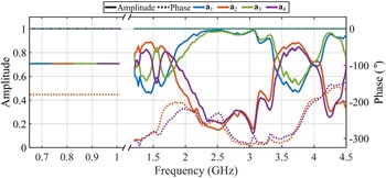
Figure 4 shows the optimal feeding weights for both the low-band and the high-band operations extracted from equation (2). These results show the two different ways the cluster technique can be utilized. In LB clusters, the power is divided equally between the ports and either a 0$^{\circ }$ or 180$^{\circ }$
 phase difference is applied to improve the excitation of the metal-rim modes. In HB-clusters, we can recognize two different operation modes. Around 1.7and 3.5 GHz both elements are used, whereas between these bands, only one of the elements is mainly used. This allows us to extend the frequency range of the cluster by combining the operation of two elements with partly overlapping resonances.
Optimal feeding weights for all four antenna clusters operating in LB and HB.

2.2. IC design
For the antenna cluster operating as a MIMO, an integrated RF transmitter is required to generate on-chip complex feeding weights. In particular, the target for the IC is to comply with the respective amplitude and phase characteristics shown in Fig. 4. First, the LB1 and LB2 clusters operate from 700 to 960 MHz, and require equal feeding signal amplitudes with $0^{\circ }$ or $180^{\circ }$
 phase difference among antenna elements. Second, the HB1 and HB2 clusters have varying amplitude and phase properties, i.e. 14 dB amplitude range and $0$
 – $250^{\circ }$
 phase difference are desired for each antenna element operating from 1.3 to 4.5 GHz.
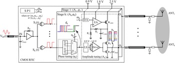
To cope with these aforementioned requirements, an RFIC prototype has been utilized in this work, originally demonstrated in [Reference Saleem, Stadius, Hannula, Lehtovuori, Kosunen, Viikari and Ryynänen24] for the first time in conjunction with antenna cluster tuning concept. In contrast to [Reference Saleem, Stadius, Hannula, Lehtovuori, Kosunen, Viikari and Ryynänen24], in this work the RFIC additionally covers low-band frequencies 700–960 MHz, and also 1–1.5 GHz frequency range for high band clusters. Figure 5 shows the system level diagram of the CMOS RFIC used in this contribution. In general, it consists of an input buffer stage and $k$ tuning stages corresponding to $k$
 antenna elements in each antenna cluster. The IC takes an RF tone ranging between 0.7 and 4.5 GHz as an input, and transforms it to RF pulses $S_{1} - S_{k}$
 with buffer stages. Then, these pulses are fed to each tuning stage which basically contains a phase-tuning block followed by an amplitude tuning block. These pulses are first processed in the phase-tuning block $\varphi _{k}$
 which employs delay tuning circuits for the phase tuning represented with $d_{k}$
 . The phase-tuned signal $d_{k}$
 is then scaled by the amplitude tuning block $A_{k}$
 which incorporates the low drop-out regulator-based supply scaling for the output $O_{k}$
 . In this prototype ($k = 2$
 ), the RFIC outputs are wirebonded to a printed circuit board (PCB) connecting IC outputs to the antenna clusters reported in [Reference Tian, Lau and Ying30]. The PCB is realized on a low loss 0.154 mm Rogers RO4350B substrate ($\epsilon _{r} = 3.48,\; \, \tan \delta = 0.0031$
 ). The effect of IC output pad capacitance, bondwire inductance, and PCB traces have been taken into account during design procedure with an EM simulation model so that the off-chip losses and deviations are accordingly compensated.
System level diagram of a generic CMOS multichannel RFIC consisting of $k$ stages for the tuning of the MIMO antenna cluster. An RF signal $V_{RF}( t)$
 is driving each tuning stage where the $k$
 -th tuning stage weights the phase and amplitude of the $k$
 -th antenna element in accordance with the optimal phases and amplitudes. In particular, each tuning stage contains a corresponding phase-tuning block $( \varphi _{k})$
 and an amplitude tuning block $( A_{k})$
 with resolutions $n_{k}$
 and $m_{k}$
 respectively.

The detailed amplitude and phase-tuning methodologies are presented in [Reference Saleem, Stadius, Hannula, Lehtovuori, Kosunen, Viikari and Ryynänen24]. The weighted signals $O_{1} - O_{k}$ have certain resolutions for phase-tuning and amplitude tuning at spectrum boundaries. The amplitude and phase or delay scaling capabilities of the transmitter IC are presented in Fig. 6(a) where transmitter IC operation at 0.5 and 5 GHz are presented with the on-chip amplitude scaling performance in relation to the simulation results. The measured amplitude scaling range deviates slightly due to losses occurring at higher frequency ranges. The transmitter RFIC provides an amplitude range of 10–18 dB at each IC output $O_{1} - O_{k}$
 with an amplitude resolution of 0.6–1 dB across the band of interest. Similarly, the RFIC provides a phase coverage of $360^{\circ }$
 where each phase-tuning block $\varphi _{1} - \varphi _{k}$
 enable $3$
 and $20^{\circ }$
 phase resolutions at 700 MHz and 4.5 GHz, respectively. The phase-tuning circuit consists of tapped-delay line circuit similar to [Reference Lemberg, Martelius, Roverato, Antonov, Nieminen, Stadius, Anttila, Valkama, Kosunen and Ryynänen28], and the measured delay characteristics in Fig. 6(b) illustrate that each on-chip delay tuning circuit provides a delay range of 830 ps which is an ample amount of delay tuning fulfilling our feeding weight requirements. Furthermore, the LB1 and LB2 clusters require constant amplitude and phase difference settings for the low bands (700–960 MHz), there the resolution aspect has a marginal effect. For the HB1 and HB2 clusters (1.5–4.5 GHz), the varying amplitude and phase difference requirements seem to demand sufficient resolution. Nevertheless, the high-band clusters mainly operate in an alternate manner and require one antenna element of the cluster to be the major contributor in a particular band. This in turn relaxes the amplitude and phase-tuning specification requirements for the on-chip implementation.
RFIC transmitter incorporating on-chip weighted signal generation. (a) Measured amplitude scaling range of one TX IC output. (b) Measured delay tuning performance of two TX IC phase-tuning blocks.

3. Measurement procedure
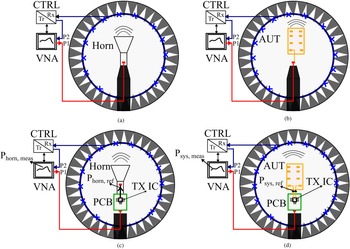
Traditionally, antenna under test (AUT) performance is characterized inside an anechoic chamber where initially a gain calibration procedure is performed with a standard antenna, of which the gain is known accurately [Reference Harish29]. For the purpose of gain calibration, a broadband horn antenna structure is placed inside an anechoic chamber as shown in Fig. 7(a). One port of a vector network analyzer (VNA) excites the horn antenna whose radiation pattern is then captured by the scanning probe array embedded inside the anechoic chamber. The control unit (CTRL) interfaces with this scanning array and completes the path by connect it to the second port of the VNA. In this way, we are able to model the anechoic chamber environment with a standard gain calibration data. Afterward, the horn antenna is removed, and the actual AUT is placed inside the chamber as shown in Fig. 7(b). Again, the same procedure is performed with an exception, the gain calibration done prior to this step act as a reference measurement for AUT characterization. Hence, the required performance metrics such as gain, directivity, efficiency, radiation patterns, etc. are determined in accordance with that reference measurement relying on post processing of measurement data.
Comparison of gain calibration and AUT characterization in an anechoic chamber consisting of a compact field scanner capable of performing accurate near-field to far-field transformation. (a) Gain calibration procedure with a broadband horn antenna driven with a VNA and control unit CTRL, an apriori for AUT measurement. (b) Traditional passive AUT characterization setup where clusters are being characterized individually. (c) Gain calibration with an active TX IC where each feed of the TX IC is separately interfaced and characterized with horn antenna. (d) Active AUT measurements involving a TX IC providing real-time weighted RF signal generation for antenna cluster tunability and MIMO operation verification.

In prior work reported in [Reference Tian, Lau and Ying30], the complex feeding weights have been realized by measuring the radiation patterns of each feed individually while terminating the other feeds with 50$\, \Omega$ loads and then combining these patterns numerically in software tool Matlab where proper amplitude and phase weighting were accomplished. Because of the weight generation on RFIC realized in this work, we can measure all the feeds of a cluster at once with respective on-chip amplitude and phase scaling. Because the measurement system does not directly support the use of an active IC in the measurements, we have performed supplementary steps in order to calibrate the results. Therefore, the anechoic chamber measurements have to be customized, and for this purpose a new setup is illustrated in Fig. 7(c) which includes the TX IC driving a standard horn antenna. Then, the gain calibration procedure is performed for each TX IC output $O_{1} - O_{k}$
 in order to export reference measurement data for AUT characterization. Similarly, the horn is replaced with the AUT and by generating the respective serial-to-peripheral interface (SPI) settings $( m,\; \, n)$
 based on Fig. 4, one can generate weighted signals at the TX IC outputs which are driving the antenna clusters on the handset AUT. In this way, the AUT performance metrics can be determined in real time where all antenna cluster feeds are excited at once with actual weighted RF signals. The customized antenna cluster measurement procedure is stated below:
(1) TX IC amplitude and phase scaling range and resolutions are characterized in reference to a 50$\, \Omega$
 load as depicted in Fig. 6.
(2) Gain calibration procedure with a horn antenna should be separately performed with each TX IC output $O_{1} - O_{k}$
. For this purpose, VNA port 1 sweeps TX IC input signal across the designated frequency range, and the SPI setting for amplitude tuning control $m$ is set to the highest code value, i.e. $m_{1}-m_{k} = 15$. This implies that the TX IC output drives the horn antenna with a maximum deliverable power whose radiation pattern is then captured with the scanning probes interfacing with VNA port 2 as shown in Fig. 7 (c). This reference measurement consists of gain calibration data, and are denoted with $\{ P_{horn, 1},\; \, \ldots ,\; \, P_{horn, k}\}$ corresponding to each TX IC output $O_{1} - O_{k}$. Since all amplitude tuning blocks $A_{1} - A_{k}$ are identical, i.e. the calibration data is also similar which allows us to use a single reference measurement: $P_{horn, meas}\, ( {\rm dB}) = {\rm average}( \{ P_{horn, 1},\; \, \ldots ,\; \, P_{horn, k}\}$).(3) Next, replace the horn antenna with AUT, and connect TX IC outputs $O_{1} - O_{k}$
to respective antenna cluster ports. The VNA port 1 sweeps TX IC input signal either in LB or HB depending on the respective antenna clusters. Apply SPI settings $( m,\; \, n)$ based on Fig. 4 in order to perform antenna cluster tuning. This measurement provides transmission data from our TX IC driving AUT which is captured by VNA port 2, and denoted by $P_{sys, meas}$ (dB).(4) Steps (2) and (3) provide relative performance metrics $P_{horn, meas}$
(dB) and $P_{sys, meas}$ (dB) which models the complete transmission path between VNA ports 1 and 2. To observe antenna cluster tuning of AUT based on weighted signal generation with TX IC, the total efficiency $\eta _{tot}$ requires absolute power being fed to horn and AUT. In this way, the AUT LB and HB clusters can be characterized with appropriate efficiency metric. Thus, the AUT efficiency is described by equation (4) where $P_{horn, ref}$ (dBm) and $P_{sys, ref}$ (dBm) denote the absolute power delivered to horn and AUT, respectively. These power levels are determined from a benchmark simulation performed in an IC design environment where the measured scattering parameters of the AUT and horn antennas are imported, and then simulated with TX IC design at the transistor level. The reasons to obtain these numbers are three fold: first, the simulations take into account transmission line, substrate, and cable losses through EM based models. Second, the AUT uses matching networks for LB and HB clusters which results in different output power levels across various frequency bands. Finally, the proprietary measurement environment was limited to passive antenna measurements only, and while now we can execute active antenna measurements as well:(4)$$\eqalign{\eta_{tot}\, {\rm ( dB) }& = \overbrace{[ P_{sys, \, meas}\, {\rm ( dB) }-P_{horn, \, meas}\, {\rm ( dB) }] }^{{\rm Measured\ relative\ power\ }}\cr & - \underbrace{[ P_{sys, \, ref}\, {\rm ( dBm) } - P_{horn, \, ref}\, {\rm ( dBm) }] }_{{\rm Input\ power\ reference}}}$$








4. Measurement setup
The operation of the whole system is confirmed with measurements. The measurements are performed with an MVG StarLab 6 GHz antenna measurement system, a compact field scanner which enables sub-6 GHz antenna characterization. Basically, it is designed for passive antenna measurements, however, a custom measurement procedure is adopted to accommodate active antenna measurements.
For this purpose, the TX IC input is connected to one port of the VNA and the TX IC output $O_{k}$ is connected to horn antenna. Then, this system (TX IC + HORN) is placed inside the StarLab equipment where one VNA port sweeps the IC input signal over 0.7–4.5 GHz. Accordingly, the horn antenna radiation pattern is scanned by the equipment scanning probe which is connected to second port of the VNA. In this way, we have measured data of IC output $O_{k}$
 with the horn antenna as a reference. Similarly, all IC outputs $O_{1} - O_{k}$
 have been separately characterized for calibration purpose.
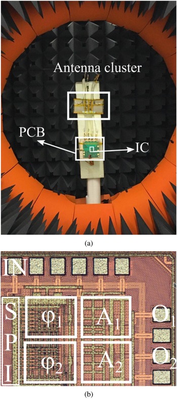
Thereafter, the actual antenna cluster ports are attached to the PCB, and the complete system (TX IC + AUT) is mounted inside MVG StarLab 6 GHz equipment in order to investigate the efficiency of all four antenna clusters as shown in Fig. 8(a). To determine the respective antenna cluster efficiency, one VNA port sweeps the TX IC input and the antenna cluster ports are attached to two IC outputs $O_{1} - O_{2}$ with respective amplitude and phase settings controlled with a SPI for proper weighting of antenna cluster feeds. Figure 8(b) shows the die photo of the multichannel TX IC with the corresponding amplitude $A_{1}-A_{2}$
 and phase-tuning blocks $\varphi _{1}-\varphi _{2}$
 . As mentioned previously, the antenna cluster radiation pattern is scanned by the probes inside the equipment and connected to the second port of the VNA. As a consequence, the equipment software processes the measurement data and enables antenna cluster efficiency characterization across desired spectrum.
(a) Measurement setup. (b) Chip photo.

5. Results and discussion
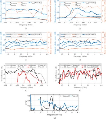
The measurement results for the LB clusters are shown in Figs 9(a), 9(b), 9(e), and the HB clusters in Figs 9(c), 9(d), 9(f). The results are presented both for the combined antenna-IC operation and without the IC for comparison. The results of the antenna only are obtained by measuring each feed separately and combining these patterns computationally with the proper weighting coefficients.
Measured characteristics of all four clusters in reference to input power levels across the designated frequency spectrum. (a), (b) LB1 and LB2 cluster characteristics from 0.65 to 0.9 GHz. (c), (d) HB1 and HB2 cluster characteristics from 1.3to 4.5 GHz. (e) LB-cluster performance with/without IC. (f) HB-cluster performance with/without IC. (g) ECC of the LB and HB-clusters from 0.65 to 4.5 GHz.

The total efficiency of the antenna cluster is roughly constant for LB1 cluster while the LB2 cluster offers a bandpass type response, and the efficiency of the cluster lies between $-4$ to $-1.5$
 dB. For LB1 cluster, the results show that up to 900 MHz, the results are very similar. For LB2 cluster, there is a frequency shift of about 50 MHz, nevertheless, the efficiency level and bandwidth are otherwise similar between the two results. To investigate the issue, the PCB transmission lines and the antenna cluster models are analyzed in ADS software with $S$
 -parameter simulation. It confirms that the frequency shift owes to PCB transmission lines between the IC and antenna PCBs which were neglected during the design phase. This could be compensated relatively easily, e.g. by changing the matching network component accordingly.
The high-band results of clusters 1 and 2 show that very wide operation band from 1.5 up to 4.5 GHz can be achieved also with the IC. Both HB1 and HB2 clusters have better than $-3.9$ dB efficiency on average over this band. Some differences between the two cluster results and between the results with and without the IC can be observed. These could be explained, e.g. by non-ideal weighting coefficients, especially for the phase. The feeding weights realized with the IC are based directly on those calculated from the measurement results of the antenna only. When the IC–PCB and the antenna prototype are connected, as shown in Fig. 8, the required feeding weights for the optimal performance might differ from those actually used. These problems could be avoided in the future by improving the integration of the antenna and the IC, for example, by realizing them on the same PCB.
To confirm the important in MIMO operation, the ECC calculated from the measured far-field patterns is given in Fig. 9(g). The results show that especially in the low band, ECC is very low, below 0.1. In the higher frequencies, the ECC values are higher than in the low band, but still below 0.4 in the whole 1.5–4.5 GHz band. This means that the effect of correlation for the MIMO operation is small and good MIMO operation can be achieved in both frequency bands [Reference Tian, Lau and Ying30].
Because the goal of this work is to demonstrate the use of an integrated transmitter IC with a multiport antenna prototype, comparing the results with other published antennas is not straightforward, since they are measured passively without a real transmitter circuit. However, we can compare our results at the general level with some of the other published unbroken metal rim antennas, e.g.[Reference Deng, Feng and Hum31–Reference Qiu and Feng37]. These results show that many of them have larger ground clearances and not as wide frequency bands as this work. In addition, not all of them have MIMO capability and the achieved efficiency levels, taken these factors also into account, are not significantly higher. Therefore, it can be concluded that the proposed solution can offer a competitive performance even with real transmitter circuit combined with the antenna.
6. Conclusion
This paper presents real-time demonstration of transmitter IC enabling frequency tunability of a MIMO handset terminal antennas operating across a wide band in practice. The transmitter IC provides on-chip weighted signal generation in sub-6 GHz frequency bands especially in the low (700–960 MHz) and high bands (1.5–4.5 GHz). The four antenna clusters are driven with optimal signal generation on the implemented transmitter IC. The transmitter IC is fabricated on a 28-nm CMOS process, and accommodates on-chip amplitude and phase-tuning blocks fulfilling the required weighted signal requirements. Traditional passive antenna measurements are compared with the proposed customized antenna measurements where transmitter IC and AUT is used as a system in order to validate the frequency tunability and MIMO operation of antenna clusters. The transmitter IC provides a robust solution in adjusting the frequency characteristics of antenna clusters while providing measured total antenna efficiencies ranging from $-6.5$ to $-1.5$
 dB across wide frequency bands. Competent MIMO performance is achieved with ECC values lower than 0.4 at all frequencies. Hence, this experimental verification confirms the feasibility of an integrated transmitter IC-based solution suitable for antenna cluster-tuning-based MIMO handset devices.
 Ali Raza Saleem was born in Lahore, Pakistan, in 1990. He received his B.Sc. electrical engineering degree in 2014 from the University of Engineering and Technology, Lahore, Pakistan. Later, he received his M.Sc. and Ph.D. degrees in electrical engineering from Aalto University, Finland, in 2017 and 2022, respectively. From 2016 to 2021, he has been working as a research assistant at Aalto University. His research interests include radio frequency-integrated circuits for next-generation radio transceivers, multiport antenna tuning, and 5G-integrated transmitters. Since, 2022 he has been with CoreHW Finland as a design engineer, working on IC design for RF and millimeter wave applications.
 Rasmus Luomaniemi was born in Salo, Finland, in 1994. He received his B.Sc. (Tech.), M.Sc. (Tech.), and D.Sc. (Tech.) degrees in electrical engineering from Aalto University, Espoo, Finland, in 2016, 2018, and 2021, respectively. From 2014 to 2021, he was with the Department of Electronics and Nanoengineering, School of Electrical Engineering, Aalto University, where he studied MIMO antennas for mobile devices and multiport antennas. Since 2021, he has been with Huawei Technologies Finland as a Terminal Antenna Engineer. Dr. Luomaniemi was a recipient of the Second Prize in the IEEE AP-S Student Design Contest as a part of the Team Aalto ELEC, in 2016.
 Anu Lehtovuori received her M.Sc. (Tech.) and Lic.Sc. (Tech.) degrees from the Helsinki University of Technology, Espoo, Finland, in 2000 and 2003, respectively, and her D.Sc. (Tech.) degree from Aalto University, Espoo, in 2015, all in electrical engineering. She is currently a Senior University Lecturer in circuit theory with the Aalto University School of Electrical Engineering, Espoo. Her current research interests include electrically small antennas, multiport antennas, and design of antennas for mobile devices.
 Kari Stadius received his M.Sc., Lic. Tech., and Doctor of Science degrees in electrical engineering from the Helsinki University of Technology, Helsinki, Finland, in 1994, 1997, and 2010, respectively. He is currently working as a staff scientist at the Department of Electronics and Nanoengineering, Aalto University School of Electrical Engineering. His research interests include RF and microwave circuits for communications, and analog and mixed-mode pt"]?>circuit design. He has authored or co-authored over a hundred refereed journal and conference papers, and he holds several patents.
 Marko Kosunen received his M.Sc., L.Sc., and D.Sc. (with honors) degrees from the Helsinki University of Technology, Espoo, Finland, in 1998, 2001, and 2006, respectively. He is currently a Senior Researcher at Aalto University, Department of Electronics and Nanoengineering. In 2017–2019 he visited Berkeley Wireless Research Center, UC Berkeley, on Marie Sklodowska-Curie grant from European Union. He has authored and co-authored more than 90 journal and conference papers and holds several patents. His current research interests include programmatic circuit design methodologies, digital intensive and time-based transceiver circuits, and medical sensor electronics.
 Ville Viikari was born in Espoo, Finland, in 1979. He received his Master of Science (Tech.) and Doctor of Science (Tech.) (with distinction) degrees in electrical engineering from the Helsinki University of Technology (TKK), Espoo, Finland, in 2004 and 2007, respectively. He is currently an Associate Professor and Deputy Head of Department with the Aalto University School of Electrical Engineering, Espoo, Finland. From 2001 to 2007, he was with the Radio Laboratory, TKK, where he studied antenna measurement techniques at submillimeter wavelengths and antenna pattern correction techniques. From 2007 to 2012, he was a Research Scientist and a Senior Scientist with the VTT Technical Research Centre, Espoo, Finland, where his research included wireless sensors, RFID, radar applications, MEMS, and microwave sensors. His current research interests include antennas for mobile networks, RF-powered devices, and antenna measurement techniques. Dr. Viikari has served as the chair of the Technical Program Committee of the ESA Workshop on Millimeter-Wave Technology and Applications and the Global Symposium on Millimeter Waves (GSMM) twice, in 2011 and 2016 in Espoo, Finland. He was the recipient of the Young Researcher Award of the year 2014, presented by the Finnish Foundation for Technology Promotion, IEEE Sensors Council 2010 Early Career Gold Award, the 2008 Young Scientist Award of the URSI XXXI Finnish Convention on Radio Science, Espoo, Finland, and the Best Student Paper Award of the annual symposium of the Antenna Measurement Techniques Association, Newport, RI, USA (October 30–November 4, 2005).
 Jussi Ryynanän was born in Ilmajoki, Finland, in 1973. He received his M.Sc. and D.Sc. degrees in electrical engineering from the Helsinki University of Technology, Espoo, Finland, in 1998 and 2004, respectively. He is a full professor and the Head of the Department of Electronics and Nanoengineering, Aalto University, Espoo, Finland. He has authored or co-authored more than 140 refereed journal and conference papers in analog and RF circuit design. He holds seven patents on RF circuits. His research interests are integrated transceiver circuits for wireless applications. Prof. Ryynänen has served as a TPC Member for the European Solid-State Circuits Conference (ESSCIRC) and the IEEE International Solid-State Circuits Conference (ISSCC), and as a Guest Editor for the IEEE Journal of Solid-State Circuits.