I. INTRODUCTION
Materials with ultrafine grained (UFG) microstructure have appealing properties when compared with those of conventional materials. Reference Gleiter1,Reference Siegel2 These UFG materials produced by severe plastic deformation (SPD) processes were found to possess enhanced physical and mechanical properties (high strength and damping), lower temperature superplasticity, elevated toughness, and high magnetic properties. Reference Valiev, Korznikov and Mulyukov3 The role of large strain deformation in microstructure refinement has been reported in the past by Embury and Fisher Reference Embury and Fisher4 and Langford and Cohen. Reference Langford and Cohen5 Equal channel angular pressing/extrusion (ECAP/E), high pressure torsional straining (HPT), and accumulative roll bonding (ARB) are some of the traditional SPD processes. Reference Valiev, Islamgaliev and Alexandrov6
Iwahashi et al. Reference Iwahashi, Wang, Horita, Nemoto and Langdon7 discuss the principles of ECAP for grain refinement. Typically, ECAP is done using a 90° die which imposes an equivalent strain of ≈1 in a single pass. Since the cross-sectional area does not change during the process, material can be subjected to multiple passes to achieve large strains. Furthermore, different slip systems can be invoked in each consecutive pass by rotating the samples by different angles between passes. Reference Segal8 Ferrasse et al. Reference Ferrasse, Segal, Hartwig and Goforth9 showed that intense deformation of peak-aged Al6061 with four ECAP passes using a 90° die produced a strong, ductile, uniform, fine, and high angle grain boundary microstructure with increased stability against static recrystallization. Tham et al. Reference Tham, Fu, Hng, Pei and Lim10 conducted multipass ECAE of Al6061 at room temperature. Properties changed with each subsequent pass leading to an increase in ultimate stress by 183% and hardness by 145% after 8 passes. Average grain size of ≈80 μm before extrusion reduced to ≈0.8 μm. Additional passes beyond 8 were found to be ineffective. Kim et al. Reference Kim, Jeong, Hong, Kim and Kim11 showed that pre-ECAP solution treatment combined with post-ECAP aging treatment is very effective in enhancing the strength of Al6061. Kim et al. Reference Kim, Kim, Park and Kim12 showed that post-ECAP low-temperature aging was most effective in improving the strength while retaining a moderate level of ductility. They proposed that increase in strain hardening after post-ECAP aging is due to dislocation-density reduction and creation of nonshearable precipitates.
Zhilyaev et al. Reference Zhilyaev, Nurislamova, Kim, Baro, Szpunar and Langdon13 detail the parameters affecting the grain refinement and evolution of microstructure during high-pressure torsion and proposed a model to explain development of a homogeneous structure. They estimated the strain that the disk is subjected to over 5 complete revolutions required to achieve a homogeneous microstructure of equiaxed grains to be 7–9. They found that the hardness of pure nickel nearly doubled while the grain size decreased from ≈100 μm to ≈170 nm during the process. Loucif et al. Reference Loucif, Figueiredo, Baudin, Brisset and Langdon14 studied the evolution of hardness and microstructure in commercial Al6061 alloy processed by HPT. Xu et al. Reference Xu, Dobatkin, Horita and Langdon15 observed superplastic behavior when nanostructured aluminum alloy produced using high-pressure torsion was tested under tension at 703 K. Saito et al. Reference Saito, Tsuji, Utsunomiya, Sakai and Hong16 developed ARB during which rolled aluminum is cut, stacked, and rolled again while simultaneously bonding. Reduction in thickness of the stacked material during each cycle was 50% corresponding to an equivalent strain of ≈0.8. After 6 of these cycles, the thin sheet was filled with ultrafine grains. Kamikawa et al. Reference Kamikawa, Tsuji, Huang and Hansen17 showed that two-step annealing can produce almost uniform equiaxed microstructure from material deformed to large strains by ARB without initiation of recrystallization.
Some of these traditional SPD processes have few disadvantages. Multiple passes are required to get large strains, and some high strength metals and alloys are difficult to deform in this manner due to constraints imposed by the forming equipment, tools, and dies. Reference Swaminathan, Ravi Shankar, Lee, Hwang, King, Kezara, Rao, Brown, Chandrasekar, Compton and Trumble18,Reference Swaminathan, Ravi Shankar, Rao, Compton, Chandrasekar, King and Trumble19 Application of traditional SPD processes for these materials is also restricted by the production cost being above $100 per pound. Reference Briesen, Fuhrmann and Pratsinis20
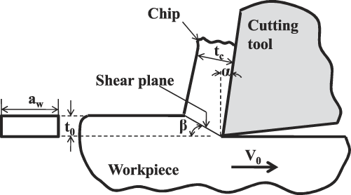
Machining has been used in recent years as an SPD process. In a typical machining process (Fig. 1), a wedge-shaped tool is fed orthogonally against a stationary workpiece at a low cutting speed (V 0). This ensures both low-temperature condition at the tool–chip interface region and condition of plane-strain. Intense plastic deformation on the shear plane oriented at an angle (β) with the surface of the workpiece results in a shaving (or chip) that possesses an ultrafine grain structure. The tool in orthogonal cutting has only two elements of geometry: (1) rake angle (α) which determines the direction of chip flow as it is formed and (2) clearance angle which provides a small clearance between tool flank and newly generated machined surface. During machining, the cutting edge of the tool is positioned at a certain distance below the original work surface. This corresponds to the undeformed chip thickness (t 0). As the chip is formed along the shear plane, its thickness increases to t c. The ratio of t 0 to t c is called chip thickness ratio (r c) and is usually less than 1. A state of plane strain (2D) deformation prevails when the tool edge is perpendicular to the cutting velocity (V 0) and the undeformed chip width (a w) is large compared to the undeformed chip thickness (t 0). The geometry of the deformation zone is completely determined by the shear plane angle (β) and the rake angle (α). Uniform shear strain (γ) imposed during deformation is calculated from the following equation Reference Shaw21
 $$\gamma = {{\cos \alpha } \over {\sin \beta \cos \left( {\beta - \alpha } \right)}}\;{\rm{where}}\;\tan {\rm{\beta }} = {{\left( {{t_0}/{t_{\rm{c}}}} \right)\cos {\rm{\alpha }}} \over {1 - \left( {{t_0}/{t_{\rm{c}}}} \right)\sin {\rm{\alpha }}}}{\rm{\quad.}}$$
Schematic of a typical machining process. V 0 is the cutting velocity, a w is the undeformed chip width, t 0 is the undeformed chip thickness, t c is the chip thickness, β is the shear plane angle, and α is the rake angle. Reference Swaminathan, Ravi Shankar, Lee, Hwang, King, Kezara, Rao, Brown, Chandrasekar, Compton and Trumble18

During the machining process, shear strains ranging between 1 and 10 can be imposed in a single pass of the tool. Reference Swaminathan, Ravi Shankar, Lee, Hwang, King, Kezara, Rao, Brown, Chandrasekar, Compton and Trumble18 The unconstrained nature of the machining process also enables the creation of nanocrystalline materials with enhanced hardness values from a wide range of metals and alloys. Reference Swaminathan, Ravi Shankar, Lee, Hwang, King, Kezara, Rao, Brown, Chandrasekar, Compton and Trumble18 Hence, it is a big source of nanostructured shavings with enhanced properties which can be upcycled as advanced materials. Machining is also economical vis-à-vis traditional SPD processes.
Precipitation heat treatable aluminum alloys like Al6061-T6 are widely used in aerospace and automotive sectors because of their high strength to weight ratio. The presence of the second-phase particles (precipitates) has been observed to accelerate grain refinement during the plastic deformation. Reference Shankar, Chandrasekar, Compton and King22 Shankar et al. Reference Shankar, Chandrasekar, Compton and King22 have utilized this grain refinement with precipitation to obtain nanostructured Al6061-T6 by machining. Swaminathan et al. Reference Swaminathan, Ravi Shankar, Rao, Compton, Chandrasekar, King and Trumble19 observed that the shear strain in the Al6061-T6 chip varies between 1.7 (for +20° rake tool) and 5.2 (−20° rake tool). With the change in imposed shear strain, the microstructure of the resulting chips changes from an elongated structure to equiaxed grains. This paper presents methods to produce straight chips from machining as an SPD process. Tensile test specimens fabricated from these straight chips are used to test their mechanical properties.
II. MACHINING AS SEVERE PLASTIC DEFORMATION
A. Experimental setup and preliminary tests
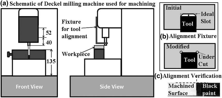
Large-strain cutting operations under plane-strain conditions were performed on a Deckel CNC milling machine. Schematic of this setup is presented in Fig. 2(a). The cutting tool is made of high speed steel (HSS) with a rake angle of 5°, since this falls between the extremes of positive and negative rakes. A portion of the tool was designed with circular cross-section to facilitate mounting on the CNC milling machine. The tool with the collet was inserted into the spindle, whose rotary motion was constrained. Cutting edge of the tool must be perpendicular to the cutting velocity to ensure machining under plane strain conditions. A fixture attached to the milling machine (Fig. 2) was used to align the cutting edge of the tool perpendicular to the cutting velocity. The fixture was removed after aligning the tool in proper position and prior to the machining operation. Figure 2(b) shows the top view of the fixture and tool with the dotted line indicating an ideal slot. Initially, while fabricating the slot in the fixture, a fillet of small radius was inevitably created making it difficult to align the tool. An undercut introduced in the slot facilitated the alignment as three surfaces of the tool match with those of the slot perfectly. To verify the tool alignment, a layer of black colored oil paint was smeared on the uncut workpiece surface which was then machined. The machining process was abruptly stopped and image of the workpiece surface [Fig. 2(c)] was taken. The angle between the workpiece axis and the border line between the cut portion (without paint) and the uncut portion (with paint) was measured using image processing software and was found to be 90° ± 0.2° This confirms machining under orthogonal conditions.
(a) Schematic of the Deckel milling machine. (b) Top view of the slot in alignment fixture with tool, where dashed line represents the desired slot: initial slot with a fillet at the corner and modified slot with an undercut at the corner. (c) Verification of tool alignment by machining the painted surface.

Rectangular plates (100 × 50 × 3 mm) of solution-treated Al6061-T6 were machined to create nanostructured chips. They were solution treated at 550° C for 10 h prior to the machining operation. Orthogonal machining tests were carried out with 0.3 mm depth of cut at a low cutting speed of 517 mm/min. Shavings or chips obtained had thickness of 1.38 ± 0.08 mm (mean ± standard deviation). Using Eq. (1), applied strain is estimated to be 4.68 ± 0.26. To obtain scratch-free specimens for measuring hardness, chips were polished successively with finer abrasive materials including the final 0.1 μm microid diamond compound with aerosol spray. The production of longer chips entailed use of longer rectangular plates (150 mm). The following precautions were necessary to obtain consistent reproducible results:
-
(i) Preliminary passes of machining have been performed to make workpiece surface perfectly flat relative to tool, failing which it can lead to side curl or discontinuous chips. After each test, material layer of ≈0.1 mm depth has been removed to prepare the surface for the next test.
-
(ii) After heat treatment, the workpiece was taken out of the furnace and rapidly quenched into water. During quenching, care should be taken to prevent the bending of plate. Otherwise, chips might flow out of plane while machining. The following cases were observed during quenching: (1) bending is more if the shorter edge of the plate touches the water first; (2) bending is negligible when the plate is kept parallel to the water surface, but it is difficult to ensure within a short span of time after taking the plate out of furnace; (3) bending is negligible when the longer edge of the plate is immersed in water first. The last procedure has been adopted as it is easy in practice and bending is less.
-
(iii) Workpiece has to be aligned such that it is exactly at the middle of tool cutting edge to avoid rotation of tool cutting edge by a very small angle.
B. Methods to produce straight chips
Attempts were made to procure chips with minimum curvature or straight chips so that dog-bone specimens could be prepared for measuring their tensile strength. To produce chips with minimum curvature, it is necessary to understand the mechanism of chip curl. Available literature on the reasons for chip curl indicate that the chip curl mechanism is related to the two zones of deformation in orthogonal cutting. These are described as the primary deformation zone in which the chip is formed and the secondary deformation zone in which there is severe deformation of the chip material due to large frictional forces between the chip and the rake face of the tool. Furthermore, at the tool–chip interface, there exist two zones which exhibit different frictional characteristics: sticking zone and sliding zone. Reference Worthington and Redford23 Sizes of these zones and the contact length could have a bearing on the curvature of the chips.
1. Machining with restricted contact tool
Jawahir Reference Jawahir24 presented the impact of restricting tool contact on breaking chips effectively and found that there is a possibility of obtaining straight chips during machining in some cases. For a range of materials machined orthogonally, Worthington and Redford Reference Worthington and Redford23 have provided experimental evidence that chips are formed with minimum curvature when the zone of sticking friction is equal in length to that of the restricted contact. Jawahir Reference Jawahir24 also showed that within the range investigated, sticking length varies linearly with chip thickness.
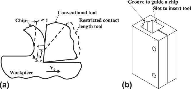
Restricted contact machining process has been used to produce straight chips. Figure 3(a) shows the machining operation under restricted contact condition between the tool and chip. Here, h is the restricted contact length; h n is the natural contact length; V 0 is the cutting velocity; and α is the primary rake angle. Rectangular plates of Al6061-T6 (150 × 50 × 3 mm) were solution treated before machining. The 5° rake angle tools with restricted contact lengths of 0.6 mm and 0.8 mm have been used for cutting. They resulted in the production of chips with minimum curvature which were suitable for preparation of tensile test specimens. The depth of cut and cutting speed are similar to those used for preliminary tests with the conventional tool.
(a) Schematic to depict machining with restricted contact tool and tool geometry. h is the restricted contact length, h n is the natural contact length, V 0 is the cutting velocity, and α is the primary rake angle. Reference Jawahir24 (b) Fixture for implementing extrusion-machining.

2. Extrusion-machining
A constrained chip formation process like the large-strain extrusion-machining (LSEM) can be used to produce geometrically defined bulk forms (e.g., sheet, foil, and wire) in contrast to the conventional machining process. Reference Saldana, Swaminathan, Brown, Moscoso, Mann, Compton and Chandrasekar25 LSEM process can be realized by using a suitable fixture with a cutting tool. A groove is made in the fixture to act as a constraint for the chip resulting from the machining process. A fixture has been fabricated from HSS with a groove for guiding the chip generated from the machining process [Fig. 3(b)]. The 1.5 mm deep groove was designed to procure a chip with thickness and width similar to that of the chip obtained by the unconstrained machining process (≈1.5 mm thick). This represents a combination of extrusion and machining processes. Extrusion-machining experiments have been carried out with the 5° rake angle tool under machining conditions similar to the preliminary tests. In this case as well, the curvature was reduced.
C. Chip morphology
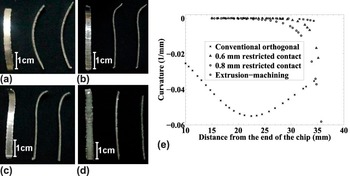
Representative chips obtained from different machining tests are shown in Figs. 4(a)–4(d). They clearly indicate the production of straighter chips using restricted-contact tools and extrusion-machining. To measure the curvature of chips obtained, the curved chip was traced and scanned. Co-ordinates of points on the curve were obtained using an image processing software and curvature at different points on chip were calculated using standard formulas.
Shavings obtained from (a) conventional orthogonal machining; (b) machining using tool with restricted contact length of 0.6 mm; (c) machining using tool with restricted contact length of 0.8 mm; (d) extrusion-machining. (e) Curvature variation along the length for the chips obtained from different machining processes.

Figure 4(e) shows variation of curvature along the chip length for the chips obtained from different machining processes. The curvature of chips obtained from machining with the restricted contact tool and extrusion-machining setup was minimal. The thicknesses of chips with minimum curvature are 1.07 ± 0.02 mm whereas those from conventional orthogonal machining operation are slightly higher, i.e., 1.38 ± 0.08 mm. Using Eq. (1), applied strain corresponding to these chips with minimum curvature is estimated to be 3.70 ± 0.05.
D. Metallography
Bulk material as well as chips was polished unto 0.1 μm for carrying out metallographic tests and etched with Keller's reagent 26 of composition: 2 mL HF, 3 mL HCL, 5 mL HNO3, and 190 mL water. Microstructure revealed by the etching process was observed at a magnification of 50x using an optical microscope. Grain sizes of solution-treated bulk Al6061 with and without peak-aging (Fig. 5) were 35.2 ± 7.1 μm and 33.3 ± 7.3 μm, respectively. Grain size change observed here is not significant which shows the effect of other factors like precipitation hardening in increasing the hardness of the heat-treated chips. The microstructure of chips obtained from various processes mentioned earlier (Fig. 6) clearly reveals flow lines which are characteristic of a continuous lamellar structure resulting from plastic shear. This is due to elongation of grains due to severe deformation in one direction in machining process.
Optical micrographs of bulk Al6061: (a) solution-treated; (b) peak-aged.

Optical micrographs of chips obtained from (a) machining using tool with restricted contact length of 0.6 mm; (b) machining using tool with restricted contact length of 0.8 mm; (c) extrusion-machining.

E. TEM analysis
Finer grain sizes in the shavings could not be measured by optical microscopy. Therefore, transmission electron microscopy (TEM) was used for that purpose. The samples were ground to a thickness of 100 μm using an abrasive polishing wheel, and 3 mm diameter disks were then punched out. They were made electron transparent by electrolytic twin-jet thinning at 18 V on Struers Tenupol polishing system using a mixture of 94% methanol and 6% perchloric acid as the electrolyte. To ensure the integrity of the microstructure of the chip, care was taken to avoid prolonged heating of the specimens during the mechanical thinning. Grain sizes were determined using line intercept method. If the aspect ratio of the grains (ratio of the length to width of a grain) was greater than 2, then the grain was considered as elongated; otherwise the grain was taken to be equiaxed. For the chips with elongated grain microstructures, the mean width of a grain is reported as the grain size. The chips obtained from solution-treated bulk Al6061 with and without heat treatment (Fig. 7) had grain sizes of 270 ± 48 nm and 165 ± 40 nm, respectively. Equiaxed grains were observed in case of heat-treated chips as compared with elongated grains observed in case of chips without heat treatment. Thus, grain refinement was observed from bulk material (33−35 μm) to chip.
TEM micrograph of (a) chip obtained from solution-treated Al6061; (b) heat-treated chip obtained from solution-treated Al6061.

III. MECHANICAL PROPERTIES OF CHIPS
A. Hardness tests
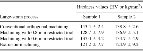
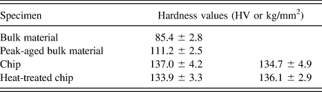
The chips obtained were polished unto 0.1 μm microid diamond compound with aerosol spray for performing microhardness tests on the samples. The results of the hardness tests on two specimens obtained from different large strain machining processes are presented in Table I. The hardness values of the straighter chips are less than those of chips obtained by the conventional orthogonal machining process. Moreover, the chips machined by using a tool of 0.6 mm restricted contact show less variation in their hardness values when compared to those obtained using both the 0.8 mm restricted contact tool and the extrusion-machining processes. The deviation in hardness values of the chips obtained from extrusion-machining might be because the groove made in the fixture does not allow the chip to flow freely. Furthermore, the resisting force offered by the groove might vary from one location to another during the flow of the chip. Thus, the chips obtained from machining with a tool of 0.6 mm restricted contact have been used to study the mechanical properties. Specimens made out of bulk material as well as chips were peak-aged/heat-treated at 175° for 8 h to study their effect on hardness and tensile properties. Table II shows the effect of peak-aging heat treatment on hardness values of bulk and chip material. Peak-aging on bulk material improved its hardness by about 30% and heat treatment of chip obtained from bulk material showed negligible effect on hardness values.
Results of microhardness tests for chips obtained from different machining processes using Vicker's indenter at 50 g load. 20 indentations were taken for each sample. Hardness of the bulk material was 85.4 ± 2.8 HV. Average values are reported along with standard deviation.

Results of microhardness tests for bulk material and chips obtained from 0.6 mm restricted contact machining process using Vicker's indenter at 50 g load. 20 indentations were taken for each sample. Both samples were tested before and after peak-aging in case of bulk material and heat treatment in case of chips to observe their effect on hardness. Average values are reported along with standard deviation.

B. Tensile testing
1. Preparation of small tensile test specimens
Chips with minimum curvature have been produced from the machining process using a tool with a restricted contact length of 0.6 mm. This resulted in hardness values with lower spread than those of chips obtained from other methods of producing straight chips. A nearly straight portion of the chip was cut from the raw chip to prepare a tensile test specimen. The raw chip has two surfaces, one of them being smoother than the other. The top surface of the chip is jagged since machining is an unconstrained deformation process. The bottom surface which slides on the tool face becomes smooth due to the friction between the tool and chip. Both the surfaces should be smooth for tensile test specimens so that there is no crack initiation due to surface defects. This can be achieved by polishing. Small size of the chip makes this polishing difficult. Special care has been taken while polishing the raw chips having small curvature. Hence, chips have been polished up to 0.4 mm thickness with a tolerance of 0.01 mm such that the rough portion is avoided.
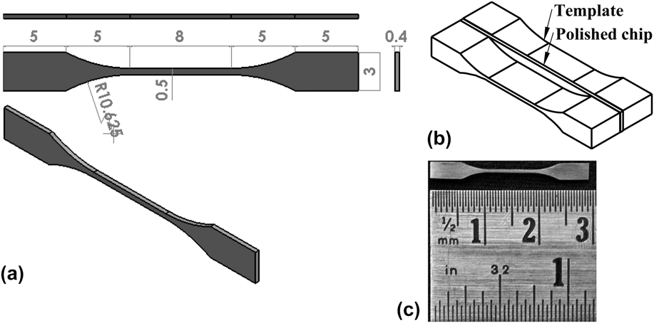
Fabrication of the tensile test specimens from polished chips is an intricate process. The small size of the chip limited the use of techniques such as electric discharge machining for fabrication of specimen. Hence, manual polishing was used to prepare test specimens. In this regard, steel templates have been prepared to match the dimensions of the tensile test specimen shown in Fig. 8(a). The straight portion of the chip (polished up to 0.4 mm thickness) has been placed between two properly aligned templates and clamped in machine vice [Fig. 8(b)]. Then the specimen was prepared to the required dimensions by filing and polishing it slowly with a tolerance limit of 0.01 mm throughout the gage length. During the preparation, dimensions of the specimen were checked frequently to keep variation of width within 0.01 mm throughout the gage length. A typical tensile test specimen is shown in Fig. 8(c). The detailed dimensions of the small tensile specimens prepared from the straight chips of nanocrystalline Al6061-T6 alloy are illustrated in Fig. 8(a).
(a) Dimensions of the small tensile test specimens (in mm). (b) Arrangement of steel templates and polished aluminum chip for specimen preparation. (c) Photograph of the final specimen.

For comparison, tensile test specimens have also been prepared from solution-treated Al6061 bulk material. Moreover, some specimens made from bulk solution-treated Al6061 and chips obtained from solution-treated Al6061 have been peak-aged/heat-treated prior to tensile tests to study their effect on tensile strength.
2. Tensile strength of bulk material and chips made from bulk material
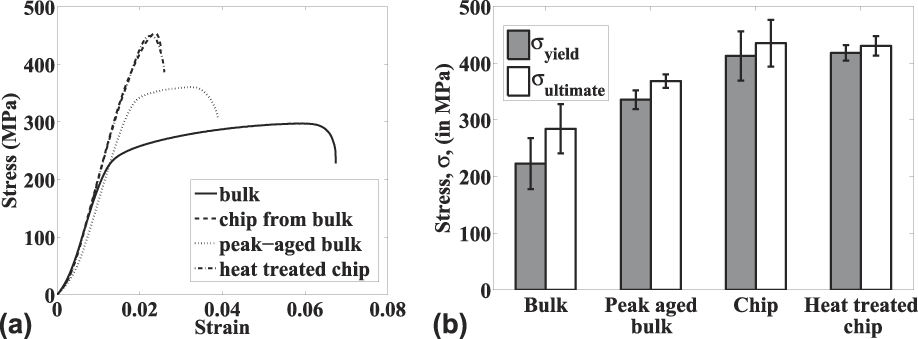
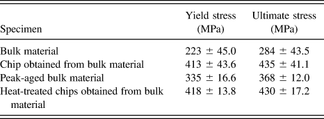
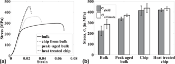
An INSTRON tensile testing machine has been used to conduct the tests on small tensile test specimens, at a moderate displacement rate of 0.96 mm/min. The chips obtained using the tool with restricted contact length of 0.6 mm were used in tensile tests since they show lesser variation in hardness values as discussed in the previous section. Typical tensile stress–strain curves for representative specimens made from bulk material and chips are shown in Fig. 9(a). Here, strains were estimated indirectly from the actuator displacement. The chips were found to have lower ductility when compared with that of the bulk material. Yield stress and ultimate tensile stress values for solution-treated Al6061 bulk, peak-aged Al6061 bulk, chips obtained from solution-treated Al6061, and heat-treated chips obtained from solution-treated Al6061 are presented in Table III and Fig. 9(b). To ensure repeatability, five specimens were prepared for each of the four conditions and subsequently tested. For each condition, Table III reports the average of five stress values along with the standard deviation. Following observations could be made from these results:
-
(i) The ultimate tensile strength and yield strength of the chips show about 53% and 85%, respectively, increase compared to those of the bulk material. These values are slightly higher than those obtained by Tham et al. Reference Tham, Fu, Hng, Pei and Lim10 using 8 pass ECAE.
-
(ii) Peak-aging treatment on the bulk material improves its tensile strength by 30% and yield strength by about 50%. But, heat-treated chips have nearly the same tensile strength and yield stress as that of chips without heat treatment.
(a) Tensile stress–strain curves for small specimens made of solution-treated Al6061: comparison between bulk material and chip with and without peak-aging / heat treatment; (b) yield stress and ultimate tensile stress values from tensile tests.

Yield stress and ultimate tensile stress values from tensile tests on small specimens. Bulk material is solution-treated Al6061. Five specimens were tested under each condition. Average values are reported along with standard deviation.

As discussed earlier, Kim et al. Reference Kim, Kim, Park and Kim12 have investigated post-aging behavior of equal channel angular-pressed Al6061, and it was found that post-aging treatment on nanostructured material improves ultimate tensile strength only by about 10%. Similar slight improvement in the tensile strength of heat-treated chips may not be visible here because of the 5% error in area of gage section and change in precipitation kinetics in deformed material (not taken into account during heat treatment). This possibility needs to be investigated further.
3. Young's modulus of small test specimens: size effect
In the stress–strain curves presented in Fig. 9(a), strains were estimated indirectly from the actuator displacement. Using these indirect measurements of strain values from actuator displacement, Young's moduli for all small specimens made from chips as well as bulk material were found to be in the range of 21–25 GPa. However, Young's modulus of specimens with larger dimensions (i.e., 5 mm × 5 mm, gage length = 40 mm) made from bulk material was found to be 68 ± 1 GPa. These large specimens were fabricated using bulk material from the same workpiece as was used for obtaining chips. The tensile strength for small specimens of solution-treated Al6061 bulk was observed to be the same as larger specimens while the failure strain was 50% less. These lower strain values and Young's modulus could be due to size effects. Stresses are estimated from load cell readings and measurement of gage cross-sectional dimensions before the experiments, both of which are accurate. However, the indirect method of estimating strain using actuator displacement was not satisfactory, and it was not possible to assert that the lower Young's modulus or failure strain thus obtained as mentioned above is accurate. To estimate strains and, consequently, Young's moduli more accurately, alternate methods of measuring strain in the gage section directly were explored.
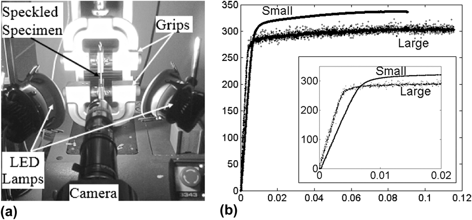
Digital image correlation (DIC) of speckles on the specimen was chosen to estimate the strain field in the gage section. Initially, specimens were spray painted with a thin layer of white paint and black speckles were introduced on to it. During the experiments, images of speckled specimens were acquired with a 1392 × 1040 pixels resolution CCD camera at 10 fps [Fig. 10(a)] with 3.5 ms exposure. They were correlated using software from Correlated Solutions to obtain full field strains and displacements. The load values acquired from the INSTRON machine were synchronized with the image acquisition. Input parameters for image correlation like subset size, filter size, step size etc. were varied and an optimum combination was used. Reference image was taken to be the image corresponding to 10 MPa rather than the zero load. Displacements in subsequent images were obtained relative to this image to avoid random orientations of displacement vectors at lower loads.
(a) Setup for acquiring images during experiment for DIC. (b) Tensile stress–strain curves for solution-treated Al6061: comparison between a larger specimen and a smaller specimen showing the effect of specimen size on material properties. Zoomed-in curve below 2% strain is shown in the inset.

Although the paint layer was kept as thin as possible while speckling, it might alter the strain measurements. Unpainted specimens when observed through the camera under appropriate lighting conditions were found to have a natural gray speckle pattern, perhaps due to reaction with the environment. Further, each speckle covers about 3 × 3 pixels in images taken by the camera, thus providing a good speckle pattern as suggested by Kammers and Daly. Reference Kammers and Daly28 These natural patterns were used for correlating the specimen images rather than introducing speckles by painting. However, the contrast in these speckles was low. These contrast-related problems were overcome by a combination of appropriate lighting, use of filter on the camera lens, and enhancement of contrast of the acquired image using a MATLAB code. Gage length on the specimen was marked with two lines using a black, permanent marker to identify them in the images. The area of interest was chosen between the marked lines, avoiding the edges, for the image correlation.
Average of the strains estimated at different locations on the gage section was taken and plotted against stress. Five tests were conducted for each condition (small samples: 0.4 × 0.4 mm and large samples: 6 × 2.5 mm). Figure 10(b) shows stress–strain curves for large and small solution-treated bulk specimens wherein strains were estimated by DIC. Young's moduli estimated from these tests were 50 ± 2 GPa for small specimens. They are much higher than 21–25 GPa estimated by indirect strain estimation using actuator displacement. This shows that indirect strain estimation using actuator displacement is inadequate. However, Young's moduli are still significantly lower than the corresponding values for larger specimens from the same workpiece (68 ± 1 GPa). Further research is under progress to understand this intriguing size effect.
Sergueeva et al. Reference Sergueeva, Zhou, Meacham and Branagan27 have studied the effect of gage length and sample size on measured mechanical properties of Ti–6Al–4V alloy sheet material during tensile testing. They have shown that the Young's modulus decreases with decrease in gage length and sample size, while the tensile strength remains constant. For reduced gage length of about 10 mm, Young's modulus was observed to be 40 GPa, nearly 64% below the value of bulk material specified in the literature. Similarly, in our studies, Young's modulus of small Al6061 specimens is 50 ± 2 GPa, about 26 ± 3% below the Young's modulus of specimens with larger gage sections. The reduction in Young's modulus of the smaller specimens than that of the larger specimens implies an increase in strain in the elastic region. But the plastic strain is lesser for smaller specimens compared with larger specimens which results in the failure of smaller specimens at lower strain values.
IV. CONCLUSIONS
UFG Al6061 alloy has been obtained using machining as a SPD process. The hardness of the chip obtained exceeds that of the bulk material indicating the impact of a finer grain structure on yield strength. In addition to higher hardness, the chips obtained from the conventional orthogonal machining tests have a large curvature. This research has demonstrated the possibility of obtaining chips with minimum curvature using restricted contact tool and the extrusion-machining processes. Flow lines typical of large strain deformation are seen in the continuous chips obtained in all the machining processes. Hardness of the straight chips obtained by the stated methods, though higher than that of the bulk material, is less than the hardness of curled chips obtained from conventional orthogonal machining. Furthermore, hardness of chips obtained using a tool with restricted contact length of 0.6 mm shows lesser variation. Therefore, a 0.6 mm restricted contact tool was used to create samples for the tensile tests.
From tensile tests, strength of Al6061 chips was found to be higher than solution-treated bulk Al6061 with 53% increase in ultimate strength and 85% increase in yield stress. The peak-aging heat treatment on bulk material resulted in 30% increase in ultimate strength and 50% increase in yield strength. In contrast, chips from solution-treated Al6061 show negligible change in strength after heat treatment. This shows that much better improvement in strength is obtained using machining as an SPD process as compared to peak-aging. The improvement in strength was accompanied by a reduction in ductility by 58% for chips obtained from solution-treated bulk material vis-à-vis bulk material. A novel method using DIC of natural speckles on specimens was used for direct measurement of longitudinal strains in these small samples wherein conventional strain measurement techniques are not very convenient. Young's moduli thus estimated for smaller specimens were 26 ± 3% lesser than those for larger specimens, indicating the influence of specimen size on Young's modulus. Plastic strains are also found to be lesser for smaller specimens. This effect of size of the specimen is being investigated further.
ACKNOWLEDGMENTS
The authors thank Frontier Life Line Pvt. Ltd., Chennai, for usage of tensile testing machine and the Manufacturing Engineering Section and Physical Metallurgy Laboratory at IIT Madras for providing experimental facilities. The authors also thank the materials and manufacturing panel of the Aeronautics Research & Development Board (ARDB) for their support.