1. Introduction
Multiphase flows are prevalent in both natural and engineering systems, where interactions between the dispersed and carrier phases give rise to a wide range of complex and nonlinear phenomena (Sippola et al. Reference Sippola, Kolehmainen, Ozel, Liu, Saarenrinne and Sundaresan2018; Carlotti & Maggi Reference Carlotti and Maggi2021; Brandt & Coletti Reference Brandt and Coletti2022; Zhang & Zhou Reference Zhang and Zhou2023; Garbin et al. Reference Garbin, Bothe, Brenn, Casciola, Colin, Marengo, Risso, Tryggvason and Lohse2025). In particular, the presence of dispersed phases – such as solid particles, liquid droplets or gas bubbles – can substantially alter the behaviour of wall-bounded turbulence (Balachandar & Eaton Reference Balachandar and Eaton2010; Russo et al. Reference Russo, Kuerten, van der Geld and Geurts2014; Mathai, Lohse & Sun Reference Mathai, Lohse and Sun2020; Bragg, Richter & Wang Reference Bragg, Richter and Wang2021). Depending on the physical properties and dynamic behaviour of the dispersed phase, such interactions may lead to either drag reduction or enhancement, making this topic of both fundamental interest and practical relevance (Lu, Fernández & Tryggvason Reference Lu, Fernández and Tryggvason2005; Zhang, Wang & Wan Reference Zhang, Wang and Wan2020; Kim et al. Reference Kim, Oshima, Park and Murai2021; Wang et al. Reference Wang, Yi, Jiang and Sun2022a ; Ni Reference Ni2024; Liao et al. Reference Liao, Lin, Liu, Liu and Lu2025). By elucidating how dispersed phases alter momentum transport and modulate drag, such insights not only contribute to improved energy efficiency but also provide a foundation for developing advanced flow control strategies in a wide range of industrial applications, including mixing, chemical processing and energy systems.
Among canonical configurations for studying multiphase wall turbulence, Taylor–Couette (TC) flow – characterised by fluid motion between two concentric rotating cylinders – offers a well-controlled environment for investigating the underlying physics (Taylor Reference Taylor1923; Eckhardt, Grossmann & Lohse Reference Eckhardt, Grossmann and Lohse2007; Huisman et al. Reference Huisman, Scharnowski, Cierpka, Kähler, Lohse and Sun2013; Grossmann, Lohse & Sun Reference Grossmann, Lohse and Sun2016; Blaauw, Lohse & Huisman Reference Blaauw, Lohse and Huisman2025). The interplay between centrifugal forces and viscosity in TC flow gives rise to rich dynamics, most notably the formation of Taylor vortices: large-scale, axisymmetric, counter-rotating structures that dominate angular momentum transport in the bulk flow (Ostilla et al. Reference Ostilla, Stevens, Grossmann, Verzicco and Lohse2013; Ostilla-Mónico et al. Reference Ostilla-Mónico, van der Poel, Verzicco, Grossmann and Lohse2014; Grossmann et al. Reference Grossmann, Lohse and Sun2016). These coherent structures play a central role in determining the global flow state, and any modulation of their stability or strength can significantly alter flow features such as the velocity profile, turbulence intensity and overall torque scaling.
Recent studies have shown that the introduction of a dispersed phase – such as particles or bubbles – into a TC system can modulate both the large-scale flow structure and the near-wall boundary layer, thereby affecting the angular momentum transport and flow regime transitions (Spandan et al. Reference Spandan, Ostilla-Mónico, Verzicco and Lohse2016b
; Dash, Anantharaman & Poelma Reference Dash, Anantharaman and Poelma2020; Baroudi et al. Reference Baroudi, Majji, Peluso and Morris2023). Among these, the drag modulation induced by buoyant bubbles has been particularly well studied. For instance, Murai, Oiwa & Takeda (Reference Murai, Oiwa and Takeda2005) demonstrated experimentally that adding a small volume fraction (1 %) of rising bubbles to a TC flow could reduce drag by up to 36 %. Building on these observations, Sugiyama, Calzavarini & Lohse (Reference Sugiyama, Calzavarini and Lohse2008) conducted direct numerical simulations using an Eulerian–Lagrangian framework and confirmed that drag reduction arises from the ability of bubbles to generate axial forces that suppress Taylor vortices. Subsequent studies extended this framework to higher Reynolds numbers and found that the Froude number (
 $\textit{Fr}$
), which characterises the relative strength of inertial to buoyant forces, plays a crucial role in controlling flow modulation (Spandan et al. Reference Spandan, Ostilla-Mónico, Verzicco and Lohse2016b
). At low
 $\textit{Fr}$
, strong buoyancy causes bubbles to rise rapidly, disrupting the coherent Taylor vortices and reducing drag. At high
 $\textit{Fr}$
, however, the buoyancy effect weakens and bubbles become trapped within the vortices, diminishing their influence on the flow. Beyond dispersed particles and bubbles, recent investigations have also demonstrated that polymer additives can significantly alter the flow dynamics and drag behaviour of TC turbulence. In particular, polymer-induced elasticity modifies the near-wall structures and suppresses large-scale vortical motions, leading to drag reduction (Lin et al. Reference Lin, Song, Liu, Liu, Lu and Khomami2024a
,
Reference Lin, Song, Liu, Wan, Lu and Khomamib
, Reference Lin, Song, Liao, Liu, Lu and Khomami2025; Zhang et al. Reference Zhang, Fan, Su, Xi and Sun2025). These studies highlight that, despite the very different physical mechanisms involved – buoyancy for bubbles and elasticity for polymers – the resulting modulation of angular momentum transport shares many similarities, making polymer-laden TC flow a highly relevant counterpart to particle-laden and bubbly TC systems.
In rotating flows such as TC flow, the radial motion of particles is primarily governed by the density ratio between the particles and the fluid (
 $\rho ^*$
). Particles with a density ratio less than unity (
 $\rho ^* \lt 1$
) experience centripetal forces that drive them inward (Chouippe et al. Reference Chouippe, Climent, Legendre and Gabillet2014; Bakhuis et al. Reference Bakhuis, Verschoof, Mathai, Huisman, Lohse and Sun2018), whereas particles with a density ratio greater than unity (
 $\rho ^* \gt 1$
) are subjected to centrifugal forces that propel them outward (Wereley & Lueptow Reference Wereley and Lueptow1999; Clarke & Davoodi Reference Clarke and Davoodi2025). This behaviour contrasts with that of bubbles, which, due to their significantly lower density, predominantly migrate inward under centripetal effects. In our prior work, we elucidated the mechanism underlying the radial distribution of particles in the TC system under conditions characterised by high density ratios (Jiang et al. Reference Jiang, Lu, Wang, Meng, Shen and Chong2025). That work identified three key mechanisms governing particle migration: centrifugal effects, biased sampling and turbophoresis. Among these, centrifugal effects consistently dominated, driving particles towards the outer wall, while biased sampling and turbophoresis played secondary but distinct roles depending on particle inertia. For neutrally buoyant particles, where the density ratio
 $\rho ^* \approx 1$
, the dynamics differs significantly as buoyancy and centrifugal effects become negligible. In TC flow, neutrally buoyant particles exhibit distinct behaviours depending on the Reynolds number. At low
 ${\textit{Re}}$
, neutrally buoyant particles undergo inertial migration that influences flow transitions – destabilising laminar states and stabilising vortex flows (Majji & Morris Reference Majji and Morris2018; Baroudi, Majji & Morris Reference Baroudi, Majji and Morris2020). At high
 ${\textit{Re}}$
, neutrally buoyant particles generally increase drag, with the extent of modification strongly affected by their shape and radial distribution, particularly near-wall clustering (Assen et al. Reference Assen, Ng, Will, Stevens, Lohse and Verzicco2022; Wang et al. Reference Wang, Yi, Jiang and Sun2022b
).
While the effect of buoyant bubbles has been relatively well explored, the role of inertial particles – especially under the influence of gravitational settling – remains less well understood in the context of TC flow. Several studies have highlighted the importance of particle inertia in drag modulation in wall-bounded turbulence (Costa, Brandt & Picano Reference Costa, Brandt and Picano2021; Wang, Xu & Zhao Reference Wang, Xu and Zhao2021; Gao, Wang & Parsani Reference Gao, Wang and Parsani2024), demonstrating that particles can alter turbulence production, energy dissipation and near-wall dynamics depending on their Stokes number. However, how the interplay between particle inertia and effective gravity (characterised by the Froude number) influences the global and local transport properties in TC systems is still an open question.
Addressing this knowledge gap is crucial for advancing our understanding of particle-laden wall turbulence and for designing efficient particle-based strategies for flow control. In this study, we investigate the combined effects of particle Stokes number (
 $\textit{St}$
) and Froude number (
 $\textit{Fr}$
) on drag modulation in turbulent TC flow using a two-way coupled Eulerian–Lagrangian approach. Our results reveal a non-trivial, non-monotonic relationship between drag and particle properties, and offer new insights into the mechanisms underlying structural transitions in particle-laden TC turbulence.
The remainder of the article is organised as follows. In § 2, we introduce the governing equations and numerical set-up. In § 3, we examine how the angular velocity flux and drag are modulated by settling particles, with a particular focus on their dependence on the particle Stokes number and Froude number. In § 4, we decompose the flux contributions into advection, viscous diffusion and particle-induced components to elucidate the mechanisms by which settling particles modulate drag in TC flow. In § 5, we investigate the modulation of flow structures by settling particles and demonstrate that particle addition suppresses the Taylor vortices. For heavy particles with sufficiently strong settling effects, we identify a transition to a regime of particle-induced turbulence. In § 6, we examine how the near-wall flow properties are influenced by the presence of particles. Finally, we provide a conclusion and outlook in § 7.
2. Governing equations and numerical set-ups
The TC system consists of a viscous fluid confined in the gap between two coaxially rotating cylinders. The inner and outer cylinders rotate with angular velocities
 $\omega _i$
and
 $\omega _o$
, respectively. Parameters
 $r_i$
and
 $r_o$
represent the radii of the inner and outer cylinders, respectively. The gap width between the two cylinders is denoted as
 $d=r_o-r_i$
. The geometric control parameters of the TC system include aspect ratio
 $\varGamma = L/d$
and the gap ratio
 $\eta = r_i / r_o$
, where
 $L$
is the height of the TC system. In this study, the outer cylinder is fixed, and the inner cylinder rotates with a constant angular velocity
 $\omega _i$
.
The Euler–Lagrangian framework is used to investigate the inertial particles settling in turbulent TC flow. The fluid phase is described by the incompressible Navier–Stokes equations, while the particle phase is described by the dispersed point-particle. The coupling between the fluid and particle phases is achieved through the hydrodynamic force acting on the particles. The dimensionless governing equations for the fluid phase are the incompressible Navier–Stokes equations, given by
 \begin{align} \displaystyle {\boldsymbol{\nabla }\boldsymbol{\cdot }\boldsymbol{u}=0,} \\[-28pt] \nonumber \end{align}
 \begin{align} \displaystyle {\frac {\partial \boldsymbol{u}}{\partial t} + (\boldsymbol{u} \boldsymbol{\cdot }\boldsymbol{\nabla }) \boldsymbol{u}=-\boldsymbol{\nabla }p+\frac {1}{{\textit{Re}}_i} {\nabla} ^{2} \boldsymbol{u} + \boldsymbol{f}_{\kern-2.5pt p},} \\[-28pt] \nonumber \end{align}
 \begin{align} \displaystyle {\boldsymbol{f}_{\kern-2.5pt p} = -\frac {\rho _p}{\rho _f} V_p \sum _{j=1}^{N_p}\left(\frac {{\rm d}\boldsymbol{v}}{{\rm d}t}-\frac {1}{\textit{Fr}^2}\boldsymbol{e}_z \right)\delta (\boldsymbol{x}-\boldsymbol{y}_{\!j}),}\\[6pt] \nonumber \end{align}
where
 ${\textit{Re}}_i = r_i \omega _i d/\nu$
is the Reynolds number based on the inner cylinder rotation,
 $\boldsymbol{u}$
and
 $\boldsymbol{v}$
represent the fluid and particle velocities, respectively,
 $\boldsymbol{f}_{\kern-1.5pt p}$
denotes the feedback force exerted by particles per unit mass of the fluid phase,
 $\rho _p$
and
 $\rho _f$
represent the particle and fluid densities, respectively,
 $V_{\!p}$
is the particle volume,
 $N_{\!p}$
is the number of particles,
 $\textit{Fr} = \omega _i \sqrt {r_i/g}$
is the Froude number,
 $\boldsymbol{e}_z$
is the unit vector in the axial direction and
 $\boldsymbol{y}_j$
denotes the instantaneous position of the
 $j$
th particle. The particle feedback force on the fluid is given by (2.3), where
 $\delta$
is the Dirac delta function and
 ${\rm d}\boldsymbol{v}/{\rm d}t$
is the acceleration of the particles. Equations (2.1)–(2.3) are normalised by the inner cylinder rotation velocity
 $r_i \omega _i$
and gap width
 $d$
.
The particles dispersed in the fluid phase are tracked using a Lagrangian point-particle approach with the Stokes drag, added mass, Saffman–Mei lift, buoyancy and gravity force (Gatignol Reference Gatignol1983; Maxey & Riley Reference Maxey and Riley1983; Maxey Reference Maxey1987; Tsai Reference Tsai2022). The momentum equation for the particle phase is given by
 \begin{align} \rho _p V_p \frac {{\rm d}\boldsymbol{v}}{{\rm d}t} &= \rho _p V_p \boldsymbol{g} - C_D \frac {\pi d_p^2}{8} (\boldsymbol{v} - \boldsymbol{u}) |\boldsymbol{v} - \boldsymbol{u}| + \rho _f V_p C_M \left ( \frac {{\rm D}\boldsymbol{u}}{{\rm D}t} - \frac {{\rm D}\boldsymbol{v}}{{\rm D}t} \right )\notag \\ &\quad + \rho _f V_p \left ( \frac {{\rm D}\boldsymbol{u}}{{\rm D}t} - \boldsymbol{g} \right ) - C_L \rho _f V_p (\boldsymbol{v} - \boldsymbol{u}) \times \boldsymbol{\omega }, \end{align}
where the terms on the right-hand side represent the gravitational force, Stokes drag force, added mass force, pressure gradient force and lift force, respectively. The particle density is denoted as
 $\rho _p$
,
 $V_p = \pi d_p^3/6$
is the particle volume,
 $d_p$
denotes the particle diameter,
 $\boldsymbol{u}$
and
 $\boldsymbol{\omega }$
are the velocity and vorticity of the fluid at the particle position, respectively,
 $\boldsymbol{v}$
is the particle velocity,
 $\boldsymbol{g}$
is the gravitational acceleration, while
 $C_D$
,
 $C_M$
and
 $C_L$
represent the drag, added mass and lift coefficients, respectively. Using the characteristic velocity
 $r_i \omega _i$
, characteristic length
 $r_i$
and fluid density
 $\rho _f$
, (2.4) can be normalised and simplified as
 \begin{eqnarray} \frac {{\rm d}\boldsymbol{v}}{{\rm d}t} = \frac {C_D}{\textit{St}}(\boldsymbol{u}-\boldsymbol{v}) + (\beta +1)\frac {{\rm D}\boldsymbol{u}}{{\rm D}t} + \frac {\beta +1}{3}\ (\boldsymbol{u}-\boldsymbol{v}) \times \boldsymbol{\omega }+ \beta \frac {1}{\textit{Fr}^2}\boldsymbol{e}_z. \end{eqnarray}
Here,
 $\textit{St} = {d_p^*}^2 {\textit{Re}}_i / 12 (\beta +1)$
represents the particle Stokes number based on the inner cylinder rotation speed and
 $\beta = 2 (1-\rho ^*)/(1+2\rho ^*)$
is a parameter related to density ratio
 $\rho ^*$
. For the drag coefficient, the Shiller–Naumann relation
 $C_D = 1+0.15{\textit{Re}}_p^{0.687}$
is used, which is valid for particle Reynolds number
 ${\textit{Re}}_p = d_p|\boldsymbol{v}-\boldsymbol{u}|/\nu$
up to 1000 (Naumann & Schiller Reference Naumann and Schiller1935). The added mass coefficient is set to
 $C_M = 0.5$
and the lift coefficient is set to
 $C_L = 0.5$
(Spandan et al. Reference Spandan, Ostilla-Mónico, Verzicco and Lohse2016b
; Sugiyama et al. Reference Sugiyama, Calzavarini and Lohse2008).
Direct numerical simulations of the carrier phase are performed using a second-order-accurate finite-difference method in cylindrical coordinates
 $( \boldsymbol{e}_r, \boldsymbol{e}_{\theta }, \boldsymbol{e}_z)$
. The governing equations are numerically solved by using a fraction third-order Runge–Kutta scheme (Verzicco & Orlandi Reference Verzicco and Orlandi1996; Ostilla et al. Reference Ostilla, Stevens, Grossmann, Verzicco and Lohse2013; Song, Shishkina & Zhu Reference Song, Shishkina and Zhu2024). The time step is chosen so as not to exceed the the Courant–Friedrichs–Lewy condition and particle relaxation time. A uniform grid is employed in the azimuthal and axial directions with grid spacing
 $r_i^+\Delta \theta = r_i\Delta \theta /\delta _{\nu ,i} = 6.64$
and
 $\Delta z^+ = \Delta z/\delta _{\nu ,i} = 4.22$
, and a non-uniform grid spacing using a clipped Chebyshev-type clustering method in the radial direction with
 $\Delta r^+ = \Delta r/\delta _{\nu ,i}$
ranging from 0.17 to 1.29 (single-phase inner viscous length scale
 $\delta _{\nu ,i} = \nu / u_{\tau ,i}$
; Huisman et al. Reference Huisman, Scharnowski, Cierpka, Kähler, Lohse and Sun2013). We ensure 2–3 grid points within the viscous sublayer
 $(y^+\lt 1)$
. The velocity profiles normalised by the friction velocity can be found in § 1 of the supplementary material available at https://doi.org/10.1017/jfm.2025.10850. As a result, the numbers of grid points in the
 $\theta$
,
 $r$
and
 $z$
directions are
 $N_{\theta }=150$
,
 $N_r = 200$
and
 $N_z = 180$
, respectively.
To reduce computational cost, we exploit a rotational symmetry of
 $n_{sym}=6$
, meaning that the computational domain spans only
 $1/6$
of the full azimuthal direction. The aspect ratio is set to
 $\varGamma =L/d=4$
and radius ratio
 $\eta =0.833$
. These parameters have been validated for simulation accuracy of two-phase TC flow in Spandan et al. (Reference Spandan, Ostilla-Mónico, Verzicco and Lohse2016b
). The no-slip boundary condition is applied at the inner and outer cylinder walls, and the periodic boundary condition is applied in the azimuthal and axial directions for the carrier phase and dispersed phase. The complete elastic collisions have been used to calculate the particle–wall collisions. The fluid information at the particle location and the feedback force (2.3) extrapolated from the particle location to grid nodes are both calculated by a tri-linear scheme. In order to be consistent with Sugiyama et al. (Reference Sugiyama, Calzavarini and Lohse2008) and Spandan et al. (Reference Spandan, Ostilla-Mónico, Verzicco and Lohse2016b
), we also fix the mean axial flow flux to be zero at each
 $z$
position. In this study, the particle volume fraction is fixed at
 $6 \times 10^{-5}$
, allowing particle–particle interactions to be neglected, while the Reynolds number of the carrier phase is maintained at
 ${\textit{Re}}_i = 3500$
. The particle Stokes numbers
 $\textit{St}$
range from 0.088 to 0.876, and the Froude number
 $\textit{Fr}$
varies from 0.16 to 2.56. For comparison, the cases with
 $\textit{Fr}^{-1} = 0$
are also considered, where the gravitational effects are neglected. For convenience,
 $\textit{Fr}^{-1}$
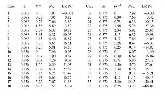
will be used to represent the magnitude of the effective gravity in the following sections. The details of the particle parameters are summarised in table 1.
Details of the settling particle parameters and results for the numerical simulations. Density ratio
 $\rho ^* = \rho _p/\rho _f$
, defined as the ratio of particle to fluid density, is varied in the range
 $50 \leqslant \rho ^* \leqslant 500$
. Stokes number
 $\textit{St} = {d_p^*}^2 {\textit{Re}}_i / 12 (\beta +1)$
is the particle bulk Stokes number. For all cases, the dimensionless particle diameter
 $d_p^* = d_p / d$
and volume fraction
 $\phi _v = N_p V_p/V_f$
are fixed at 0.003 and
 $6 \times 10^{-5}$
, respectively. The particle mass loading ratio
 $\phi _m = N_pm_p/m_f$
ranges from
 $3.1\times 10^{-3}$
to
 $3.1\times 10^{-2}$
. For the case of
 $\textit{Fr}^{-1} = 0$
, the gravitational effects can be neglected. For the single phase, the dimensionless angular velocity flux
 $\textit{Nu}_{\omega }=7.96$
, which differs from the result of Spandan et al. (Reference Spandan, Ostilla-Mónico, Verzicco and Lohse2016b
) by about 1.4 %.

3. Angular velocity flux and drag modulation
In TC flow, the torque needed to drive the cylinders
 $T$
and the angular velocity flux
 $J^{\omega }$
are related by
 $T = 2\pi L \rho J^{\omega }$
(Eckhardt et al. Reference Eckhardt, Grossmann and Lohse2007), and
 $J^{\omega }$
is conserved in the radial direction. The definition of
 $J^{\omega }$
is given in § 4. Parameter
 $\textit{Nu}_{\omega }$
represents the dimensionless angular velocity flux, where it is defined by
 $\textit{Nu}_{\omega }=J^{\omega }/J_{\textit{lam}}$
with normalisation by the flux in laminar flow
 $J_{\textit{lam}}=2\nu r_i^2\ r_o^2\ \omega _i/(r_o^2-r_i^2)$
. The net percentage drag reduction can be defined as follows (Spandan et al. Reference Spandan, Ostilla-Mónico, Verzicco and Lohse2016b
):
 \begin{gather} {\rm DR}=\frac {\left \langle \textit{Nu}_\omega \right \rangle _s-\left \langle \textit{Nu}_\omega \right \rangle _t}{\left \langle \textit{Nu}_\omega \right \rangle _s} \times 100\,\%=\frac {\big \langle C_f\big \rangle _s-\big \langle C_f\big \rangle _t}{\big \langle C_f\big \rangle _s} \times 100\,\%, \end{gather}
where
 $\left \langle \cdots \right \rangle _s$
and
 $\left \langle \cdots \right \rangle _t$
correspond to averaging for single-phase and two-phase systems, respectively, and
 $C_f = 2\tau _{w}/\rho u_{\theta ,i}^2$
represents the friction factor, where
 $\tau _{w}$
and
 $u_{t,i}$
are the averaged wall shear stress and inner cylinder rotation velocity, respectively.
(
 $a$
) Nusselt number
 $\textit{Nu}_{\omega }$
for two-phase TC flows under varying particle Stokes numbers (
 $\textit{St}$
) and inverse Froude numbers (
 $\textit{Fr}^{-1}$
), compared with single-phase (SP) flow (horizontal dashed line) at
 ${\textit{Re}}_i = 3500$
. (
 $b$
) The net percentage drag reduction (DR) for the two-phase TC flows, illustrating the influence of particle
 $\textit{St}$
and
 $\textit{Fr}^{-1}$
.

We first present results for the influence of the settling particles on the drag reduction in TC flow. Nusselt number
 $\textit{Nu}_\omega$
for two-phase TC flows is presented in figure 1(a), illustrating the influence of particle Stokes numbers (
 $\textit{St}$
) and inverse Froude numbers (
 $\textit{Fr}^{-1}$
) on the flow angular velocity transport and the corresponding drag reduction in figure 1(b). Here,
 $\textit{Nu}_\omega$
is obtained after statistical stationarity is reached, by averaging over at least 40 full cylinder rotations, using no fewer than
 $2.5\times 10^{4}$
snapshots, the same for all subsequent turbulent statistics. With varying strength of particle gravitational settling,
 $\textit{Nu}_\omega$
exhibits non-monotonic variation. As
 $\textit{Fr}^{-1}$
increases, there is more than 20 % drag reduction, where the amount of drag reduction reaches a maximum value at certain optimal
 $\textit{Fr}^{-1}$
. For heavy particles (
 $\textit{St} = 0.375, 0.876$
),
 $\textit{Nu}_{\omega }$
increases markedly after the optimal point leading to drag enhancement in the TC flow for large
 $\textit{Fr}^{-1}$
limit. The observed behaviour leads to the question as to what leads to the drag reduction and the subsequent enhancement in drag.
Dimensionless contributions of angular velocity flux for varying particle
 $\textit{St}$
and
 $\textit{Fr}^{-1}$
, compared with single-phase flow (dashed line). (
 $a$
,
 $b$
) The advection terms and viscous diffusion terms for
 $\textit{St} = 0.088$
; (
 $c$
,
 $d$
) the advection terms and viscous diffusion terms for
 $\textit{St} = 0.876$
.

4. Decomposition of flux contribution
To investigate the mechanism of drag modulation, we decompose the angular velocity flux into various parts. For the two-phase TC system, the angular velocity flux
 $J^{\omega }$
must also account for the feedback force from the particles. Following the approach proposed in Su et al. (Reference Su, Yi, Zhao, Wang, Xu, Wang and Sun2024), the angular velocity flux
 $J^{\omega }$
for two-phase TC flow can be decomposed into three parts where
 $J_A = r^3\langle u_r \omega \rangle _{\theta ,z,t}$
,
 $J_V = -r^3\nu \left \langle \partial _r \omega \right \rangle _{\theta ,z,t}$
and
 $J_P = -\int _{r_i}^{r} \langle r^2f_{\theta } \rangle _{\theta ,z,t}$
represent the contributions from the advection, viscous diffusion and particle feedback to the angular velocity flux, respectively. Here,
 $\left \langle \cdots \right \rangle _{\theta ,z,t}$
denotes averaging over time and in the
 $\theta ,z$
direction and
 $f_{\theta }$
represents the azimuthal components of (2.3).
The contributions of
 $J_A$
,
 $J_V$
normalised by the corresponding values can be obtained from the laminar flow
 $J_{\textit{lam}}$
in figure 2. Despite the addition of particles, the contribution of particle feedback term
 $J_P$
to the angular velocity flux remains below 1 % across all cases. Therefore, this term has been neglected in the subsequent analysis. In contrast, the advection term predominantly governs the bulk region, while viscous diffusion dominates within the boundary layers of the TC system, consistent with the findings of Brauckmann & Eckhardt (Reference Brauckmann and Eckhardt2013).
When particle settling is neglected (i.e.
 $\textit{Fr}^{-1}=0$
), the contributions to angular velocity flux exhibit minimal variation. For light particles (
 $\textit{St} = 0.088$
), the introduction of effective gravity leads to a reduction in both advective and viscous diffusion contributions within their respective dominant regions, consistent with the observed drag reduction. In contrast, for heavy particles (
 $\textit{St} = 0.876$
), these contributions initially decrease but subsequently increase with increasing effective gravity, eventually surpassing the single-phase values when
 $\textit{Fr}^{-1}\gt 3.13$
.
Dimensionless contributions of Taylor vortex and Reynolds stress as a function of radial position. (a) Taylor vortex contribution,
 $\textit{St}=0.088$
, (b) Reynolds stress contribution,
 $\textit{St}=0.088$
, (c) Taylor vortex contribution,
 $\textit{St}=0.876$
, (d) Reynolds stress contribution,
 $\textit{St}=0.876$
. The dashed lines present the single-phase case.

5. Modulation of flow structure by settling particles
Note that since TC turbulence consists of both turbulent Taylor vortices and background fluctuations, it is meaningful to decompose the advection contribution of flux
 $J_A = r^3\langle u_r \omega \rangle _{\theta ,z,t}$
into two components (Eckhardt et al. Reference Eckhardt, Grossmann and Lohse2007; Zhang et al. Reference Zhang, Fan, Su, Xi and Sun2025):
 \begin{gather} r^3\left \langle u_r \omega \right \rangle _{\theta ,z,t} = r^3\left \langle \left \langle u_r\right \rangle _{\theta ,t} \left \langle \omega \right \rangle _{\theta ,t} \right \rangle _{z}+ r^3\left \langle u_r^{\prime } \omega ^{\prime } \right \rangle _{\theta ,z,t}, \end{gather}
where
 $\langle \langle u_r\rangle _{\theta ,t} \langle \omega \rangle _{\theta ,t} \rangle _{z}$
and
 $\langle u_r^{\prime } \omega ^{\prime } \rangle _{\theta ,z,t}$
represent the contribution of the Taylor vortex and Reynolds stress to the angular velocity flux, respectively, where
 $u_r^{\prime } = u_r - \left \langle u_r \right \rangle _{\theta ,t}$
. Note that the Reynolds stress contribution is not identical to the Reynolds stress; see § 2 of the supplementary material for details. The dimensionless forms of Taylor vortex contribution
 $J_{\textit{T}V} = r^3\langle \langle u_r\rangle _{\theta ,t} \langle \omega \rangle _{\theta ,t} \rangle _z /J_{\textit{lam}}$
and Reynolds stress contribution
 $J_{RS} = r^3\langle u_r^{\prime }\omega ^{\prime } \rangle _{\theta ,z,t}/J_{\textit{lam}}$
are shown in figure 3. For the single-phase case,
 $J_{\textit{T}V}$
is larger than
 $J_{RS}$
, indicating that, under the present parameters, the angular velocity transport in the TC system is predominantly contributed by the Taylor vortices.
At
 $\textit{Fr}^{-1}=0$
, the addition of light particles exerts minimal influence on the overall angular velocity flux, due to a balance between two competing effects: the suppression of the Taylor vortex contribution
 $J_{\textit{T}V}$
and the simultaneous enhancement of flux from turbulent fluctuations
 $J_{RS}$
in the bulk region. This insensitivity differs notably from the case of heavy particles, which show only a weak influence on both
 $J_{\textit{T}V}$
and
 $J_{RS}$
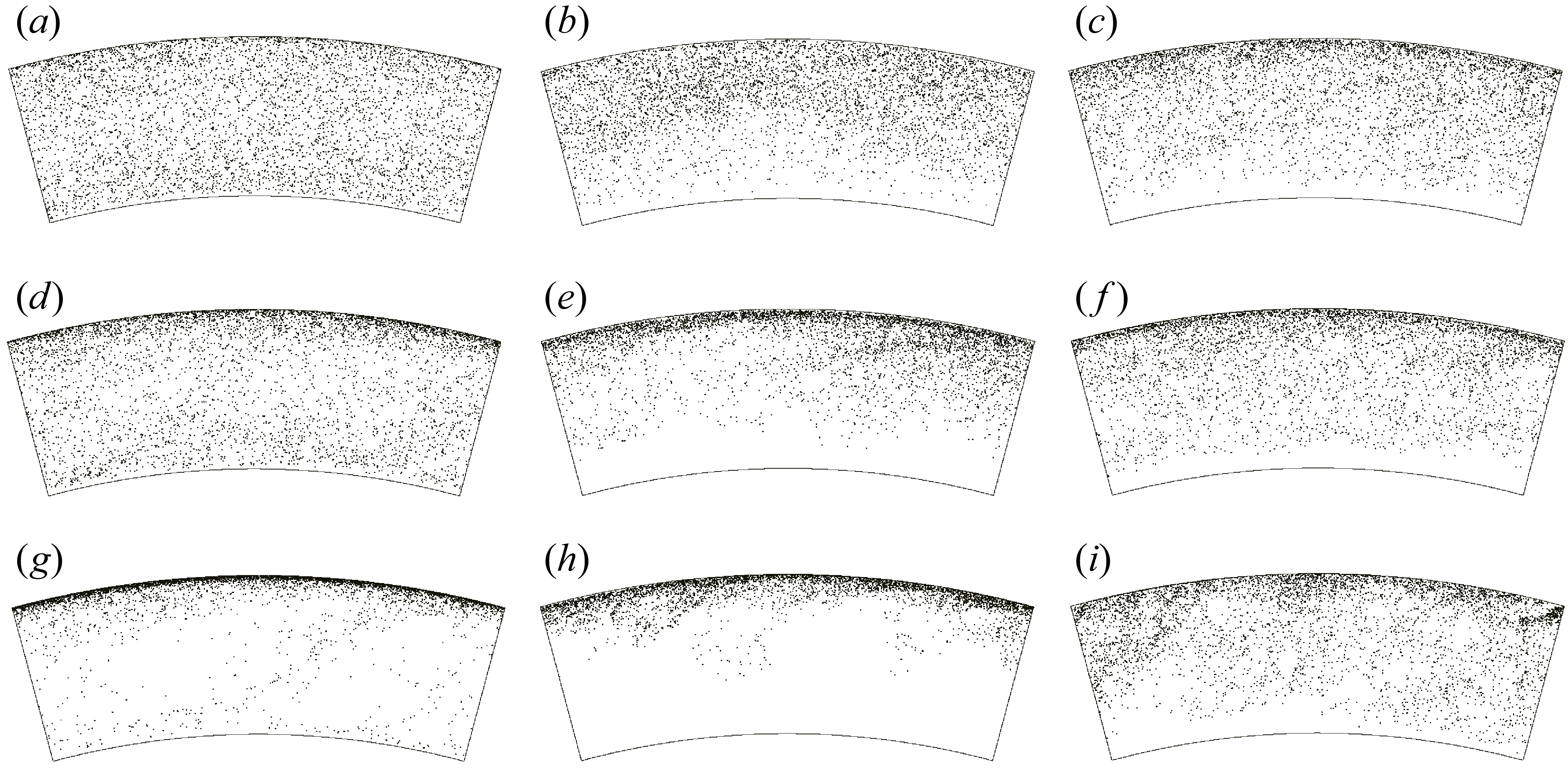
under the same conditions. The distinction arises from the differing spatial distributions and transport dynamics of the particles: light particles are more uniformly dispersed throughout the bulk and are passively carried by the flow, facilitating the transfer of angular momentum from the fluid to the particles (see figure 4). This interaction suppresses the coherence of mean Taylor vortices while amplifying the intensity of background fluctuations. In contrast, heavy particles experience strong centrifugal forces, causing them to accumulate near the outer cylinder wall and interact less with the bulk flow, thereby exerting limited influence on advective transport.
As the effect of gravitational settling increases (
 $\textit{Fr}^{-1}$
rises), the contribution from coherent Taylor vortices progressively diminishes, becoming minimal in the case of heavy particles. In contrast, the contribution from background turbulent fluctuations increases significantly with rising
 $\textit{Fr}^{-1}$
, indicating a transition towards a flow regime dominated by particle-induced turbulence. In this regime, particles are more likely to be transported from the outer-cylinder region towards the bulk under the action of strong turbulent fluctuations.
Top-view instantaneous snapshots of particle distribution for varying Stokes numbers
 $\textit{St} = 0.088$
(
 $a$
–
 $c$
),
 $\textit{St} = 0.176$
(
 $d$
–
 $f$
) and
 $\textit{St} = 0.876$
(
 $g$
–
 $i$
), and varying inverse Froude numbers
 $\textit{Fr}^{-1} = 0$
(
 $a$
,
 $d$
,
 $g$
),
 $\textit{Fr}^{-1} = 2.34$
(
 $b$
,
 $e$
,
 $h$
) and
 $\textit{Fr}^{-1} = 5.26$
(
 $c$
,
 $f$
,
 $i$
). Only the angular range
 $\theta \in (0,\pi /6)$
is shown.

The (
 $r$
–
 $z$
) plane angular velocity contours (left) and radial velocity contours (right) for varying
 $\textit{St}$
:
 $(a{-}c)$
 $\textit{St}=0.088$
,
 $(d{-}f)$
 $\textit{St}=0.176$
,
 $(g-i)$
 $\textit{St}=0.375$
and
 $(j{-}l)$
 $\textit{St}=0.876$
; and varying
 $\textit{Fr}^{-1}$
: (a,d,g, j)
 $\textit{Fr}^{-1}=0$
, (b,e,h,k)
 $\textit{Fr}^{-1}=0.78$
and (c,f,i,l)
 $\textit{Fr}^{-1}=5.26$
. Only the axial domain
 $z \in (0,2)$
is shown. In
 $(a)$
, the red box indicates the Taylor vortex region, while in
 $(d)$
, the green boxes mark the Görtler vortex regions generated around the plume due to centrifugal instability.

The (
 $r$
–
 $z$
) plane mean angular velocity contours.
 $(a)$
Single-phase case,
 $(b)$
 $\textit{St}=0.876,\ \textit{Fr}^{-1}= 0$
,
 $(c)$
 $\textit{St}=0.876,\ \textit{Fr}^{-1}= 0.78$
and
 $(d)$
 $\textit{St}=0.876,\ \textit{Fr}^{-1}= 5.26$
.

Viscous dissipation rate near the cylinder wall, normalised by the single-phase (SP) case
 $\epsilon /\epsilon _{s,i}$
, where
 $\epsilon _{s,i}$
represents the viscous dissipation rate of the single phase at the inner cylinder surface, for (
 $a{,}b$
)
 $\textit{St} = 0.088$
and (
 $c{,}d$
)
 $\textit{St} = 0.876$
. (a,c) The region near the inner cylinder and (b,d) the region near the outer cylinder.

The vanishing of the Taylor vortex contribution (
 $J_{\textit{T}V}$
) does not imply the complete absence of Taylor vortices in the TC system. When the vortices exhibit axial migration or strong temporal fluctuations, the averaging operation can cause
 $J_{\textit{T}V}$
to vanish despite the vortices still being present. To clarify the underlying flow states in the two-phase TC system, we present instantaneous snapshots of angular velocity and radial velocity in the radial–axial plane, as shown in figure 5. In the absence of settling effect, Taylor vortices are clearly visible in the bulk region, where they dominate the flow. At small values of
 $\textit{Fr}^{-1}$
, increasing particle inertia causes the edges of the Taylor vortices to become increasingly blurred, accompanied by axial oscillations. In this case, velocity plumes near the wall are primarily governed by small-scale Görtler vortices (Dong Reference Dong2007; Zhang et al. Reference Zhang, Fan, Su, Xi and Sun2025). At
 $\textit{St} = 0.176$
and
 $\textit{Fr}^{-1} = 0.78$
, Taylor rolls are still discernible in the instantaneous snapshots, although the contribution from
 $J_{\textit{T}V}$
has already diminished.
For heavy particles (
 $\textit{St} = 0.375, 0.876$
), even a small effective gravity disrupts the Taylor vortices, as shown in figure 5(
 $h\textrm{,}k$
), leading to rapid suppression of the mean Taylor vortex structures and a concurrent increase in background turbulent fluctuations. However, this enhancement of turbulence is weaker than the suppression of the vortex contribution, resulting in significant drag reduction in the system. The same phenomenon can also be observed in the time-averaged angular velocity field, as shown in figure 6. When gravity is taken into account, the time-averaged Taylor vortex structures also disappear. To further analyse this, we computed
 $\langle u_r\rangle _{\theta ,t}$
in accordance with (5.1), and found that when the mean Taylor vortex effect is present, the averaged
 $\langle u_r\rangle _{\theta ,t}$
field clearly exhibits the characteristic structure of Taylor vortices. In contrast, when the mean Taylor vortex contribution is negligible, the averaged
 $\langle u_r\rangle _{\theta ,t}$
field is nearly zero, indicating that the flow in the bulk region is predominantly governed by turbulent fluctuations, as shown in figure 5 for large
 $\textit{Fr}^{-1}$
.
Azimuthal velocity profile near the cylinder wall for (
 $a{,}b$
)
 $\textit{St} = 0.088$
and (
 $c{,}d$
)
 $\textit{St} = 0.876$
. (a,c) The region near the inner cylinder and (b,d) the region near the outer cylinder.

6. Near-wall properties modulated by particles
Next, we examine how changes in the flow structure lead to distinct near-wall properties, such as viscous dissipation rates. This analysis is essential, as drag reduction is typically associated with a decrease in viscous dissipation (Eckhardt et al. Reference Eckhardt, Grossmann and Lohse2007; Sugiyama et al. Reference Sugiyama, Calzavarini and Lohse2008; Spandan et al. Reference Spandan, Lohse and Verzicco2016a
). To understand how settling particles influence drag in the near-wall region, figure 7 presents the dissipation rate normalised by the single-phase dissipation at the inner cylinder
 $\epsilon /\epsilon _{s,i}$
, where
 \begin{gather} \epsilon =\frac {1}{2}\nu \sum _{\textit{ij}}\left(\frac {\partial u_j}{\partial x_i} + \frac {\partial u_i}{\partial x_j}\right)^2. \end{gather}
We compare the two-phase dissipation profiles for light particles (
 $\textit{St} = 0.088$
) and heavy particles (
 $\textit{St} = 0.876$
).
For light particles, the near-wall viscous dissipation is significantly reduced, except in the case of
 $\textit{Fr}^{-1}=6.25$
near the outer cylinder. However, in the outer part of the near-wall region, particle settling leads to enhanced viscous dissipation. In contrast, for heavy particles under the drag-enhanced cases, the near-wall dissipation is significantly elevated, with peak values reaching up to 30 times those of the single-phase system. To further assess how particles modulate the near-wall velocity field, we plot the azimuthal velocity profiles near the inner cylinder in figure 8. Light particles enhance the velocity near the inner cylinder wall while reducing it near the outer cylinder, leading to a smaller velocity gradient in the near-wall region. In contrast, under strong effective gravity, heavy particles cause a sharp drop in the near-wall azimuthal velocity. This sharp change in velocity implies that the near-wall velocity gradient can be significantly altered by the presence of settling particles, suggesting that particles can effectively modify the boundary-layer thickness.
Finally, we estimated the inner and outer velocity boundary-layer thickness from the azimuthal velocity (
 $u_{\theta }$
) profile, as shown in figure 9, following the method of Ostilla et al. (Reference Ostilla, Stevens, Grossmann, Verzicco and Lohse2013).To determine the boundary-layer thickness, we first obtain the boundary-layer slope by a fitting through the first three grid points near the wall. For the bulk, the slope is taken from a fitting around the inflection point, using two points on each side. The intersection of the respective boundary-layer line and bulk line defines the boundary-layer thickness. Our results reveal that the variation in boundary-layer thickness closely correlates with the observed drag reduction: an increase in boundary-layer thickness corresponds to reduced drag, while a thinner boundary layer is associated with increased drag. This trend suggests that particle-induced modifications to the near-wall shear and momentum transport play a key role in altering the boundary-layer dynamics. Specifically, a thinner boundary layer intensifies velocity gradients, which can increase turbulent momentum transport and lead to drag enhancement. Conversely, a thicker boundary layer may reflect a damping of near-wall turbulence and a weakening of Taylor vortices, thereby reducing the exchange of angular momentum and contributing to drag reduction.
These results indicate that particle settling modulates drag not only directly by altering the large-scale coherent structures in the bulk region, but also indirectly by influencing energy dissipation and the boundary-layer thickness near the inner cylinder wall – even in regions with relatively low particle number density.
Boundary-layer thickness normalised by the single-phase (SP) case. Here
 $\delta _{i}$
and
 $\delta _{o}$
represent inner and outer boundary-layer thickness, respectively. The subscript ‘
 $s$
’ denotes the single-phase case.
 $(a)$
Dimensionless inner boundary-layer thickness.
 $(b)$
Dimensionless outer boundary-layer thickness.

7. Conclusions and outlook
In summary, we have systematically studied how particle inertia and gravitational settling modulate drag in turbulent TC flow using a two-way coupled Eulerian–Lagrangian framework. By varying the Stokes number and Froude number, we revealed a non-monotonic behaviour in drag modulation. Light particles (small
 $\textit{St}$
) suppress coherent Taylor vortices and reduce drag, while heavy, fast-settling particles enhance turbulent transport and ultimately increase drag.
A key finding is that drag modulation arises not directly from the instantaneous momentum exchange between particles and fluid, but rather from particle-induced reorganisation of the flow topology. This reorganisation manifests as a competition between coherent Taylor vortices and turbulence driven by particle dynamics. Through decomposition of the angular velocity flux, we quantified the contributions from advection, viscous diffusion and Reynolds stress, thereby clarifying the mechanisms underlying the transition between drag-reducing and drag-enhancing regimes.
Further insight was gained by decomposing the advective flux into contributions from Taylor vortices and background turbulent fluctuations. At moderate particle inertia and gravitational settling (characterised by
 $\textit{Fr}^{-1}$
), particles weaken the coherence of Taylor vortices, thereby reducing angular velocity flux transport and leading to drag reduction. As gravitational settling becomes stronger, the flow undergoes a structural transition: rapidly settling particles disrupt the Taylor vortices and promote a shift from a vortex-dominated regime to one governed by particle-induced turbulence. This reorganisation of transport mechanisms leads to an increase angular velocity transfer efficiency and consequently to enhanced drag.
In addition to bulk flow transition, particle settling also strongly affects near-wall dynamics. Light particles reduce viscous dissipation near the inner cylinder wall and slightly increase the near-wall velocity, consistent with drag reduction. In contrast, heavy particles significantly enhance near-wall dissipation and sharply decrease the azimuthal velocity near the wall with strong effective gravity. These effects result in a much thinner velocity boundary layer. These findings highlight the critical role of particle-induced changes to near-wall shear and turbulence in shaping the overall momentum transport.
These results offer new insights into particle-induced flow structure transitions in multiphase wall-bounded turbulence and offer strategies for flow control via tailored particle properties. Future studies may extend this framework to higher Reynolds numbers. At higher Reynolds numbers, as the TC system fluctuations intensify, the Taylor vortices become increasingly unstable. With further increases in Reynolds number, the flow may reach the ultimate regime (Huisman et al. Reference Huisman, Van Gils, Grossmann, Sun and Lohse2012; Grossmann et al. Reference Grossmann, Lohse and Sun2016; Lohse & Shishkina Reference Lohse and Shishkina2023, Reference Lohse and Shishkina2024), where coherent Taylor vortices effectively vanish and the boundary layers become thinner. In this regime, particles are not expected to modulate drag through the same mechanism as observed at the current Reynolds numbers, i.e. by suppressing Taylor vortices and intensifying turbulent fluctuations. Instead, the underlying mechanisms governing drag modulation in high-
 ${\textit{Re}}$
particle-laden TC flows remain largely unexplored and warrant further investigation.
Supplementary material
Supplementary material is available at https://doi.org/10.1017/jfm.2025.10850.
Funding
This work is supported by NSFC Excellence Research Group Program for ‘Multiscale Problems in Nonlinear Mechanics’ (no. 12588201). It was also supported by the Natural Science Foundation of China under grant nos. 12372219, 52450304, 12432011, 12422208, 12421002 and 12372220.
Declaration of interests
The authors report no conflict of interest.
Appendix A. Code validation
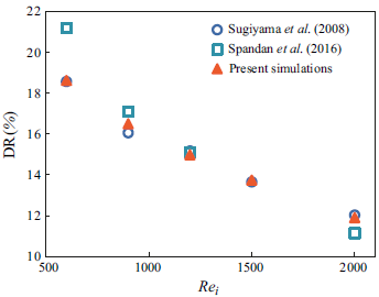
To validate our two-phase simulation code, we investigated the drag reduction effect of rising bubbles in the TC system for
 ${Re}_i$
in the range of 600–2000, as shown in figure 10. The present results are in good agreement with those reported by Sugiyama et al. (Reference Sugiyama, Calzavarini and Lohse2008) and Spandan et al. (Reference Spandan, Ostilla-Mónico, Verzicco and Lohse2016b
). In these validation cases, the geometry of the TC system was fixed with an aspect ratio of
 $\varGamma = 8$
and a radius ratio of
 $\eta = 5/6$
. The global bubble volume fraction
 $\phi _v$
was varied between 0.125 and 0.67, the bubble diameter was set to
 $d_p^* = 0.05$
and the Froude number
 $\textit{Fr}$
ranged from 0.325 to 1.0. Note that for the rising-bubble simulations, the density ratio should be set to zero, and both the equation for the bubbles and the formulation of the feedback force should be modified according to that in Spandan et al. (Reference Spandan, Ostilla-Mónico, Verzicco and Lohse2016b
).
Drag reduction (DR) as a function of the inner Reynolds number
 ${Re}_i$
. The results of the present simulation are compared with those of Sugiyama et al. (Reference Sugiyama, Calzavarini and Lohse2008) and Spandan et al. (Reference Spandan, Ostilla-Mónico, Verzicco and Lohse2016b
).