Introduction
Synthesis of microwave filters, which aims to find a legitimate circuit model that can represent physical realizations of a class of filters, has been a classic theme in the microwave society for more than 80 years. The synthesis of circuit models shows the optimal achievable response and leads to accurate dimensional design for a filter of a given topology. The traditional synthesis method is based on the circuit model with frequency-invariant inverters [Reference Cameron1]. Transmission zeros (TZs) are introduced by cross-couplings in such kind of circuit model. The synthesis of the extracted-pole section is introduced in [Reference Amari and Macchiarella2] to generate TZs by short-circuiting the signal to a dangling route with non-resonant nodes (NRNs). Besides these two circuit models, dispersive coupling, which demonstrates a frequency-dependent characteristic, is also found to be able to introduce TZs [Reference Amari, Bekheit and Seyfert3].
In fact, any physical coupling element inevitably exhibits certain frequency dependence or dispersion effect, which not only affects the performance within the passband but also the out-of-band rejection. Therefore, discarding the dispersion effect in filter synthesis may lead to an unsatisfactory design for both wideband and narrowband filters. In the past decade, attentions have been paid to taking into account the dispersive effect in the filter synthesis for two purposes: (1) to accommodate the needs for wideband filter design [Reference Meng, Lee, Zaki and Atia4, Reference Amari, Seyfert and Bekheit5]; and (2) to explore an alternative approach to create TZs without using cross-couplings or extracted-pole sections as usually done in narrowband filters.
In a dispersive coupling matrix (DCM), the coupling topology is the same as that of the intended filter layout but the coupling elements are dispersive, which are also called resonant or mixed couplings and are found useful to generate TZs close to the passband without using cross-couplings [Reference Levy6–Reference Rosenberg, Amari and Seyfert9]. The mechanism behind such a TZ-generating element is the frequency-dependent characteristic of the couplings on the shortest path.
The evidence of the existence of dispersion effect in narrowband filters can be revealed during the identification of the filtering function even if no coupling structure with a strong dispersion effect is introduced. When extracting a frequency-invariant coupling matrix of a physical filter from the measured response, additional TZs that are far away from the passband are usually necessary such that the filter response can be well fit, resulting in several factitious parasitic couplings [Reference Zhao and Wu10]. This phenomenon indicates that the dispersion effect of a physical filter can be represented by parasitic couplings.
In recent years, more and more efforts have been paid to synthesizing bandpass filters with linearly frequency-dependent mutual couplings [Reference Szydlowski, Leszczynska, Lamecki and Mrozowski11–Reference Zhang, Wu and Seyfert16]. A zero-pole optimization method is utilized to find the DCM to fit a designed rational filtering function [Reference Szydlowski, Leszczynska, Lamecki and Mrozowski11], which provides a reasonably good initial design for EM optimization. An improved dimensional synthesis method is proposed for a filter configuration consisting of open and short stubs [Reference Szydlowski, Leszczynska and Mrozowski12]. Methods by a series of similarity transformation and scaling on the constant coupling matrix are introduced in [Reference Tamiazzo and Macchiarella13, Reference He, Macchiarella, Wang, Wu, Sun, Wang and Zhang14] to find the DCM in folded form and in-line topology, respectively. Very recently, an optimization method on isospectral surfaced is introduced in [Reference Zhang, Meng and Wu15, Reference Zhang, Wu and Seyfert16] to determine the constant part of the DCM whose slope is given.
To establish a synthesis-and-design framework for a general coupled-resonator filter following the nature of physics, a synthesis method based on a “personalized” circuit model that reflects the actual physical characteristics of a given filter realization is introduced in [Reference Zhang, Meng and Wu17]. Based on a nonlinear dispersive circuit model, the synthesis and physical dimension design are in interlaced cycles so that the synthesized circuit model best incorporates the designed physical filter model. However, it is designated to waveguide filters in in-line topologies.
In this paper, a direct synthesis method for the general DCM of a given coupling topology that incorporates both dispersive coupling and cross-coupling is proposed. Such a DCM can accurately represent the physical nature of a coupled-resonator filter with a particular realization. The DCM consists of two parts: a constant coupling matrix, which corresponds to the DCM at the center frequency, and the frequency-dependent part that reflects the dispersion of the physical realization, which is supposed to be known before synthesis. The objective of the synthesis method is to find the constant coupling matrix for a given frequency-dependent part such that an equal-ripple in-band response is achieved. Based on such a composition of the DCM, the design of the physical filter realization can be done by EM simulation at the center frequency only guided by the constant coupling matrix.
To help better understand the proposed synthesis method, the procedure for extracting the dispersion effect of two commonly seen general bandpass filter realizations is first discussed. Then, the detailed theory development and synthesis procedure are presented followed by two synthesis and design examples, which include a transmission line type of filter with unintentional weak dispersions and an LC tank type of filter with intentional strong dispersions. The examples are validated by EM simulation to demonstrate the effectiveness, accuracy, and generality of the proposed synthesis framework.
Extraction of the dispersion effect
The loop equation of a coupled-resonator network in the lowpass domain with resonators represented by shunt capacitors is
 $$ \left[{\matrix{ {i_S} \cr 0 \cr \vdots \cr 0 \cr 0 \cr } } \right] = \left({\left[{\matrix{ {\boldsymbol \vskip-13pt G }{\hskip-5pt \hscale 220% \vscale 330% +}}& {} \cr {}&{} \cr } } \right] + j{\boldsymbol M} + j\Omega \bigg[{\matrix{ {}&{} \cr { \vskip-14pt \hscale 220% \vscale 330%+ } {\vskip -0.7pc\boldsymbol I} } } \!\!\!\!\!\!\bigg]} \right)\left[{\matrix{ {v_S} \cr {v_L} \cr {v_1} \cr \vdots \cr {v_N} \cr } } \right]$$
where G and I are two identity matrices of dimension 2 and dimension N (number of resonators), respectively. Ω is the frequency variable in the lowpass domain. The coupling matrix M becomes a DCM when it is frequency dependent and can be represented as M(Ω) = Md(Ω) + M0, where Md(Ω) represents the nonlinear dispersion effect and M0 = M(0) is the constant term at the center frequency. Two types of commonly used resonators are considered here: the transmission line type and the LC tank resonator type. In this section, the mathematical basis for defining the DCM for the filters with the two types of resonators is discussed.
Couplings of transmission line type of resonators
With the equivalence between the inverter and a T-network [Reference Bui, Ball and Itoh18], the value of the inverter K of a discontinuity is calculated as


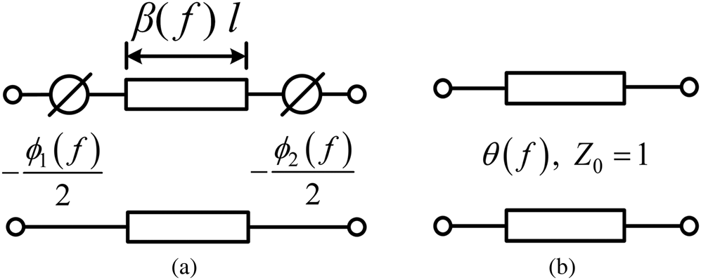
As illustrated in Fig. 1(a), considering the loading effects of the two coupling elements at both ends of the resonator, the total electric length becomes

with β(f) being the propagation constant of the resonant mode. ϕ 1(f)/2 and ϕ 2(f)/2 are the phase shifters of the two coupling elements at the two ends of the resonator.
Circuit models of a transmission line type of resonator with coupling elements at ends. (a) Distributed element circuit model. (b) Transmission line model with a frequency-dependent electric length.

Based on the analysis in [Reference Zhang, Meng and Wu17], the self-coupling elements are

with the reactance slope parameter xi found at f 0 being

The inter-resonator coupling elements are related to the impedance inverter K by [Reference Matthaei, Young and Jones19]


Couplings of LC tank type of resonators
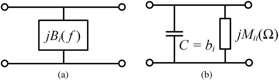
Different from the filters using transmission line type of resonators, the DCM for a coupled-resonator filter using the LC tank type of resonators needs to be numerically extracted at all frequency points by multiport Y-parameters obtained from EM simulation. The Y-parameters are simulated at N artificial ports defined at the strongest electric field spot of each resonator and the two filter parts [Reference Yin20]. It should be mentioned that the spot for defining such an artificial port should be chosen in the way that the current entering into the port tends to be zero. The bandpass circuit model and its lowpass domain counterpart of such a resonator are shown in Fig. 2. With the EM simulated Y-parameters, which are normalized to the port reference admittance, the susceptance B i(f) and admittance inverters Jij(f) can be found as

where 1, … , N are the indexes of the resonators, and S and L are the indexes of the source and load ports, respectively. Then we have the admittance of the resonator of the bandpass model Ybp and the lowpass model Ylp


(a) Bandpass domain; and (b) lowpass domain circuit models of an LC tank type of resonator.

Consequently, the normalized self-coupling Mii(Ω) can be obtained by equating Ybp and Ylp as

where the susceptance slope parameter bi at f 0 can be found by matching the slopes of susceptances Bi(f) and Bl(f) as

or

Then mutual coupling coefficients are determined by scaling as


For these two types of filters, the general DCM can be determined at all frequency points using the provided calculations. Note that DCM is expressed in the form of M(Ω) = M0 + Md(Ω), where M0 = M(0), Md(0) = 0. The required Md(Ω) for the subsequent synthesis can be obtained by

which is in the same coupling topology as that of M0, or the desired coupling topology.
Synthesis of DCM
It is postulated that for a given physical realization, the dispersion of a coupling element does not change too much with the dimension modified in a reasonable range. Thus, one can estimate the dispersion from an initial dimension design of the filter obtained either by intuition or by the dispersive-free coupling matrix. The extracted dispersion effect will be updated progressively as the interlaced synthesis-and-design process goes. Usually, it converges in a few cycles.
The objective of the synthesis is to find the constant part of the DCM such that the return loss achieves an equal-ripple response and the rejection response is stipulated by the specified coupling topology, order of the filter, and given dispersion.
The synthesis is an iterative procedure as follows:
Step 1: Finding the initial constant coupling matrix ${\boldsymbol M}_0^{( 0 ) }$ that satisfies the desired return loss in the passband centered at f 0, without considering the dispersion using the method for dispersion-less coupling matrix. The superscript (i) is the index of iteration i.
Step 2: Determining the characteristic polynomials $P_0^{( 0 ) } ( s ) \;$ and $F_0^{( 0 ) } ( s )$
 of ${\boldsymbol M}_0^{( 0 ) }$
 together with the constant coefficient $\epsilon _0^{( 0 ) }$
 , where s = jΩ. Note that the Belevitch form of the scattering parameters is defined as

where E 0(s), P 0(s), F 0(s), and F 220(s) are all monic polynomials.
The iteration starts with i = 1.
Step 3: Simulating the filter response using the DCM ${\boldsymbol M}( {\rm \Omega }) = {\boldsymbol M}_0^{( {i-1} ) } + {\boldsymbol \;}{\boldsymbol M}_d( {\rm \Omega } )$ . The coefficient $\epsilon _0^{( i ) }$
 is updated by

mainly based on the concept that the responses of M(Ω) and ${\boldsymbol M}_0^{( {i-1} ) }$ should be the same at the center frequency, which is

with the simulated filter response, we can identify the corresponding characteristic polynomials $P_D^{( i ) } ( s ) \;$ and $F_D^{( i ) } ( s )$
 by the model-based vector fitting (MVF) method [Reference Zhao and Wu21]. Vector fitting is a useful mathematical tool that is able to identify the numerator and denominator polynomials of a rational function. MVF is a modified method that is suitable for identifing a filtering function with a prescribed number of poles and zeros. Usually, the order of $P_D^{( i ) } ( s ) \;$
 is higher than that of $P_0^{( {i-1} ) } ( s ) \;$
 but lower than or equal to the order of the filter to reflect the dispersion.
Step 4: Discarding the TZs in $P_D^{( i ) } ( s )$ that are far away from the TZs created by $P_0^{( {i-1} ) } ( s )$
 to form an approximated polynomial $P_a^{( i ) } ( s )$
 .
Step 5: Defining the difference characteristic polynomial as

which is a corrective factor for achieving an equal-ripple response.
Step 6: With the extracted $P_D^{( i ) } ( s )$ , a new polynomial $F_a^{( i ) } ( s )$
 can be obtained using the dispersionless synthesis method such that the two polynomials yield a Chebyshev filtering function. Note that this response is supposed to be the eventual response of the DCM when the whole process converges. The obtained $F_a^{( i ) } ( s )$
 is further used to update $F_0^{( {i-1} ) } ( s )$
 so that it eventually converges to $F_D^{( i ) } ( s )$
 .
Step 7: The characteristic polynomials for ${\boldsymbol M}_0^{( i ) }$ , or $F_0^{( i ) } ( s )$
 and $P_0^{( i ) } ( s )$
 , are updated by

And

except for the filter that has no cross-coupling, for which P 0 (s) = 1. $P_a^{( i ) } ( s )$ is the polynomial whose roots are the TZs obtained from $P_D^{( i ) } ( s )$
 corresponding to the topology of the filter with those far TZs generated by dispersion neglected. With the $F_0^{( i ) } ( s )$
 and $P_0^{( i ) } ( s )$
 ,$\;E_0^{( i ) } ( s )$
 can be found by the Feldtkeller equation and $\;{\boldsymbol M}_0^{( {i-1} ) }$
 is further updated to ${\boldsymbol M}_0^{( i ) }$
 . The iterative process repeats until the response of the updated DCM reaches an equal-ripple response in the passband.
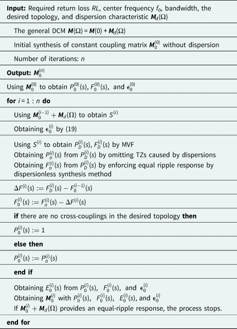
The convergence of the iteration process can be interpreted physically. In each iteration, the only thing we do is to enforce the equal-ripple return loss in the passband with the given dispersion of all the mutual and self-couplings. The final TZs of the synthesized filter are contributed by two parts: the pre-assigned TZs by $P_0^{( 0 ) } ( s )$ and the newly-generated ones contributed by the dispersion effect. To achieve an equal-ripple response in the presence of the dispersion, the pre-assigned TZs need to be altered slightly. The TZs contributed by the dispersion depend on the dispersion characteristics of all the coupling elements including the resonators, which can be manipulated by tactically designing the physical structure and dimensions to achieve the desired TZ distribution. The pseudocode of the synthesis process is given in Table 1.
Pseudo-code of the general synthesis method.

Synthesis examples
To demonstrate the generality of the proposed synthesis method, two demonstrating examples are presented in this section. The examples illustrate the necessity of synthesizing a DCM from two aspects: inevitable weak dispersions that affect the rejection band; strong dispersive couplings to enhance the rejection close to the passband. Both the examples are verified by EM simulation.
A narrowband H-plane waveguide filter
This is a “Hello World” example to show an accurate prediction of the roll-off in the rejection band of a narrow band H-plane waveguide filter with an inevitable dispersion effect. Consider a narrowband waveguide filter with the specifications:
Passband: 3.45–3.55 GHz with 20 dB return loss;
Rejection: 40 dB at 3.63 GHz and 60 dB at 3.7 GHz.
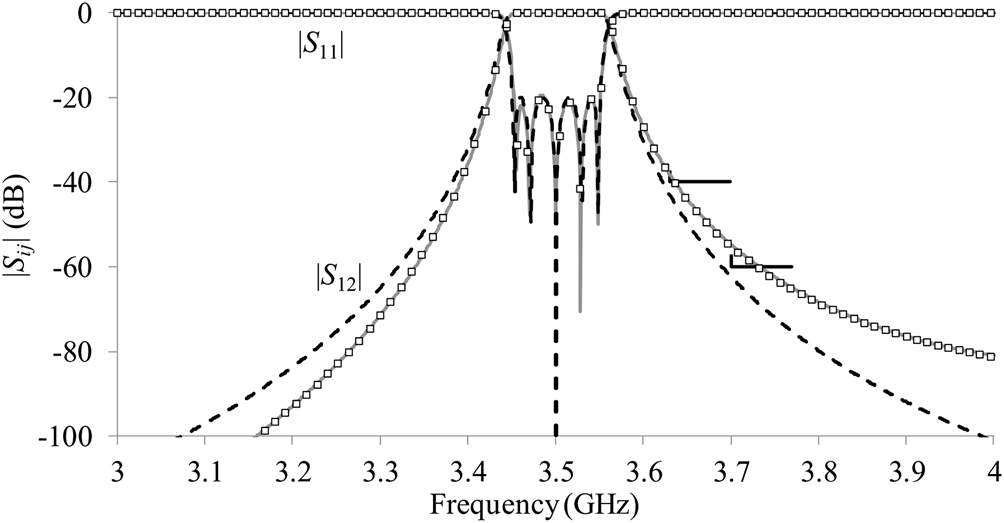
A five-pole filter is initially synthesized by the dispersion-less synthesis method. As shown in Fig. 3, the response of the synthesized coupling matrix satisfies the specifications. Assume that the filter is physically realized by an H-plane waveguide filter using WR229 waveguide (a = 58.17 mm, b = 29.08 mm), for which the impedance inverters are realized by inductive irises. The waveguide filter is EM designed by applying (1)–(4). The EM simulated response of the fifth-order filter is also superimposed in Fig. 3. We can observe that although the synthesized dispersionless fifth-order filter model achieves the rejection specs, the physically realized filter can no longer satisfy them due to the dispersion effect.
Responses of the fifth-order H-plane waveguide filter: by dispersion-less synthesized coupling matrix (dashed lines), by synthesized DCM (solid lines, which is coincide with the square dotted lines), and by EM simulation (square dotted lines).

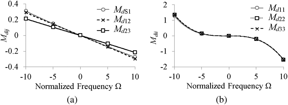
To have a more accurate design, the dispersion of the inductive irises and the transmission line type of waveguide resonators need to be taken into account in the synthesis. With the EM simulation of each iris and the resonator based on the dimensions of the initial design, we can find the dispersion characteristics of each mutual- and self-coupling element as presented in Figs 4(a) and 4(b) applying (1)–(9). It is observed that even for such a simple filter structure, the dispersion of the self-coupling is not linear in a wideband sense.
The dispersion characteristics of the initial EM design of the five-pole waveguide filter: (a) inter-resonator couplings, and (b) self-couplings. Due to the symmetry, only half of the couplings are shown.

Then the proposed general synthesis method is applied to a six-pole H-plane waveguide filter with the dispersion characteristics of an initial design with ${\boldsymbol M}_0^{( 0 ) }$ , which is synthesized with 20 dB return loss. For the in-line topology, $P_0^{( i ) } ( s ) = 1$
 , for all is. Since the dispersion is relatively weak in the passband, a nearly equal-ripple response is obtained with the initial coupling matrix. As a matter of course, the synthesis process converges to a new constant coupling matrix, in three iterations, which is given by
 $${\boldsymbol M}_0 = \left[{\matrix{ 0& {1.0087}& 0& 0& 0& 0& 0& 0 \cr {1.0087}& {0.0329}& {0.852}& 0& 0& 0& 0& 0 \cr 0& {0.852}& {0.0307}& {0.6171}& 0& 0& 0& 0 \cr 0& 0& {0.6171}& {0.0388}& {0.5889}& 0& 0& 0 \cr 0& 0& 0& {0.5889}& {0.039}& {0.6172}& 0& 0 \cr 0& 0& 0& 0& {0.6172}& {0.0305}& {0.852}& 0 \cr 0& 0& 0& 0& 0& {0.852}& {0.0329}& {1.0089} \cr 0& 0& 0& 0& 0& 0& {1.0089}& 0 \cr } } \right]$$
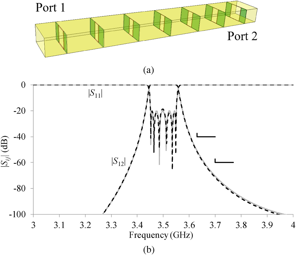
with which a six-pole WR229 waveguide filter shown in Fig. 5(a) can be directly EM designed. The filter response by the synthesized general DCM is compared to that of the EM designed in Fig. 5(b), showing very good agreement. Obviously, the general synthesis method provides an accurate circuit model.
(a) The perspective view of the six-pole H-plane waveguide filter. (b) Responses of the filter by EM simulation (dashed lines) and the synthesized DCM (solid lines).

A coaxial triplet filter using strong dispersive couplings
Recently, a new concept of pseudo-elliptic in-line filter configuration with a close to passband TZ using a strongly coupled-resonator pair (SCRP) is proposed [Reference Bastioli and Snyder22]. An SCRP consists of a pair of relatively close resonators to provide a single resonant node as well as an enhancer of the range of the by-pass couplings that can be realized, thus realizing a triplet. More recently, an ad-hoc direct synthesis method dedicated to such a filter configuration is proposed [Reference Macchiarella, Bastioli and Snyder23]. The synthesis method describes such a filter consisting of strong dispersive resonators using a conventional dispersion-less coupling matrix with a so-called SymBox building block. The circuit model is composed of three non-dispersive resonators, a NRN, and five inter-resonator couplings. The final circuit model is synthesized by a lengthy rotation sequence and approximated transformations without the physical “identity” of the actual resonators.
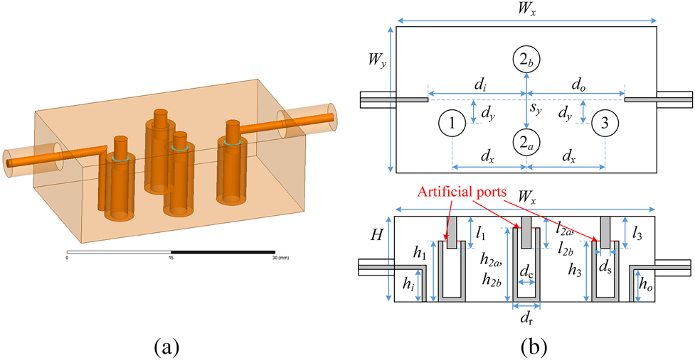
A coaxial filter containing SCRP resonators can be synthesized within the proposed general synthesis framework as a filter with dispersive resonators. The demonstrating filter under consideration in this example is treated as a three-pole filter in a cascaded trisection configuration with the second resonator realized by an SCRP. The center frequency f 0 and the bandwidth BW of the filter are 3.5 GHz and 200 MHz, respectively. A close-to-the-passband TZ in the lower rejection band is realized by the dispersive SCRP resonator. The geometry of the filter structure is depicted in Fig. 6(a). As shown in Fig. 6(b), for simplicity, the SCRP is set to be symmetric such that l 2a = l 2b = l 2 and h 2a = h 2b = h 2. The filter configuration would be treated as a three-pole filter involving a NRN in the dispersion-less circuit model but is accommodated by a three-pole filter with a nonlinear dispersion effect within the proposed framework.
(a) The physical structure of the coaxial three-pole triplet filter with an SCRP resonator. (b) Top and side views of the filter structure and dimensions with the artificial port for computing the dispersion characteristics.

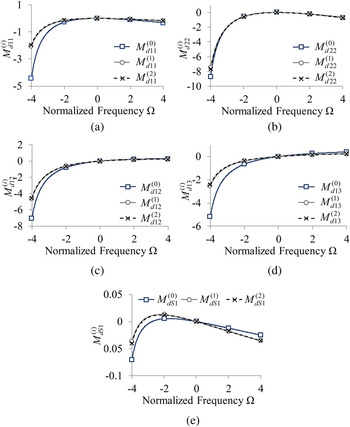
To begin with, all of the dimensions of the resonators are initially designed such that the odd mode resonance of the SCRP and the resonance of resonators 1 and 3 are close to f 0, resulting in a filter response similar to the one shown in Fig. 7. With the artificial ports defined at each resonator, as indicated in Fig. 6(b) and the mathematical model discussed in the “Couplings of LC tank type of resonators” section, the frequency-dependent part of the DCM corresponding to the initial design can be obtained. The frequency-dependent part of typical dispersive couplings in each synthesis-and-design cycle is illustrated in Fig. 8. The frequency dependence of these couplings tends to be stronger at the lower band mainly due to the resonance of the even mode of the SCRP. Those couplings that are away from the SCRP, such as MdS 1, are almost frequency invariant.
Responses of the initial design of the coaxial triplet filter by EM simulation (dashed lines) and by DCM (solid lines).

Frequency-dependent coupling (a) Md 11, (b) Md 22, (c) Md 12, (d) Md 13, and (e) MdS 1 of each synthesis-and-design cycle of the coaxial filter.

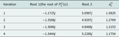
By applying the proposed general synthesis method, a frequency-invariant coupling matrix, which corresponds to the DCM at f 0, is converged in two synthesis-and-design cycles. The initial constant coupling matrix ${\boldsymbol M}_0^{( 0) }$ is targeted to a 20 dB equal-ripple response with a TZ at the normalized frequency −4j. By adjusting the position of this initial TZ, the position of the TZ with dispersion effect can be subsequently tuned. Different from the previous example, a TZ is involved in the configuration of this filter, which means $P_0^{( i ) } ( s )$
 should be updated for each iteration. Taking cycle 2 as an example, the convergence of the iteration process is demonstrated in Table 2 by the roots of $P_d^{( i ) } ( s )$
 and $P_a^{( i ) } ( s )$
 , as well as $\epsilon _0^{( i ) }$
 . The TZ far away from the passband is a parasitic TZ due to the dispersion effect.
Roots of $P_D^{( i ) } ( s )$ , the root of $P_a^{( i ) } ( s )$
 , and $\epsilon _0^{( i ) }$
 of the four iterations in Cycle 2.

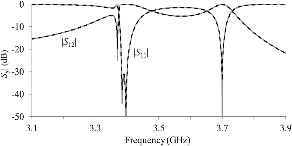
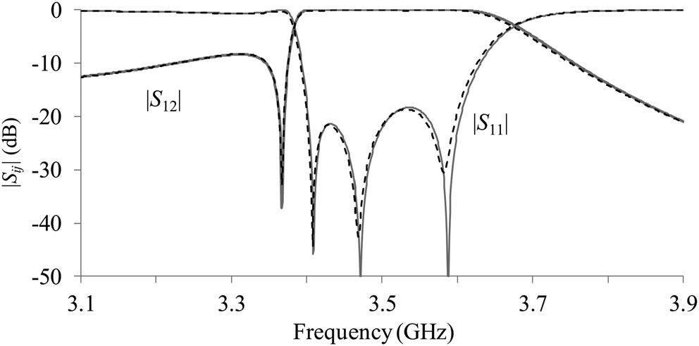
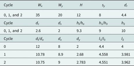
The frequency-dependent part of the dispersive coupling matrices in cycle 1 and cycle 2 are very close, indicating the convergence of the dispersive characteristics. Dimensions at the end of each cycle are listed in Table 3. The corresponding constant coupling matrices obtained at the end of each synthesis-and-design cycle are listed in Table 4. The responses of the synthesized DCM and EM model are superposed in Fig. 9, showing excellent agreement. The final response exhibits a 20 dB equal-ripple return loss, as specified in the synthesis specs, and a very close TZ at the lower rejection band. Note that this synthesis-and-design method is not aimed at prescribed TZs, it only converges to the design with an equal-ripple response. The correct locations of TZs can be further achieved by a trial-and-error process.
Response of the designed coaxial filter by EM simulation (dashed lines), and synthesized DCM (solid lines).

The structure dimensions of two cycles (unit: mm).

The constant coupling matrices at the end of two cycles.

Conclusion
A general filter synthesis-and-design framework to directly obtain the DCM for a given filter realization is proposed in this paper. By taking into account the dispersion characteristics of a specific filter structure, the DCM that able to represent the general filter structure can be directly synthesized. With the synthesized DCM, an accurate EM design is greatly simplified since merely the coupling coefficients at the center frequency need to be matched to those of the EM model. Two demonstrating examples are given to illustrate the necessity of synthesizing a DCM from two aspects: weak dispersive couplings that affect the rejection band and strong dispersive couplings to enhance the roll-off of rejection close to the passband. Both of the examples are very well verified by EM simulation. It is expected that the proposed general filter synthesis framework is a move away from the existing “one model fits all” approaches to the synthesis of a filter with the physical identity of its realization.
 Yan Zhang received the B.S. degree in electronic engineering from the University of Electronic Science and Technology of China, Chengdu, China, in 2017. She is currently pursuing the Ph.D. degree at the Chinese University of Hong Kong, Shatin, Hong Kong. Her current research interests include synthesis and tuning of filters with dispersive couplings and filters with irregular topologies. Ms. Zhang is a recipient of Hong Kong Ph.D. Fellowship.
 Ke-Li Wu (M’90–SM’96–F’11) received the B.S. and M.Eng. degrees from the Nanjing University of Science and Technology, Nanjing, China, in 1982 and 1985, respectively, and the Ph.D. degree from Laval University, Quebec, QC, Canada, in 1989. From 1989 to 1993, he was a Research Engineer with McMaster University, Canada. He joined COM DEV (now Honeywell Aerospace), Cambridge, ON Canada in 1993, where he was a Principal Member of Technical Staff. Since 1999, he has been with The Chinese University of Hong Kong, Hong Kong, where he is currently a Professor and the Director of the Radiofrequency Radiation Research Laboratory. His current research interests include EM-based circuit domain modeling of high-speed interconnections, robot automatic tuning of microwave filters, decoupling techniques of MIMO antennas, and IoT technologies. Prof. Wu is a member of the IEEE MTT-8 Subcommittee. He was a recipient of the 1998 COM DEV Achievement Award and the Asia-Pacific Microwave Conference Prize twice in 2008 and 2012, respectively. He was an Associate Editor of the IEEE Transactions on MTT from 2006 to 2009.