1. Introduction
Metamorphic core complexes (MCC) are defined as “domal structures composed of ductiley deformed rocks and associated intrusions underlying a ductile-to-brittle high-strain zone that experienced tens of kilometres of normal sense displacement in response to lithospheric extension” (e.g. Teyssier & Whitney, Reference Teyssier and Whitney2002; Whitney et al. Reference Whitney, Teyssier, Rey and Buck2013, p. 274). In this widely accepted definition, core complex formation is driven by lithospheric extension, and many are presently located in areas of continental extension such as the Basin and Range Province, western USA (Davis & Coney, Reference Davis and Coney1979; Wernicke, Reference Wernicke1981; Wernicke & Axen, Reference Wernicke and Axen1988) and the Aegean Sea (Lister et al. Reference Lister, Banga and Fenstra1984; Rey et al. Reference Rey, Teyssier, Kruckenberg and Whitney2011). Rey et al. (Reference Rey, Mondy, Duclaux, Teyssier, Whitney, Bocher and Pringent2017) recognized that structures in gneiss domes were commonly contractional but they interpreted these structures as being coeval with regional extension and erosion. Platt et al. (Reference Platt, Behr and Cooper2015) defined MCCs as “products of normal fault displacements sufficient to exhume rocks from below the brittle-ductile transition”, while recognizing that footwall rocks may reflect tectonic processes that pre-date formation of the detachment fault, in addition to those accompanying exhumation. MCCs comprise central domes of high-grade (kyanite, sillimanite) metamorphic rocks, sometimes with migmatites showing interconnected partial melts, overlain by low-grade or unmetamorphosed rocks. The contact is usually a 1–2 km thick ductile shear zone with mylonites and a brittle detachment showing extensional fabrics. These low-angle normal faults have been the subject of much debate; it is generally thought that normal faults initiate at high angles (c. 70–60°) and that low-angle faults with dips of less than 30° cannot slip (Anderson, Reference Anderson1951).
Models representing modes of crustal extension can be broadly grouped into two types: a pure shear extension model (McKenzie, Reference McKenzie1978), and a simple shear extensional model (Wernicke, Reference Wernicke1981), with a hybrid model proposing simple shear extension in the upper crust and pure shear extension in the ductile lower crust (Fig. 1). Since active slip on low-angle normal faults breaks the ‘rules’ of Andersonian mechanics theory, a conundrum has developed. It was then suggested that low-angle normal faults were initiated at high angles, and were subsequently rotated to lower angles by isostatic adjustments during further extension (the rolling-hinge model; Fig. 1d; Buck, Reference Buck1988; Buck et al. Reference Buck, Martinez, Steckler and Cochran1988). This model predicts a significant amount of rotation in the footwall, where faults were formed at steep angles and rotated passively to low angles with exhumation and displacement. ‘Andersonian’ rock mechanics theory conflicts with an increasing amount of field geological data that suggest low-angle normal faults are widespread, can develop at low angles (Axen, Reference Axen1999; Axen, Reference Axen2007) and can also be present in compressional mountain ranges (Burg et al. Reference Burg, Guirard, Chen and Li1984; Searle, Reference Searle2010, Reference Searle2013; Cooper et al. Reference Cooper, Adams, Edwards and Hodges2012).
Simplified diagrams illustrating the main models proposed to explain crustal extension. (a) Pure shear extension model of McKenzie (Reference McKenzie1978). Symmetrical extension with steep normal faults in the brittle upper crust, outwards ductile flow in the lower crust and passive upwelling of hot mantle. (b) Hybrid model showing asymmetric extension and low-angle normal faulting in the upper crust and pure shear extension in the lower crust. (c) Simple shear extension model of Wernicke (Reference Wernicke1981), with simple shear in the upper and lower crust, a low-angle detachment cutting the entire crust and development of a metamorphic core complex by rising dome of lower crust. (d) The rolling-hinge model (Buck, Reference Buck1988, Reference Buck1991; Wernicke & Axen, Reference Wernicke and Axen1988), where the active part of the fault is steeply dipping and faults are progressively flattened as they are stranded above domes. BDT – brittle–ductile transition.

Since the first descriptions of gneiss domes by Eskola (Reference Eskola1949), a number of mechanisms have been proposed to explain the origin of core complexes (e.g. Yin, Reference Yin and Whitney2004). These include three main categories of core complex formation: (a) during crustal thinning and lithospheric scale, simple shear extension with a component of isostatic rebound (Wernicke, Reference Wernicke1981; Davis, Reference Davis1983; Lister et al. Reference Lister, Banga and Fenstra1984; Wernicke & Axen, Reference Wernicke and Axen1988) or transtension (McFadden et al. Reference McFadden, Teyssier, Siddoway, Whitney and Fanning2010), (b) diapirism as a result of Rayleigh–Taylor instability, partial melting and density inversion (Ramberg, Reference Ramberg1981; Rey et al. Reference Rey, Vanderhaegue and Teyssier2001; Vanderhaege & Teyssier, Reference Vanderhaege and Teyssier2001; Teyssier & Whitney, Reference Teyssier and Whitney2002), or combinations of these, and (c) during crustal contraction by superposed folding (Ramsay, Reference Ramsay1967), doming above a thrust ramp (Burg et al. Reference Burg, Guirard, Chen and Li1984), partial melt-induced channel flow (e.g. Godin et al. Reference Godin, Grujic, Law, Searle, Law, Searle and Godin2006; Searle et al. Reference Searle, Law, Jessup, Law, Searle and Godin2006, Reference Searle2010; Cottle et al. Reference Cottle, Searle, Horstwood and Waters2009, Reference Cottle, Searle, Jessup, Crowley and Law2015) or transpressional uplift (e.g. Matte, Reference Matte2007).
This paper deals with three major debates concerning: (1) the evolution of the metamorphic core and how rocks that formed at lower crustal depths were uplifted to high structural levels; (2) low-angle ductile shear zones and normal faults that bound the upper level of MCCs, and (3) extensional fabrics in compressional orogenic settings. This can potentially explain the apparent conflict between compressional structures in the core of the domes and extensional structures in the overlying carapace. We refer readers to the excellent reviews of MCCs on which we base our discussion, particularly Wernicke & Burchfiel (Reference Wernicke and Burchfiel1982), Teyssier & Whitney (Reference Teyssier and Whitney2002), Whitney et al. (Reference Whitney, Teyssier, Rey and Buck2013) and Platt et al. (Reference Platt, Behr and Cooper2015). Firstly, we review the three main components of an MCC: the metamorphic core, the low-angle normal-sense detachment and the overlying extensional carapace. We discuss the main geological models for MCC formation, and ask the key questions that could support or negate the standard extension models for core complex formation.
We then discuss a few key examples of MCCs in compressional tectonic settings. Foremost of these examples are the North Himalayan gneiss domes such as Tso Morari (NW India), Kangmar and Mabja domes (Tibet), and the metamorphic domes in the Greater Himalaya, notably the Nanga Parbat core complex in the Western Himalaya. Other MCCs occur in the Karakoram (Dassu dome) and the Pamir (Kongur Shan–Muztagh Ata domes). All these MCCs were formed as a result of crustal burial, regional Barrovian metamorphism, partial melting and major compressional tectonics, and occur in mountain belts that are still under compressive forces today. Finally, we reinterpret metamorphic rocks in the core of the Naxos dome in the Aegean as related to early compression, involving isoclinal folding and thrusting, burial, kyanite–sillimanite-grade metamorphism and migmatitic flow, followed by later regional Aegean Sea extension. Folding of the young low-angle normal fault around the island may indicate an even younger phase of compression. We show that many core complexes were formed in actively compressional tectonic settings and are related to concomitant deep-level thrusts beneath and high-level low-angle normal faults above, or to post-metamorphic crustal-scale folding.
2. Metamorphic cores
A global review of MCCs shows that a wide range of metamorphic histories characterize the internal cores of the MCC. Platt et al. (Reference Platt, Behr and Cooper2015, p. 10) state that “It is now universally accepted that MCCs are the product of a distinctive style of extensional tectonics”, yet they go on to surmise that “The origin of gneiss domes is much debated and it is likely that many of them are formed by processes other than horizontal extension”. In some definitions of MCCs, the age of metamorphism and ductile flow in the core of the dome is related to dome formation. Rey et al. (Reference Rey, Mondy, Duclaux, Teyssier, Whitney, Bocher and Pringent2017) state that “Structures in gneiss domes are commonly contractional yet are coeval with regional extension and denudation”. Deep crustal ductile rocks flow into the gneiss domes in which contractional strain dominates, while boundary-driven extension develops in the shallow crust (Rey et al. Reference Rey, Teyssier, Kruckenberg and Whitney2011, Reference Rey, Mondy, Duclaux, Teyssier, Whitney, Bocher and Pringent2017; Teyssier, Reference Teyssier2011). Key points in these interpretations are that (a) compression in the deep crust is concomitant with extension in the shallow crust; and (b) metamorphism must also be coeval with extension. Whitney et al. (Reference Whitney, Teyssier, Rey and Buck2013) state that “Core complex formation is driven by lithospheric extension”. Rey et al. (Reference Rey, Teyssier, Kruckenberg and Whitney2011) also state that “horizontal shortening on the infrastructure develops in an overall extensional setting”. Since many Himalayan, Karakoram, Pamir and Aegean core complexes exhume regional kyanite- and sillimanite-grade gneisses formed at pressures in excess of 8–12 kbar, this implies that extension can exhume rocks from lower crustal depths as deep as 30–45 km. The causes of metamorphism are either: (a) compressional crustal thickening processes associated with increasing pressure (P) and temperature (T), or (b) extensional crustal thinning with removal of mantle lithosphere and possible delamination (England & Houseman, Reference England and Houseman1989). The clockwise P–T paths and kyanite-grade conditions of metamorphism in MCCs suggest that crustal thickening was more likely, as the latter extensional model would require isobaric heating at lower pressure and higher temperature.
In the standard model for Cordilleran-type or Aegean-type MCC, an original layered crust includes a brittle upper crust showing extensional fabrics lying above one or two detachments that overlie a ductile lower crust (Fig. 2a). As the MCC develops, the ductile lower crust flows into the gneiss dome resulting in a mass excess within the dome and mass deficit of lower crust outside the dome (Fig. 2b). This model implies a horizontal detachment separating the extending upper crust (verging radially away from the dome) from the compressional lower crust (flowing into the dome). Area balancing implies that the Moho should rise beneath MCC domes, or there has to be mass flow of lower crustal material into the dome area in order to maintain a flat Moho. Some models imply diapiric ascent of partially molten migmatites and granites, for example in Naxos (Vanderhaeghe, Reference Vanderhaeghe and Siddoway2004). Diapirism implies molten material in the dome physically rising, intruding through the surrounding country rock, like an intruding granite diapir. Other models suggest a combination of buoyancy-driven flow and regional extension (Kruckenberg et al. Reference Kruckenburg, Vanderhaeghe, Ferré, Teyssier and Whitney2011). For the Naxos dome Kruckenberg et al. (Reference Kruckenburg, Vanderhaeghe, Ferré, Teyssier and Whitney2011) showed that the inner core of the dome contains tight, upright folds with steeply plunging lineations and fold hinges. In this model, horizontal inflow of ductile rocks was primarily driven by pressure differences as a result of rifting.
Characteristics of a Naxos-type metamorphic core complex showing (a) restoration of normal thickness (c. 35 km) crust with future faults (dashed lines) and flow directions (dashed arrows) illustrated; and (b) MCC formation with a brittle extending upper crust (blue) lying above a ductile compressing middle crust (green) and lower crust (brown). The middle crust shows tight isoclinal folds and high-pressure metamorphism. The lower crust in the core of the dome shows kyanite- and sillimanite-grade metamorphism (pressures of c. 7–10 kbar), upright folds, steep lineations and ductile structures cut by the overlying low-angle normal-sense detachments. Note that the boundary between the outwards-moving brittle upper crust and the inwards-flowing middle and lower crust along the brittle–ductile transition (BDT) has to be a major subhorizontal detachment. UHP – ultra-high pressure.

In the extensional core complex model, a vertical thinning of up to 10–20 km and a horizontal component of several tens of kilometres is implied (Platt et al. Reference Platt, Behr and Cooper2015). Core complexes along the North American Cordillera occur along the Sevier–Rocky Mountain belt, a zone of older, thickened continental crust (Davis et al. Reference Davis, Lister and Reynolds1986; Coney & Harms, Reference Coney and Harms1984). Barrovian facies metamorphism and associated partial melting in these core complexes is Late Cretaceous in age, formed during Cordilleran compressional tectonic events (Parrish et al. Reference Parrish, Carr and Parkinson1988; Miller & Gans, Reference Miller and Gans1989), long before the initiation of Basin and Range extension and the formation of the Miocene–Recent low-angle normal faults (Wernicke, Reference Wernicke1981).
Several MCCs, for example Tso Morari, Ladakh Himalaya (e.g. St-Onge et al. Reference St-Onge, Rayner, Palin, Searle and Waters2013), D’Entrecasteaux Island, Papua New Guinea (Baldwin et al. Reference Baldwin, Webb and Monteleone2008; Little et al. Reference Little, Hacker, Gordon, Baldwin, Fitzgerald, Ellis and Korchinski2011) or As Sifah eclogites, Oman (Searle et al. Reference Searle, Waters, Martin and Rex1994; Agard et al. Reference Agard, Searle, Alsop and Dubacq2010), contain high-pressure (HP) blueschists and/or ultra-high-pressure (UHP) eclogites within the dome, and the depths of exhumation required for these may be c. 100 km or more. In all these cases, the UHP metamorphism occurs prior to exhumation along the footwall of high-angle normal faults, prior to regional Barrovian metamorphic overprinting, prior to dome formation and prior to low-angle normal faulting (Fig. 3). Exhumation mechanisms in these UHP eclogites involve return flow up the subduction channel, and the metamorphism or the ductile structures are not related to core complex dome formation at all.
Model showing how eclogites are exhumed from subduction zones beneath obducting ophiolites such as Oman. Prograde burial and (U)HP metamorphism occurs at pressures of > 22 kbar. Following slab break-off, the continental crustal rocks with (U)HP eclogite boudins return towards the surface along ductile shear zones, driven by buoyancy. Large pressure jumps are recorded in the right-way-up metamorphic sequence from eclogite through blueschist to carpholite grade and finally up to the ophiolite (after Searle et al. Reference Searle, Simpson, Law, Parrish and Waters2004).

The key questions, and data needed to test the extensional model for MCC formation are as follows. (1)Is metamorphism in the core older than, or synchronous with, the timing of motion along the upper bounding detachment and extension in the carapace above? (2) Are the folds and fabrics in the core truncated by the detachment above? (3) Can regional Barrovian facies, kyanite- and sillimanite-grade rocks metamorphosed at pressures of c. 10–12 kbar, be exhumed in an active rifting extensional tectonic environment?
3. Low-angle normal-fault ductile shear zones and detachments
The lower metamorphic core regions of MCCs are usually overlain by a low-angle, normal-sense ductile shear zone or detachment fault. These can be overprinted by, or cut above by, a brittle low-angle normal fault (LANF). LANFs are important anomalies, because they do not conform to Andersonian mechanical theory which states that a normal fault should be initiated at dip angles of c. 60° and should not slip if at an angle of less than 30° (Anderson, Reference Anderson1942; Sibson, Reference Sibson1985). Few earthquakes have been recorded on normal faults with dips of less than 30°, although there are exceptions, for example in the Woodlark basin, Papua New Guinea (Abers et al. Reference Abers, Mutter and Fang1997; Axen, Reference Axen1999, Reference Axen2007). It is quite likely that LANFs might creep aseismically, leaving no record of earthquakes (Axen, Reference Axen1999). From laboratory experiments, slip on LANFs requires low friction (Byerlee, Reference Byerlee1978) or rotation of the stress field (Yin, Reference Yin1989). Partial melting reduces the friction and increases the buoyancy forces that make it easier for the rocks to flow. The rolling-hinge model was suggested to explain how LANFs that started as high-angle faults were progressively rotated towards shallower dips (Fig. 1d; Wernicke, Reference Wernicke1981; Buck, Reference Buck1988; Wernicke & Axen, Reference Wernicke and Axen1988). This model is now widely accepted as explaining many LANFs, and fits with observations of rotated detachment faults and footwalls of oceanic core complexes (e.g. Smith et al. Reference Smith, Escartín, Schouten and Cann2008).
LANFs have been described from a variety of different tectonic regimes, including regions under extensional stress such as the Basin and Range (Wernicke, Reference Wernicke1981; Davis et al. Reference Davis, Lister and Reynolds1986; Cooper et al. Reference Cooper, Platt and Behr2017), and regions under compressional stress such as the Himalaya (South Tibetan Detachment, STD). Brittle LANFs generally overlie a zone of ductile mylonites and ultra-mylonites that can often be correlated with the brittle–ductile transition zone. Cooper et al. (Reference Cooper, Platt and Behr2017) defined a structurally lower localized distributed transition (LDT) zone within the ductile lower crust. Brittle faults can also overprint earlier mylonites as the exhumation process progresses and rocks moved upwards into the upper crust brittle regime. In the Basin and Range, LANFs are dominantly of Miocene age and cut older metamorphic rocks in the footwall. Gneisses beneath the Miocene low-angle detachments in the Shushwap (Canada), Whipple Mountains, Snake Ranges and Ruby Mountains (western USA) core complexes formed during the Cordilleran orogenic contraction in the Mesozoic (Parrish et al. Reference Parrish, Carr and Parkinson1988; Cooper et al. Reference Cooper, Platt and Behr2017), and are therefore not related to regional Cordilleran extension at all. The Whipple Mountains detachment and LANF has a minimum displacement of 40 km (Davis et al. Reference Davis, Lister and Reynolds1986), although others could be considerably larger. There is much debate about whether these LANFs are actually active at low angles, or whether they represent giant landslides (Anders et al. Reference Anders, Christie-Blick and Walker2006; Christie-Blick et al. Reference Christie-Blick, Anders, Wills, Walker, Renik, Karner, Manatschal and Pinheiro2007).
In the Aegean, Lister et al. (Reference Lister, Banga and Fenstra1984) interpreted the Ios and Naxos core complexes as mid-crustal metamorphic rocks “drawn upwards and outwards from underneath sedimentary basins now 100 km to the south between ∼25 – 11 Ma”. Although the direction of normal-sense motion on Naxos has been shown to be the opposite to this original statement (top-to-NE), this classic interpretation of metamorphism and exhumation during regional extension has remained largely unchanged. The Naxos dome has a classic MCC structural geometry (Fig. 2b) with a high-grade inner core composed of kyanite and sillimanite gneisses and migmatites with upright folds truncated by a ductile detachment, above which are kyanite-grade gneisses and marbles metamorphosed at lower crustal depths and tightly folded (Koronos Unit; Lamont et al. Reference Lamont, Searle, Roberts, Waters, Palin, Smye, Dyck, Gopon, Weller and St-Onge2019). These rocks are truncated above by a greenschist facies shear zone which places older blueschists (Zas Unit; Lamont et al. Reference Lamont, Searle, Roberts, Waters, Palin, Smye, Dyck, Gopon, Weller and St-Onge2019; part of the Cycladic Blueschist Unit) that underwent a completely different metamorphic cycle to the underlying Barrovian facies rocks. All these rocks are truncated above by the regional low-angle normal fault that wraps around the dome that was active since 15 Ma (Lamont T, PhD thesis, University of Oxford, 2018). Structural mapping shows that ductile fabrics, folds, lineation and metamorphism in the high-grade metamorphic rocks occurred prior to regional extension and the overlying LANF.
The key questions and data needed to interpret the origin of LANF and ductile shear zones are as follows. (1) Was the LANF initiated at a low angle (< 30°) or was it passively rotated from a higher angle after slip? (2) Are the fold axes and fabrics beneath cut by later LANF motion, or do they merge into alignment with the shear zone? (3) Is the age of motion along the LANF synchronous with footwall metamorphism or later than metamorphism?
4. Extensional fabrics in compressional tectonic settings
Extensional fabrics and normal faults in mountain belts are widespread and have often been used to assume late orogenic collapse following mountain building (e.g. Dewey, Reference Dewey1988). However, these extensional fabrics are known across mountain belts that have always been under compression. It is possible to get such fabrics in several tectonic scenarios: (1) by return flow along a subduction channel, for example in exhumed high-pressure eclogites and blueschists (e.g. Oman; Fig. 3); or (2) by channel flow whereby high-grade gneisses, migmatites and leucogranites are exhumed along the top of a crustal-scale low-angle normal fault (e.g. STD along the Himalaya; Fig. 4). In both cases, early subduction processes have buried the rocks to mantle depths (UHP terranes) or deep crustal depths (Himalaya) during prograde metamorphism. Some sort of process ends this prograde, subduction and burial path, slab break-off in the case of UHP rocks, and partial melting and buoyancy forces in the case of Himalayan rocks. Buoyancy forces the rocks to exhume back along the top of the channel whereby higher-pressure rocks are exhumed upwards and juxtaposed against lower-pressure rocks at a higher structural level. This return-flow process (England & Holland, Reference England and Holland1979) is supported by the discovery of tensional earthquakes lying immediately above compressional earthquakes in the eclogitized layer of the Pacific subduction zone (Nakajima et al. Reference Nakajima, Uchida, Hasegawa, Hacker and Kirby2013).
Himalayan channel-flow model showing the ductile extrusion of a partially molten mid-crustal layer bounded by Main Central Thrust (MCT) fault and ductile shear zone below, and the South Tibetan Detachment (STD) low-angle normal fault and ductile shear zone above (after Searle and Rex, Reference Searle and Rex1989; Searle et al. Reference Searle, Simpson, Law, Parrish and Waters2003, Reference Searle, Law, Jessup, Law, Searle and Godin2006). Note the inverted and condensed metamorphic isograds above the MCT zone and the right-way-up isograds along the top of the slab beneath the STD low-angle normal fault and ductile shear zone. Note also the top-to-south thrust-related shear fabrics along the south and the top-to-north extensional fabrics along the sillimanite + K-feldspar + melt migmatite zone in the upper part of the GHS. Bt – biotite; Grt – garnet; Kfs – K-feldspar; Ky – kyanite; St – staurolite.

This return-flow mechanism has been proposed both for exhuming eclogites in Oman (Searle et al. Reference Searle, Warren, Waters and Parrish2004) and in the Tso Morari dome, Ladakh Himalaya (Epard & Steck, Reference Epard and Steck2008; St-Onge et al. Reference St-Onge, Rayner, Palin, Searle and Waters2013). Along the main Himalayan range, the STD is a low-angle ductile shear zone with a brittle fault at the top that crops out for nearly 2000 km along-strike from NW India to SE Tibet (e.g. Burg et al. Reference Burg, Guirard, Chen and Li1984; Burchfiel & Royden, Reference Burchfiel and Royden1985; Searle, Reference Searle1986, Herren Reference Herren1987). The STD is a N-dipping ductile shear zone and normal fault that separated low-grade or unmetamorphosed sedimentary rocks above from high-grade metamorphic rocks and migmatites below. In Nepal, the STD shear zone separated rocks formed at 7–9 kbar (c. 25–30 km burial) from rocks never buried below c. 2 kbar (Searle, Reference Searle2010). The E–W-striking STD can be mapped in three dimensions along N–S-aligned glaciers and valleys that have eroded through the carapace. Along the Rongbuk glacier, north of Mount Everest, mapping has shown that minimum offsets along the STD (dips of 3–20° north) measure 110 km (Searle et al. Reference Searle, Simpson, Law, Parrish and Waters2003, Reference Searle, Law, Jessup, Law, Searle and Godin2006; Law et al. Reference Law, Searle and Simpson2004, Reference Law, Searle and Godin2006; Cottle et al. Reference Cottle, Searle, Jessup, Crowley and Law2015), and in Bhutan at least 70 km offset has been measured (Cooper et al. Reference Cooper, Adams, Edwards and Hodges2012). These minimum offsets show that the STD could not have been initiated at a high angle and subsequently rotated to lower angles, ruling out the rolling-hinge model. Early ductile shearing along the STD was active at low angles during the Oligocene–Miocene sillimanite-grade metamorphism and, during exhumation, became the brittle LANF mapped along the top of the zone. The STD was the passive roof fault beneath which southwards extrusion of partially molten rocks of the Greater Himalaya were extruded to the south during Miocene time (channel flow). Late-stage folding has up-warped the STD to wrap around the North Himalayan gneiss domes (Fig. 4).
In core complexes such as Naxos both mechanisms have occurred, the first during the Eocene expulsion of eclogites and blueschists from the subduction zone (Peillod et al. Reference Peillod, Ring, Glodny and Skelton2017), and the second during Miocene extrusion of the kyanite- and sillimanite-grade migmatites from the core of the dome (Lamont et al. Reference Lamont, Searle, Roberts, Waters, Palin, Smye, Dyck, Gopon, Weller and St-Onge2019). Both these phases of extensional shear occurred during overall regional compression, and pre-dated the major late Miocene – present phase of lithospheric extension across the Aegean Sea (Jolivet & Brun, Reference Jolivet and Brun2010).
5. North Himalayan domes
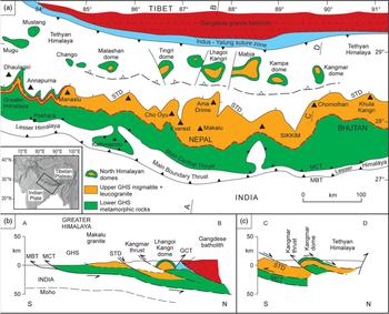
The North Himalayan domes are a series of about 12 MCCs aligned E–W along the northern Tethyan Himalaya, south of the Indus–Yarlung suture zone (Fig. 5). They comprise high-grade regional metamorphic rocks, migmatites and leucogranites that are identical in lithology, age, P–T conditions and structures to the Greater Himalayan Sequence (GHS) rocks to the south (Lee et al. Reference Lee, Hacker, Dinklage, Wang, Gans, Calvert, Wan, Chen, Blythe and Mcclelland2000, Reference Lee, Hacker and Wang2004). The North Himalayan domes show similar geometries to other core complexes, but occur within the entirely compressional setting of the India–Asia collision zone. The domes have folded ductile-to-brittle shear zones surrounding the inner gneissic core. Metamorphic-grade and -deformation temperatures increase structurally downwards towards a sillimanite zone with abundant migmatite and crustal-melt leucogranite. Microstructures generally show a major component of pure shear (40–60%; Langille et al. Reference Langille, Lee, Hacker and Seward2010b) with compressional top-south fabrics at lower levels, overprinted by opposing shear sense with top-north extensional fabrics beneath the overlying ductile shear zone.
(a) Simplified geological map of the Nepal – South Tibet Himalaya, showing the main Greater Himalayan sequence (GHS) bounded by the Main Central Thrust (MCT) along the base and the South Tibetan Detachment (STD) low-angle normal fault along the top. Also shown are the North Himalayan metamorphic core complexes. (b, c) schematic cross-sections across the GHS and the core complexes in South Tibet.

Lu–Hf garnet ages of 52–54 Ma in Mabja and 49–51 Ma in Kangmar show that garnet growth during contractional deformation in the middle crust started synchronously with the early Eocene India–Asia collision (Smit et al. Reference Smit, Hacker and Lee2014a, b). U–Pb zircon ages from the Mabja dome show that peak metamorphism occurred at 35–32 Ma and melting at c. 22.5–16 Ma (Lee & Whitehouse, Reference Lee and Whitehouse2007), closely similar to ages from the GHS to the south. Compressional deformational fabrics are clearly syn-metamorphic and are only overprinted at the highest structural levels approaching the upper detachment of the core complex. The age range and fabrics within the North Himalayan domes is similar to that of the GHS, and seismic imaging strongly suggests that GHS mid-crustal gneisses and migmatites are continuous northwards to the North Himalayan domes.
The North Himalayan domes are surrounded by unmetamorphosed Tethyan sedimentary rocks, from which they are separated by a ductile shear zone and low-angle normal fault that has compressed the right-way-up metamorphic isograds in the footwall by a combination of pure shear flattening and simple shear, and has been folded around the dome. The North Himalayan domes are interpreted as the northern extension of the GHS and the detachment that overlies the metamorphic rocks is the northern extension of the STD low-angle normal fault. The STD is the passive roof fault that formed the upper lid on the southwards extruding mid-crustal channel during Miocene time (e.g. Searle et al. Reference Searle, Simpson, Law, Parrish and Waters2003, Reference Searle, Law, Jessup, Law, Searle and Godin2006; Law et al. Reference Law, Searle and Simpson2004; Godin et al. Reference Godin, Grujic, Law, Searle, Law, Searle and Godin2006). Crustal extension or diapirism had no role in the formation of the North Himalayan domes.
6. Greater Himalayan gneiss domes
Gneiss domes also occur along the main Himalayan range within the core of the Greater Himalaya, as well as the two syntaxes (Nanga Parbat in the west, Namche Barwa in the east). The Leo Pargil dome (Langille et al. Reference Langille, Jessup, Cottle, Lederer and Ahmad2012), the Gurla Mandata dome (Nagy et al. Reference Nagy, Godin, Antolin, Cottle and Archibald2015) and the Ama Drime dome (Jessup et al. Reference Jessup, Newell, Cottle, Berger and Spotila2008; Langille et al. Reference Langille, Jessup, Cottle, Newell and Seward2010a) are all northern extensions of the Greater Himalayan Sequence and are physically connected to the main GHS. These rocks share a metamorphic and deformation history with the GHS, but also show later E–W-oriented extensional fabrics related to orogen-parallel extension. Major high-angle normal faults bound the gneiss domes, which have a morphology similar to core complexes. These faults offset or cut the STD in places and are clearly later than the main Himalayan southwards extrusion (channel flow). All of the structures and metamorphism within these domes relate to crustal thickening processes prior to late extensional fabrics. These extensional fabrics are related more to crustal shortening and culmination of the domes by deeper level thrusting and not to any whole-scale lithospheric E–W extension.
The Ama Drime massif NE of Mount Everest in south Tibet (Fig. 5) shows an intermediate stage in the formation of a core complex (Jessup et al. Reference Jessup, Newell, Cottle, Berger and Spotila2008; Langille et al. Reference Langille, Jessup, Cottle, Newell and Seward2010a). North of Mount Everest, the STD low-angle normal fault which marks the structural top of the GHS gneisses, migmatites and leucogranites is exposed for some 70–80 km along the Rongbuk glacier, providing a unique window into the detachment and the GHS beneath (Searle et al. Reference Searle, Simpson, Law, Parrish and Waters2003, Reference Searle, Law, Jessup, Law, Searle and Godin2006; Cottle et al. Reference Cottle, Searle, Jessup, Crowley and Law2015). East and north of Mount Everest the GHS overlies deeper structural levels of the Ama Drime massif that, in the north, are offset by later brittle structures. Structurally, the Ama Drime massif forms the northern extension of the GHS, but it protrudes north of the STD and is presently bounded by steep active normal faults on both west and east flanks (Cottle et al. Reference Cottle, Jessup, Newell, Searle, Law and Horstwood2007; Jessup et al. Reference Jessup, Newell, Cottle, Berger and Spotila2008; Langille et al. Reference Langille, Jessup, Cottle, Newell and Seward2010a). The Ama Drime massif has the morphology of a classic core complex with a central dome of high-grade gneisses with leucogranite sills and dykes surrounded by typical GHS gneisses above. The Ama Drime gneisses have considerably older protoliths (as old as Palaeoproterozoic) and these rocks have been exhumed from lower crust levels. Garnets from granulitized eclogites have Lu–Hf ages of 34–38 Ma, suggesting that Himalayan crust was already thickened by middle–late Eocene time (Kellet et al. Reference Kellet, Cottle and Smit2014). We suggest that the exhumation of granulitized eclogites and gneisses from depths of c. 60 km in the Ama Drime massif was driven by compressional thrusting at depth with STD-type extensional fabrics above, not orogen-parallel extension (Jessup et al. Reference Jessup, Newell, Cottle, Berger and Spotila2008). The latter process, exemplified by the eight major N–S-aligned graben systems across southern Tibet, only accounts for a minor amount of horizontal extension (c. 20 km) in the upper 10–15 km of the crust, and is insufficient to account for the exhumation of deep Proterozoic rocks, metamorphosed to eclogite and granulite facies during Eocene time at Ama Drime. Normal faults in Tibet do not equate to orogenic collapse at all. Both the crust of the Himalaya and Tibetan plateau are structurally thick (65–75 km) and topography is high (c. 5 km average) today. The entire Himalaya–Tibet regions remains under overall N–S compression and there is no evidence of orogenic collapse, a lowering of surface elevation or a thinning of the crust anywhere.
Several domes composed of sillimanite-grade gneisses and migmatites occur at the deepest structural levels of the GHS in the Indian Himalaya (Figs 6, 7). These domes have all the characteristics of an MCC with a high-grade core surrounded by progressively lower-grade rocks, capped by a ductile shear zone and low-angle normal fault (Zanskar Shear Zone or ZSZ, western equivalent of the STD). Prograde kyanite-grade Barrovian metamorphism in the Gianbul dome, dated at 37–33 Ma, was followed by sillimanite- ± cordierite-grade decompression culminating in partial melting and migmatization at 26–21 Ma (Horton et al. Reference Horton, Lee, Hacker, Bowman-Kamaha’o and Cosca2015). Extensional fabrics along the top of the GHS from the dome up to the ZSZ (STD) are related to exhumation of the gneisses beneath the passive roof fault (Searle & Rex, Reference Searle and Rex1989; Searle et al. Reference Searle, Stephenson, Walker and Walker2007). During Miocene channel flow, the mid-crustal GHS was extruded SW-wards, bounded by the MCT ductile shear zone with its inverted metamorphic field gradient beneath, and the ZSZ with its right-way-up isograd sequence above (Fig. 4). The extension along the ZSZ is purely relative motion with south or SW expulsion of footwall rocks below relative to the static hanging-wall rocks. It is clear that both domal structures wholly within the GHS (e.g. Suru dome, Gianbul dome, etc.) and the Tso Morari North Himalayan dome were formed in an overall compressional stress field, and are not related to any lithospheric or crustal extension. The GHS in the western Himalaya has been under compression since the 50 Ma India–Asia collision and remains under NE–SW compression to this day.
Simplified geological map of the Western Himalaya in north India showing the main Greater Himalayan Sequence with deep-level gneiss domes and the Tso Morari complex in the north, part of the North Himalayan metamorphic core complexes.

Three simplified cross-sections across the Indian Himalaya (locations shown in Fig. 6). Metamorphic isograds are inverted and compressed above the Main Central Thrust (MCT) along the south and the right way-up and compressed beneath the South Tibetan Detachment or Zanskar Share Zone (ZSZ) low-angle normal fault along the top. The intervening GHS mid-crustal slab has been extruded towards the SW bounded by these two ductile shear zones. This geometry formed the basis for the channel-flow model (Searle & Rex, Reference Searle and Rex1989; Beaumont et al. Reference Beaumont, Jamieson, Nguyen and Lee2001; Searle et al. Reference Searle, Simpson, Law, Parrish and Waters2003, Reference Searle, Law, Jessup, Law, Searle and Godin2006; Godin et al. Reference Godin, Grujic, Law, Searle, Law, Searle and Godin2006).

7. Nanga Parbat core complex
The Nanga Parbat core complex lies at the northwestern termination of the GHS in NW Pakistan (Fig. 8). To the east, the mid-crustal GHS is bounded by the Main Central Thrust (MCT) below with its condensed and inverted isograd sequence and above by the STD low-angle normal fault showing right-way-up isograds and pure shear flattening of isograds. Southwards-directed channel flow along the Himalaya during Miocene time evolved to a much steeper vertical extrusion during late Miocene – Pliocene time. At Nanga Parbat, both the MCT and the STD have been sheared out by later steep normal faults that have accommodated the rising core complex rocks between the Cretaceous Kohistan island arc to the west and the Cretaceous–Eocene Ladakh batholith of the Asian plate to the east. As the core complex gneisses were extruding upwards driven by compression at depth, steep normal faults were initiated along both the west (Raikot–Liachar fault) and east (Stak fault) margins (Fig. 8). Metamorphism in Nanga Parbat reached kyanite- and sillimanite–grade, culminating in extensive sillimanite+cordierite migmatites formed at c. 1.7 Ma and 5.0 kbar by biotite dehydration melting. Tourmaline leucogranites separated from their source intruded at 0.7 Ma (Crowley et al. Reference Crowley, Waters, Searle and Bowring2009). It is clear that the Nanga Parbat MCC has developed under compression and was exhumed by vertical channel flow during Pliocene–Pleistocene time, bounded by active faults to the west and east. Deep-level thrusting has forced the middle–lower-crust rocks upwards. Diapirism, extensional stress or climate have not played any role in the exhumation of the Nanga Parbat MCC gneisses (Zeitler et al. Reference Zeitler, Meltzer, Koons, Craw, Hallet, Chamberlain, Kidd, Park, Seeber, Bishop and Shroder2001). Further, erosion cannot have been the driving force since rapid exhumation occurred solely with the core complex and not in the surrounding Kohistan arc (west) or Ladakh batholith (east).
Simplified geological map and cross-section of the Nanga Parbat metamorphic core complex, after Crowley et al. (Reference Cottle, Jessup, Newell, Searle, Law and Horstwood2009), showing the inner core of Pliocene–Pleistocene cordierite + sillimanite + K-feldspar migmatites and leucogranites surrounded by sillimanite + muscovite- and kyanite-grade gneisses. The core complex is bounded by major ductile shears along the base (Rupal and Diamir shear zones), and is cut by a later steep compressional fault along the west (Liachar thrust) and the Stak normal fault along the east. Crd – cordierite; Grt – garnet; ISZ – Indus Suture Zone; Kfs – K-feldspar; Ky – kyanite; MMT – main mantle thrust; Ms – muscovite; Sil – sillimanite; STD – South Tibetan Detachment.

8. Karakoram and Pamir gneiss domes
Several MCC structures have been mapped along the southern Karakoram (Dassu and Biafo domes; Searle & Tirrul, Reference Searle and Tirrul1991) and Pamir (Kongur Shan, Muztagh Ata gneiss domes; Brunel et al. Reference Brunel, Arnaud, Tapponnier, Pan and Wang1994; Stearns et al. Reference Stearns, Hacker, Ratschbacher, Lee, Cottle and Kylander-Clark2013) domes that show similar structures to classic core complexes with high-grade gneisses, migmatites and leucogranites in the core of the dome, tight to isoclinal folds evident of crustal shortening, thickening and burial, and upwards-decreasing metamorphism. Mahéo et al. (Reference Mahéo, Guillot, Blichert-Toft, Rolland and Pêcher2002) interpreted the Karakoram domes as intruding by diapirism or transpressive uplift due to strike-slip faulting. However, none of these domes show cross-cutting intrusive fabrics and they are located some distance from the major strike-slip Karakoram and Shigar faults (Searle & Tirrul, Reference Searle and Tirrul1991; Searle & Phillips, Reference Searle, Weinberg, Dunlap, Holdsworth, Strachan and Dewey1998, Reference Searle, Stephenson, Walker and Walker2007). Metamorphic-grade, P–T conditions and U–Pb monazite ages are similar in the core and the surrounding high-grade gneisses, and the fabrics are mainly concordant with the regional folding of the southern Karakoram gneiss complex. These domes have formed during compressional tectonics during Miocene time and were not exhumed by either extension or strike-slip shearing.
Gneiss domes in the Pamir have an almost identical geochronological history as that of the GHS and North Himalayan domes, suggesting simultaneous crustal thickening along both Indian (Himalaya) and Asian (Pamir) plates during the Cenozoic. Lu–Hf garnet (c. 27–37 Ma) and U–Pb monazite ages (c. 15–28 Ma) of Pamir dome rocks (Stearns et al. Reference Stearns, Hacker, Ratschbacher, Lee, Cottle and Kylander-Clark2013; Smit et al. Reference Smit, Hacker and Lee2014a, b) reflect crustal thickening along the Asian margin synchronously with major thickening and Barrovian metamorphism along the GHS (Cottle et al. Reference Cottle, Searle, Horstwood and Waters2009). Although the Kongur and Mustagh Ata domes are aligned along the NE margin of the Karakoram fault, both the regional metamorphism of the domes and exhumation were prior to dextral motion along the Karakoram fault (Phillips et al. Reference Phillips, Parrish and Searle2004). Neither extension (Brunel et al. Reference Brunel, Arnaud, Tapponnier, Pan and Wang1994) nor strike-slip faulting can explain either dome formation or exhumation.
9. Naxos core complex
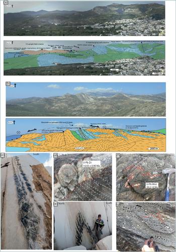
The Naxos core complex in the Cyclades Islands in the Aegean Sea (Figs 9, 10) is widely regarded as a Cordilleran-type core complex formed as a result of lithospheric extension (Lister et al. Reference Lister, Banga and Fenstra1984; Ring et al. Reference Ring, Glodny, Will and Thomson2010; Kruckenburg et al. Reference Kruckenburg, Vanderhaeghe, Ferré, Teyssier and Whitney2011; Rey et al. Reference Rey, Teyssier, Kruckenberg and Whitney2011). Although the whole Aegean Sea region is presently under lithospheric extension, possibly as a result of slab roll-back from the Hellenic subduction zone (Jolivet & Brun, Reference Jolivet and Brun2010), many islands preserve evidence for Late Cretaceous ophiolite obduction, and early Eocene (c. 52–46 Ma) subduction-related HP and UHP metamorphism (Fig. 11, stage 1) (Keiter et al. Reference Keiter, Piepjohn, Ballhaus, Lagos and Bode2004; Lagos et al. Reference Lagos, Scherer, Tomaschek, Münker, Keiter, Berndt and Ballhaus2007). The islands of Naxos and Ios also have spectacular examples of MCCs that show upright isoclinal folds and fabrics in kyanite- and sillimanite-grade gneisses and migmatites associated with crustal shortening and compression (Lamont et al. Reference Lamont, Searle, Roberts, Waters, Palin, Smye, Dyck, Gopon, Weller and St-Onge2019). These structures in the core of the Naxos dome are cut along the top by later low-angle extensional ductile shear zones and normal faults associated with (1) exhumation of ductile lower-crust rocks below the Koronos Shear Zone (Fig. 10a) and (2) later regional extension (Moutsana detachment; Fig. 9).
Geological map of Naxos Island and two cross-sections, one E–W and the other N–S, showing simplified geometry of the metamorphic core complex (after Lamont et al. Reference Lamont, Searle, Roberts, Waters, Palin, Smye, Dyck, Gopon, Weller and St-Onge2019). Note upright folds in the kyanite- and sillimanite-grade core unit truncated by the overlying Koronos Shear Zone, and folds and thrusts in the kyanite-grade Koronos Unit and retrogressed blueschists of the Zas Unit truncated by the overlying Moutsana detachment. NPDS – Naxos–Paros Detachment System.

Panorama and cross-section across Mount Koronos area, Naxos Island, showing the geometry of the folds, ductile shear zones and faults. (a) Infolded kyanite gneisses (green) and marbles (blue) of the Koronos Unit structurally overlying deepest-level kyanite- and sillimanite-migmatites of the core unit (orange) around Mt Koronos north of Filoti. (b) Upright axial planes of folds and fabrics in kyanite- and sillimanite-grade rocks (orange) and marble bands (blue) in the dome core are cut by the later low-angle Koronos Ductile Shear Zone; view north from Apano Kastro. (c) Vertical boudinage in amphibolite within marble indicating horizontal constriction in the centre of the migmatite dome, Mt Koronos. (d) S-type leucogranite on the eastern side of the migmatite dome, cross-cutting top-to-NE shear fabrics on the Koronos Shear Zone (KSZ) indicating shearing migrated up-structural-level with time. (e) Upright E–W-trending F3 fold shown by amphibolites in marble, elongated fabrics parallel to the fold axes, indicating N–S compression. (f) Prograde S2a and S2b crenulation cleavages in kyanite-grade gneisses from the Koronos Unit, implying syn-metamorphic shortening and compression. (g) Top-to-NE S-C fabrics in meta-granitoids on the Koronos Shear Zone overprinting earlier S2 crenulations and micro folds.

Tectonic model and simplified P–T–t paths for the formation of the Naxos metamorphic core complex due to compression. Stage 1: Attempted subduction of the leading edge of the Cycladic continental margin resulting in HP metamorphism of the Cycladic Blueschist Unit (including the Zas Unit). Stage 2: Continued shortening and underplating resulting in crustal thickening and Barrovian metamorphism (kyanite-grade metamorphism; Koronos Unit). Stage 3: Peak Barrovian metamorphism resulting in partial melting at the deepest structural levels. Stage 4: Return ductile flow and extrusion of migmatites and gneisses under the Koronos and Zas ductile shear zones, resulting in decompression and exhumation; note the continued underthrusting under regional compressional stress. Stage 5: Migmatite doming, horizontal constriction and folding of the Koronos and Zas shear zones. Stage 6: Switch to regional extension, exhumation and I-type granite intrusion. LANF – low-angle normal fault.

In Naxos and Syros islands an earlier HP eclogite–blueschist phase (c. 52–46 Ma; Tomaschek et al. Reference Tomaschek, Kennedy, Villa, Lagos and Ballhaus2002; Lagos et al. Reference Lagos, Scherer, Tomaschek, Münker, Keiter, Berndt and Ballhaus2007) was followed by a phase of crustal thickening and regional Barrovian metamorphism (c. 40–13 Ma; Fig. 11, stages 2 and 3) that shows a clockwise P–T path consistent with burial due to crustal shortening, and not regional extension (Lamont et al. Reference Lamont, Searle, Roberts, Waters, Palin, Smye, Dyck, Gopon, Weller and St-Onge2019). Continued compression and metamorphism culminated with partial melting during decompression, ductile flow and exhumation of c. 5–12 kbar kyanite- and sillimanite-grade rocks from depths of c. 25–45 km under a series of top-to-NE shear zones (Fig. 11, stage 4). U–Pb zircon ages from Naxos migmatites reveal that partial melting and formation of migmatites and S-type leucogranites occurred during the period 20.7–12.7 Ma (Keay et al. Reference Keay, Lister and Buick2001; Lamont T, PhD thesis, University of Oxford, 2018), whereas U–Pb monazite ages span the period 39–14 Ma and systematically show that metamorphism was diachronous, getting younger and of higher grade with structural depth. Anatexis first occurred by water-saturated melting, followed by fluid-absent dehydration melting as a result of isothermal decompression from peak-kyanite-grade conditions (Lamont et al. Reference Lamont, Searle, Roberts, Waters, Palin, Smye, Dyck, Gopon, Weller and St-Onge2019).
High-pressure rocks were exhumed from beneath lower-pressure rocks during exhumation, initially from a subduction zone setting and later from an orogenic channel-flow setting (Fig. 11, stages 1 and 4). The latter phase resulted in large jumps of P–T conditions across ductile shear zones that condensed a sequence of right-way-up isograds by the process of general shear (combination of pure shear and simple shear). These shear zones were active during 18.5–16.0 Ma and strongly resemble the STD shear zones in the Himalaya (Law et al. Reference Law, Searle and Simpson2004, Reference Law, Searle and Godin2006). Upon reaching mid-crustal conditions (5–6 kbar), the migmatite dome formed folding the top-to-NE shear zones. Inside the migmatite dome, constrictional fabrics are overprinted by later NE–SW extensional fabrics (Lamont et al. Reference Lamont, Searle, Roberts, Waters, Palin, Smye, Dyck, Gopon, Weller and St-Onge2019) (Fig. 11; stage 5). In Naxos, the switch from compression to NE–SW lithospheric extension occurred at c. 15 Ma when regional low-angle normal faulting (e.g. Moutsana detachment on Naxos) initiated, causing rapid cooling and exhumation of metamorphic rocks in the footwall (Fig. 11, stage 6). I-type granodiorite to monzogranite intrusions from Tinos, Mykonos and Naxos islands have U–Pb ages spanning 14.6–11.1 Ma (Keay et al. Reference Keay, Lister and Buick2001; Bolhar et al. Reference Bolhar, Ring and Allen2010). On Naxos, the low-angle normal-fault detachments and overlying Pliocene–Pleistocene sediments are folded around the core complex dome by post-peak metamorphic E–W compression. We suggest that the Naxos core complex was formed by compressional tectonics, folding, thrusting and high-grade metamorphism prior to regional extension across the Aegean Sea. Low-angle normal faults cannot have been responsible for exhuming kyanite- and sillimanite-grade rocks, and for uplifting these core rocks from depths of c. 30–40 km.
10. Discussion and conclusions
Although some metamorphic core complexes might be accounted for by lithospheric extension (extensional core complexes), a whole series of core complexes occur in compressional tectonic settings. Compressional core complexes show the following characteristics.
(1) High-grade metamorphic rocks are present in the dome cores, showing kyanite- and sillimanite-grade regional metamorphism, partial melting in the form of migmatites and tight to isoclinal folding. These rocks formed under compression at depth during crustal thickening and shortening, and are not related to lithospheric extension. As pointed out by Platt et al. (Reference Platt, Behr and Cooper2015), many core complexes show rocks exhumed from depths of 30–90 km, prior to formation of the detachment fault that presently overlies them.
(2) Exhumation of granulite (e.g. Ama Drime, Tibet) and eclogite facies rocks (e.g. Tso Morari, Ladakh Himalaya; As Sifah dome, Oman) or high-amphibolite-facies rocks in the cores of some domes (e.g. GHS domes, North Himalayan domes, Karakoram, Pamir and Naxos core complexes) cannot be explained by extensional flow from depths of c. 50–60 km. Instead, these rocks were brought up by low-level compressional thrusting and concomitant, high-level normal faulting during some sort of channel-flow process.
(3) The high-grade gneisses in the core are overlain successively by lower-grade and unmetamorphosed rocks along ductile shear zones and detachments that range from ductile to brittle and become younger towards higher structural levels. These detachments show extensional fabrics that formed during the exhumation of the deeper gneisses and migmatites beneath a passive roof stretching fault (Means, Reference Means1989), similar to the STD along the northern Himalaya.
(4) Structurally high, low-angle extensional faults in some MCCs (e.g. Naxos) developed later than compressional structures in the cores and cut upright folds, steep lineations and ductile fabrics in the high-grade gneisses in the core of the dome beneath (Lamont et al. Reference Lamont, Searle, Roberts, Waters, Palin, Smye, Dyck, Gopon, Weller and St-Onge2019).
(5) MCCs and low-angle normal faults do not necessarily equate to orogenic collapse (Dewey, Reference Dewey1988). The core complexes along the Himalaya, Karakoram and Pamir formed in a compressional tectonic regime during India–Asia convergence, a process that continues to this day. Thrust faults at depth bring these rocks upwards and low-angle normal faults bound their upper limit. The low-angle normal faults accommodate exhumation in the footwall, as the hanging-wall remained static. Pure-shear flattening concomitant with S-directed simple shear resulted in orogen-parallel extension and folding of the STD around the domes. Although the Aegean region probably does represent a collapsed orogenic belt now, metamorphic rocks in the Naxos and Ios compressional core complexes formed immediately prior to the initiation of regional extension during early Miocene time (c. 15 Ma).
(6) Little or no exhumation of these MCCs is driven by diapirism. Migmatization results in low-viscosity, lower-density rocks in the core, but the leucogranitic melts remain more-or-less in situ or intrude horizontally along the dominant schistosity (as seen throughout the Greater Himalaya) and do not intrude diapirically upwards. Exhumation occurred by foliation-parallel return flow and underplating of younger thrust sheets beneath, rather than diapirism.
(7) Isostatic rebound during extension cannot be the driving force to explain exhumation of 7–12 kbar kyanite- and sillimanite-grade metamorphic rocks in the dome cores. Regional crustal shortening and compression remains the dominant force causing metamorphism, with thrusting at depth, and low-angle normal faulting above. Partial melting triggered extrusion of the migmatite core rocks, as in the Greater Himalayan channel-flow model (Grujic et al. Reference Grujic, Hollister and Parrish2002; Searle et al. Reference Searle, Simpson, Law, Parrish and Waters2003, Reference Searle, Law, Jessup, Law, Searle and Godin2006, Reference Searle, Cottle, Streule and Waters2010; Law et al. Reference Law, Searle and Simpson2004, Reference Law, Searle and Godin2006, Reference Law, Jessup, Searle, Francsis, Waters and Cottle2011; Godin et al. Reference Godin, Grujic, Law, Searle, Law, Searle and Godin2006). Extensional fabrics along the upper contact were formed by exhumation of footwall rocks in a compressional environment.
(8) Climatic forces played an insignificant role in the exhumation of MCC rocks. Tectonic forces drive these crustal processes, and climate and erosion obediently follow. As mountains rise, erosion naturally increases. Nanga Parbat, the fastest exhuming and uplifting part of the Earth’s crust, lies in an environment that has been dry and arid throughout the last 3 Ma at least, and rainfall has played no part in its formation or uplift.
We suggest that the widely accepted definition of metamorphic core complexes (e.g. Teyssier & Whitney, Reference Teyssier and Whitney2002; Whitney et al. Reference Whitney, Teyssier, Rey and Buck2013) be amended to: “domal structures composed of ductiley deformed rocks and associated intrusions underlying a ductile-to-brittle high-strain zone that experienced tens of kilometres of relative normal sense displacement in response to lithospheric extension or compression”. We suggest that compressional core complexes are as common as extensional core complexes, if not more so, in the geological record and many core complexes previously attributed to lithospheric extension and isostatically driven uplift may need to be re-examined.
Author ORCIDs
Mike Searle 0000-0001-6904-6398
Acknowledgements
We gratefully acknowledge discussions in the field with Rick Law, Nick Roberts, Marc St-Onge, Owen Weller, Brendan Dyck and others, and thank John Platt for comments on an earlier version of the manuscript. TL acknowledges a Natural Environment Research Council (UK) PhD grant to work on Naxos.