

INTRODUCTION
The two early temples of Apollo on Temple Hill at CorinthFootnote 2 and of Poseidon at Isthmia,Footnote 3 dating from the first half of the seventh century, were the first in ancient Greece with a cella constructed of stone ashlar blocks squared on all six faces. This kind of masonry represents a crucial step in the development of Greek monumental stone architecture, marking a departure both from mudbrick construction, which had been the norm for most Greek buildings, and from previous experiments with stone construction. The blocks of the two temples were cut to uniform dimensions and arranged in a single row (as stretchers) in isodomic courses. As obvious as this technique might seem to a modern builder, when it emerged in these two sacred Corinthian sites it was unprecedented not only in Greece but indeed throughout the Ancient Mediterranean and the Near East, where previous stone masonries had usually consisted of a ‘double skin’ with inside and outside facing stones and rubble packing in between.Footnote 4
Hence the blocks from these two early temples offer a unique chance to understand the beginnings of Greek stone construction. Their most peculiar feature is the presence of two parallel grooves on each block's underside and on one lateral face. These cuttings have been explained, plausibly enough, as a way to move the blocks with ropes. Yet scholars disagree about how these ropes would have been used, and during what stage of construction. The earliest thesis, proposed by Saul Weinberg and endorsed by Oscar Broneer, suggested that the ropes would have served to lift each individual block into place and were subsequently extracted from the grooves once the block had been set against its neighbour.
Later scholars have dismissed this theory as both inconsistent with the evidence and technically impracticable, questioning whether lifting machines were used in Greek construction as early as the mid-seventh century; the widely accepted view holds that the crane appeared in the Greek world only at the end of the sixth century. As an alternative, they suggest that the grooves were cut early in the construction process so that ropes could be used to manoeuvre the blocks within the quarry. However, the ‘lifting’ theory continues to have its adherents.
Clarifying the significance of these parallel grooves is thus a matter of some importance to the history of Greek construction. In this article, I will reassess the alternative theses on the basis of a new examination of the evidence and demonstrate that the idea that the grooves served for lifting is the most plausible. Furthermore, I will argue that lifting machines appeared in Greece well before the late sixth century. The crane is regarded as one of the most remarkable Greek inventions in building technology. But when can a lifting machine be called a crane? In discussing lifting technologies, I will adopt the current definition of the ‘crane’ as an apparatus involving a rigid framework and one or more methods of mechanical gain (hoists, winches) to lift a heavy load attached to a rope, regardless of whether it can also move the load sideways, as certain cranes do.Footnote 5 I will refer to other, simpler devices as ‘lifting machines’ when they include some, but not all, of a crane's components. This distinction will allow us to ask at what stage Greek lifting machines became conceptually similar to modern cranes, and thus allow us to examine the nature of ancient Greeks' innovations in lifting technology. Finally, by examining how the blocks from Isthmia and Corinth would have been manoeuvred into place after lifting, it will contend that the grooves also served the purpose of placement, with a method that anticipates the sophisticated lever technique that spread during the Classical period.
The discussion is organised as follows. After a brief description of the blocks and their characteristic grooves, a chronological review of previous scholarship will focus on the various interpretations of these grooves and their purpose. The following sections will reassess the two alternative theses for their practical feasibility and their historical plausibility. Practical factors at play include the strength of the ropes presumably used by the ancient builders, the weight of the blocks, the depth and disposition of the grooves and the logistics of construction. Historical questions include deciding whether the ‘lifting’ theory necessarily entails use of a sophisticated apparatus like the crane, or can make do with more traditional devices. The next question is whether crane technology should be regarded as implausible at such an early stage of Greek history. To this end, I re-examine the earliest Archaic Greek blocks with cuttings that have tentatively been associated with lifting. Next, from a broad selection of ancient artefacts ranging from stone sarcophagi to ships, I discuss clues to potential forerunners of the crane, examining examples from the Bronze Age to the Early Archaic period, and from a wider context including Greece, the Eastern Mediterranean and the Near East. This article's last section analyses the grooves in relation to other features of the two temples' blocks, which have been overlooked in previous scholarship. These observations will shift the discourse from lifting to the next step in the construction process, which is the final setting of the blocks in place.
DESCRIPTION OF THE EVIDENCE
The blocks from the early temples at Corinth and Isthmia were not found in situ but scattered over the areas around the later temples.Footnote 6 With evident signs of fire damage, they were found mixed with burned debris containing fragments of terracotta roof-tiles, ceramics, votives and other materials that suggested a dating from the first half of the seventh century for both buildings. The presence of cult-related materials and the fact that the buildings were made of stone blocks and terracotta tiles suggest that these were monumental temples. At Isthmia, some of the blocks have been associated with sections of foundation trenches found below the floor of the Classical Temple of Poseidon. At Corinth, no clear traces of a predecessor to the sixth-century Temple of Apollo have been documented in situ on Temple Hill, but it is unlikely that the debris would have been brought up the hill from a lower level. Hence the material most likely belongs to an earlier temple on the same site.
The blocks from the two temples are similar in material, dimensions and shape. They are made from a soft and fine-grained oolitic limestone, which is different from the harder limestone used for the later temples in both locations.Footnote 7 This oolitic limestone was available in the immediate vicinity of both construction sites and was presumably quarried there. Complete blocks were found only at Isthmia. They measure approximately 0.27 m high, from 0.50 to 0.65 m wide – different widths presumably pointing to different walls of the cella – and, on average, a little more than 0.80 m long, although length is variable (Gebhard Reference Gebhard and Bietak2001, 47). At Corinth, blocks range from 0.205 to 0.245 m in height and from 0.70 to 0.78 m in length, and, while no single block preserves its full width, the maximum surviving width reported is 0.65 m (Robinson Reference Robinson1976a, 225–6).Footnote 8 At both sites, the blocks are believed to come from the cella walls, with the exception of two categories of blocks from Isthmia, which have been tentatively associated with a hypothetical peristyle.Footnote 9 Although none of the blocks exhibit proper band anathyrosis, on most of them the bottom was made roughly concave in the centre so that superimposed blocks made contact only over narrow bands at the front and back edges.Footnote 10 At Isthmia, one lateral joint face of each block was usually treated in the same way as the bottom. Tool marks show that the blocks were first roughly processed by adze or axe. Only the exposed faces, the upper surface and the contact edges were later finished with a chisel.
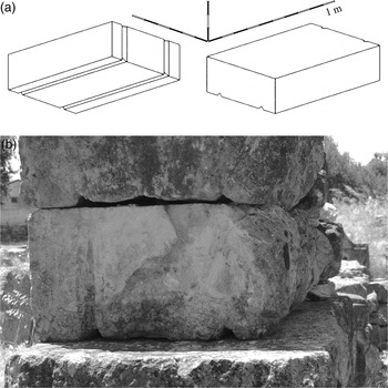
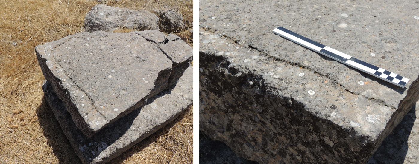
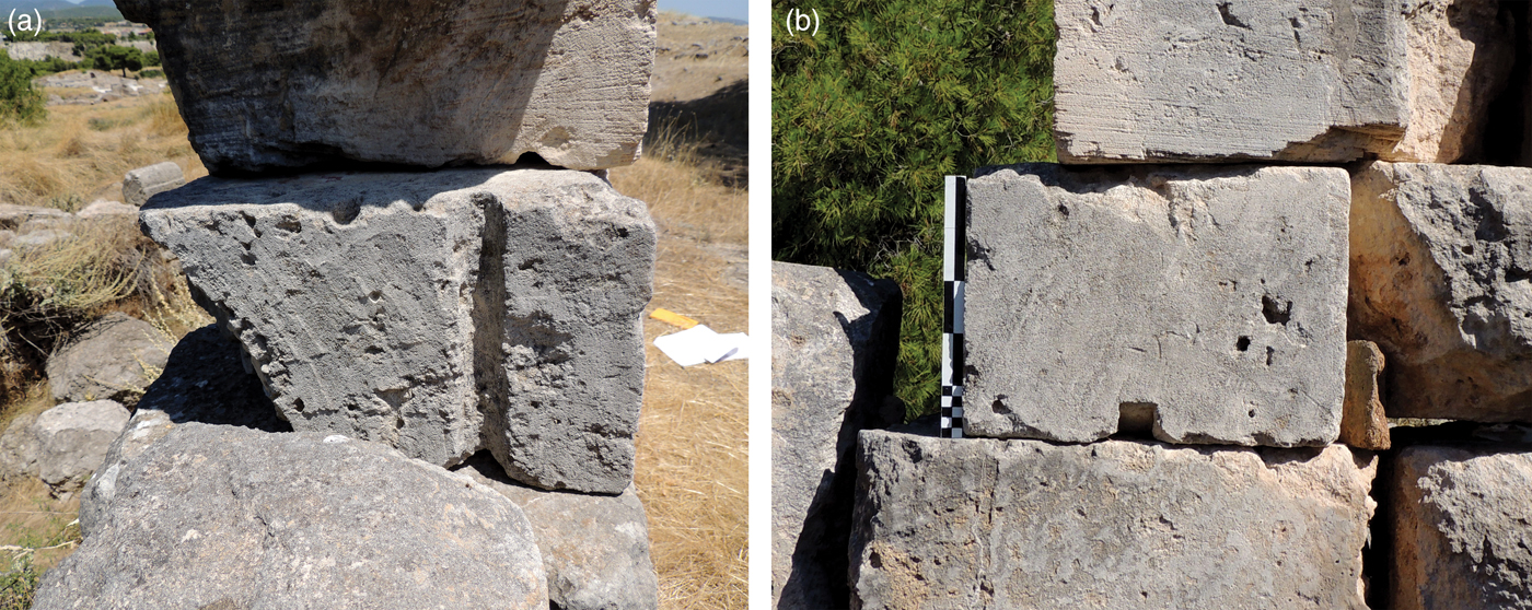
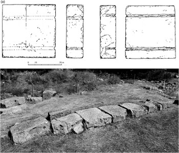
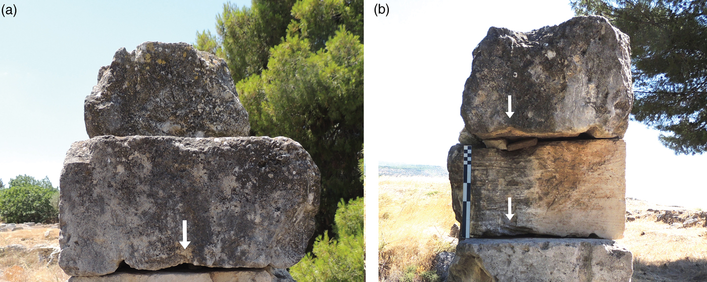
The two parallel grooves peculiar to the two temples' blocks are arranged along the bottom and usually continue up one end (Fig. 1), with few exceptions. The cuttings are set at approximately equal distances from the front and back edges – usually between 0.10 and 0.16 m. Most of the grooves have a triangular or pseudo-trapezoidal cross-section. They are usually about 0.02 m deep, and their width is in most cases about twice their depth. Tool marks suggest that they were carved with an adze and, in some cases, finished with a flat chisel.
(a) Typical disposition of the grooves on the bottom of a block and continuing along one end. (b) Grooves on the side of block Ar 20 from Isthmia. Drawing and photo by the author.

PREVIOUS SCHOLARSHIP
In 1938, Saul Weinberg found blocks that he attributed to a predecessor of the sixth-century temple on Temple Hill, at Corinth. Having observed grooves ‘encircling’ each of these blocks, he was the first to hypothesise that they ‘served to hold the ropes used in lifting the blocks into place’ (Weinberg Reference Weinberg1939, 595). In 1954, Mary Campbell Roebuck resumed the excavations at Corinth and found new evidence from the early temple. Based on the quantity of mud brick fragments found in the debris, she hypothesised that the building walls must have been made of this material and that the stone blocks belonged only to a wall-socle. For this reason, there would have been no need to lift them high enough to require a lifting apparatus. Roebuck proposed, instead, that the grooves served to lift the blocks out of the quarry or onto carts.Footnote 11
From 1952 to 1961, Oscar Broneer excavated the sanctuary of Poseidon at Isthmia and found hundreds of blocks with the same characteristic grooves, which he associated with an early temple and divided into categories on the basis of formal features. Unlike Roebuck, he restored the cella as a fully stone-built structure, assigning one category of blocks, shaped like a Doric geison, to the wall's upper courses. This reconstruction seemed to invalidate Roebuck's reason for rejecting the idea that the parallel grooves on the blocks were used in lifting, at least in relation to Isthmia. While Broneer did not directly discuss Roebuck's alternative thesis, his 1971 monograph on the Temple of Poseidon accepted Weinberg's original idea that the grooves were ‘intended to hold two ropes or cords by which the blocks were lifted and put into place’ and to let the ropes slip out once the block was laid with its two grooved faces in contact with the blocks already in place (Broneer Reference Broneer1971, 13).
In his 1975 review of Broneer's monograph, J. James Coulton (Reference Coulton1975, 271) questioned whether the lifting theory implied the use of a sophisticated lifting device as early as the first half of the seventh century. In his seminal essay of 1974, Coulton argued that use of cranes was not common in Greece until the late sixth century (Coulton Reference Coulton1974, 7). Indeed, the spread of tongs and lewis holes dates from this period, and both kinds of cuttings are generally accepted as positive evidence for the use of cranes. Following up this argument, Coulton presented a historical sequence showing that blocks weighing more than 20 tons were not unusual in buildings of the sixth century, supposedly lifted by means of ramps, whereas block size decreased from the end of the century. This reduction apparently occurred in conjunction with the introduction of cranes, whose loading capacity must have been initially limited. A related phenomenon was the disappearance of monolithic columns in favour of drum-built shafts at the end of the Archaic period, again a shift in technique presumably intended to keep the weight of individual blocks within the loading capacity of a crane. Coulton concluded that the sizes of individual blocks did not increase again until the Late Classical and Hellenistic periods, a development he linked to progress in crane technology.
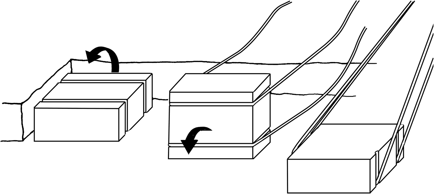
Henry S. Robinson and Charles K. Williams II excavated Temple Hill from 1968 to 1979. Robinson's report of the first five seasons, extending through 1972, mentioned vast quantities of stone fragments and furnished a synthetic description of certain types of blocks (Robinson Reference Robinson1976a, 224–31). He ascribed the mud brick found in the debris not to the temple itself, but to the north wall of the Archaic roadway, on which the temple's remains had subsequently been dumped. Consequently, in contrast to Roebuck's previous hypothesis, he restored the temple with a cella wall constructed of stone blocks from foundations to eaves, and accepted the idea that the grooves on the individual blocks served to provide a hold for lifting ropes (Robinson Reference Robinson1976a, 227) (Fig. 2).
Grooves and ropes as devices for lifting, attached to cranes. Drawing by the author, after Robinson Reference Robinson1976a, 226 fig. 7.

In subsequent years, the materials from the two temples were re-examined by Robin F. Rhodes, who later took over the study of the early temple at Corinth.Footnote 12 Rhodes's conjectural temple reconstruction considered both options for the cella: a fully stone-built wall or a stone socle with a mud brick superstructure (Rhodes Reference Rhodes, Williams and Bookidis2003, 88), and for both alternatives he restored a stone cornice at the top of the wall, basing his hypothesis on a set of blocks cut to receive roof beams. In contrast to Robinson's view, Rhodes contested the idea that the parallel grooves on the cella blocks could have served for lifting (Rhodes Reference Rhodes1984, 27–9; Rhodes Reference Rhodes1987c). On the one hand, he questioned practical aspects of the operation. The grooves, to his mind, were too shallow to accommodate ropes thick enough to lift an individual block, and yet slender enough to be pulled free once the block had been set in place. Furthermore, the ropes used in lifting should have produced friction marks on the blocks, but the extant blocks from the two temples show no such marks.
On the other hand, Rhodes noted certain Isthmian blocks with unusual features he found inconsistent with the theory that the parallel grooves were used in the final process of laying down the blocks and removing the ropes (Rhodes Reference Rhodes1987c, 548). Firstly, one block (Ar 17) only has grooves on the underside and none on either end. Broneer had suggested that this element must have been ‘designed for the first stone set down in a given course’ (Broneer Reference Broneer1971, 15). Because no other block had been set next to it, there was no need for grooves on its end to extract the lifting ropes; they would simply fall away. Rhodes countered that, if the later Greek practice of building walls by beginning with the corners was already in use in this period,Footnote 13 Ar 17 could not possibly have been the first laid in its course, for this block has edge anathyrosis on both ends and could not have served as a corner block (Rhodes Reference Rhodes1987c, 548). Secondly, two blocks (Ar 14, 15) present two mutually perpendicular pairs of grooves on the underside. Pulling out either of the perpendicular ropes would have been impossible because it would have been pinched between the other and the stone surface underneath (Rhodes Reference Rhodes1987c, 549). Lastly, in describing another, unusually short (0.369m) block (Ar 39), Broneer proposed that it must be the last one laid down in its course, trimmed to fit precisely into the void left between the blocks already in place (Broneer Reference Broneer1971, 25). But the disposition of the grooves, as usual on the bottom and on one end, is once again problematic, for the ropes would have been pinched between the non-grooved end of Ar 39 and the adjacent block.
Having rejected the lifting theory, Rhodes (Reference Rhodes1987c, 550–1) elaborated on Roebuck's idea that the grooves might have served to remove the blocks from the quarry. He suggested a process in which, after three sides of a block were freed (as usual, by digging trenches around each individual block), grooves were immediately cut on the front and top surfaces. Then, after the block was detached from the quarry bed, it was tipped onto its side and tipped over again, using ropes to ease it down (Fig. 3). The grooves were cut to prevent the ropes from slipping off the block while it was being moved; and with the channels cut in advance, the ropes could be put in position and the block readied for removal from the quarry as soon as it had been turned.
Grooves as devices for removing the blocks from the quarry. Drawing by the author, after Rhodes Reference Rhodes1987c, 551 fig. 5.

Recently, however, Frederick P. Hemans (Reference Hemans, Gebhard and Gregory2015, 45–9), who conducted excavations at Isthmia with Elizabeth R. Gebhard in 1989, has reaffirmed the lifting theory. Without discussing Rhodes's alternative explanation for the grooves, Hemans briefly addresses one of the practical objections to lifting, namely whether the grooves are compatible with ropes strong enough to lift the blocks. On this subject, he notes that ‘while there are a very few examples of blocks that would not have accommodated a 0.01 m rope, these are rare among the hundreds of blocks' (Hemans Reference Hemans, Gebhard and Gregory2015, 47). He also reports that a modern sisal nautical rope 0.01 m thick has a breaking load of c. 400 kg, equal to the estimated weight of the heaviest blocks at Corinth and Isthmia. Considering that each block potentially accommodated two ropes, he concludes that loading capacity would have been about twice as much as needed.
In addition, Hemans interprets two factors in connection with the idea that cranes were used at Isthmia. First, some of the blocks from the early temple have U-shaped channels on their underside, in addition to, or instead of, the usual parallel grooves. Based on the function of U-shaped channels in later contexts, Hemans interprets this trait as decisive evidence for the use of cranes. Second, five longitudinal rows of circular holes are found in the ground below the level of the early temple's original floor. While Broneer, who found the holes, associated them with scaffolding, Hemans (Reference Hemans, Gebhard and Gregory2015, 49) suggests that they ‘mark the positions of hoists or cranes that were used to erect the walls'. He concludes that the early temple's blocks were lifted by a single-arm crane that hoisted them directly to their final place in the wall.
The continuing scholarly debate about the purpose of the grooves calls for a detailed reassessment of the alternative theses. As we have seen, Roebuck's argument against the lifting theory has been disproved at both sites by the existence of blocks from the top of the cella walls, which did need lifting. As yet, however, the idea that the grooves were used in the quarry has neither been critiqued nor dismissed. Rhodes's objections to the lifting theory demand a more complete and detailed discussion. Finally, Hemans's arguments in favour of crane use must be re-examined, along with potential alternatives, in relation to the historical problem of lifting technologies' early development.
WERE GROOVES USED IN THE QUARRY?
Re-examination of the quarry theory reveals several problems. A first issue regards the fact that Broneer's excavations of the gully north of the temple at Isthmia produced several presumably unused blocks. Two of these had grooves, while others did not and were only partially finished (Broneer Reference Broneer1971, 15). The presence on the site of blocks without grooves from the early temple would prove that a) the grooves were not cut in the quarry, and b) were not actually needed before the blocks were employed in the masonry. Unfortunately, however, these blocks are now lost and their association with the early temple can no longer be proven. Consequently, while Broneer's account casts doubt on the theory here examined, his evidence cannot be regarded as conclusive.
Another critical point regarding this thesis is the lack of positive evidence or parallels to support it. In fact, to my knowledge, no quarries, either before or after this period, preserve abandoned blocks with comparable grooves. It is particularly difficult to study early quarry techniques because later operations obliterate previous evidence. However, evidence suggests that from the Bronze Age, the same basic method had been used throughout the ancient Mediterranean with all types of stone, both soft and hard: that is, by digging a trench around the perimeter of each block and then detaching its bottom with wedges (Shaw Reference Shaw2009, 30). The only traces that this method usually leaves on the blocks themselves, before they are turned with a crowbar and given a first finish, are horizontal striations on the sides, produced when the trench is dug with a pickaxe or a similar tool, and channels resulting from chisel-cut holes, often used to accommodate wedges.Footnote 14 These channels are different from the parallel grooves on our blocks, for they do not usually run the whole length of a block's face and they occur as a row of several short elements approximately 0.10–0.20 m apart.
From a practical standpoint, quarrying operations do not provide a compelling explanation for the disposition of the grooves in any case. Rhodes illustrates a quarrying process that requires only the grooves on the horizontal face of the blocks; there is no need to carve vertical channels on the lateral face. Moreover, once a block had been detached from the bedrock, the ropes in the horizontal grooves could not help in turning or lifting it, manoeuvres necessarily carried out by means of levers, but were only used to ease it down and drag it.
As for dragging the blocks in the quarry (presumably on wooden tracks, rollers, or on a sledge, in order to reduce friction), the ropes could be secured well enough by carving two small notches at the edge of their undersides; the grooves would have been an unnecessary precaution. The Corinthians seem to have adopted this simple method to secure the ropes for moving their stone sarcophagi. These monoliths had been provided with notches in the middle of their exterior vertical edges ever since the Middle Geometric period,Footnote 15 and the sarcophagi on display in the Archaeological Museum at Ancient Corinth show that the same method was still in use around the mid-seventh century.
In brief, even without considering Broneer's report of blocks without grooves found on the construction site, there is no evidence to support the idea that the grooves were carved in the quarry to facilitate operations in that setting.
PRACTICAL ASPECTS OF THE LIFTING THEORY
We must now re-examine Rhodes's objections to the lifting theory, beginning with the practical question of whether the grooves are deep enough to accommodate ropes of a sufficient strength to support an individual block. To this end, we must consider groove depths in relation to rope thickness and strength, and in relation to the maximum weight of the blocks. Hemans briefly dismissed this problem by stating that most grooves at Isthmia are deeper than necessary to accommodate robust ropes, but we must focus on minimum depth values to eliminate any rare exceptions that could undermine the theory. In addition to expanding on Hemans's data from Isthmia, we must also widen the scope of our inquiry to include the blocks from Corinth, research on which has yet to be published. Moreover, Hemans's conclusions refer to a modern sisal rope, whereas an accurate assessment must take into account the kinds of ropes used by the ancient builders. In conclusion, I will investigate whether lifting ropes could have produced friction marks on the blocks, and examine the practical feasibility of extracting the ropes.
Minimum groove depthsFootnote 16
Because of their rough manufacture, the grooves vary in depth along their length. To record the minimum values, whenever possible, I took measurements by sliding a ruler along the bottom of each groove and using a board laid against the surface, across the groove, as a reference. Grooves on the same face of a block usually run at about the same depth, while those on the same block but on different surfaces (horizontal v. vertical) sometimes differ in depth. My measurements aimed at recording the minimum depth value for each block, though this operation is complicated by the fact that the grooved surfaces usually have edge anathyrosis. Consequently, in order to estimate the total width of the gap that would have been left for a rope to be pulled out, a block fragment has to be large enough to preserve both a groove and its adjoining contact surfaces.
At Corinth, of the 417 fragments mentioned in Robinson's report (Reference Robinson1976a, 224), about 100 are large enough to supply useful information.Footnote 17 It is possible to measure minimum groove depths with sufficient accuracy on 54 of these. I did not observe a depth less than 0.01 m (Rhodes reported a minimum depth of 0.007 m), a figure that occurs only in one vertical incomplete groove on block 165.Footnote 18 Apart from this exceptional example, the minimum figure is 0.012 m, which occurs in blocks 304 (depth 0.012 m, width 0.030 m) and 208 (depth 0.012, width 0.027 m).Footnote 19 Minimum depth values can be described as follows, by adopting ranges of depth variation of 0.005 m:
Class 1, depth smaller than 0.012 m, consisting of 1 element
Class 2, depth 0.012–0.017 m, consisting of 12 elementsFootnote 20
Class 3, depth 0.018–0.023 m, consisting of 27 elementsFootnote 21
Class 4, depth 0.024–0.029 m, consisting of 9 elementsFootnote 22
Class 5, depth larger than 0.029 m (maximum depth 0.037 m), consisting of 5 elements.Footnote 23
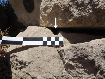
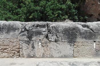
At Isthmia, Broneer used most of the best preserved stone materials from the temple to reconstruct a portion of the cella wall. It is possible to access the grooves on only some of these, and only at some points along their length. I was therefore able to take measurements in the way described above with only about 10 per cent of the blocks.Footnote 24 As a result, my data from Isthmia are less exhaustive than those from Corinth, and I will confine myself to reporting the minimum value and the interval of maximum frequency. Beginning with the latter, my survey confirms that most grooves have depths between 0.02 and 0.03 m, as previously reported by Hemans (Reference Hemans, Gebhard and Gregory2015, 45). The minimum value, however, is 0.011 m. Interestingly, the corresponding groove is not on a bottom or side face but on the exposed overhanging soffit of one of the geison blocks (Ar 70, Fig. 4), where extracting the ropes would not have posed problems. Furthermore, the smooth surface around the groove might suggest that, in this case, the groove was initially deeper but was reduced when the surface was finished, after the block was set in place.
Block Ar 70 from Isthmia (the block is upside down, so the groove faces upwards). Photo by the author.

Maximum weight of the blocks
The average weights of the ordinary cella blocks from Corinth and Isthmia are 185–211 kg and 224–256 kg, respectively, but some blocks from Isthmia are much heavier than this.Footnote 25 To estimate their maximum weight, I have considered the geison blocks from Isthmia (Fig. 5),Footnote 26 whose average size is about 0.27 × 0.90 × 0.80 m = 0.1944 m3. Because the volume of these blocks is reduced by their peculiar cut on the underside, this figure should be rounded down to about 0.180 m3. Assuming a density value for Corinthian oolitic limestone of 1.75–2.00 tons/m3,Footnote 27 the corresponding weight must lie within the range of 317–362 kg.
Geison blocks (group 10) from Isthmia, piled at the west end of Broneer's reconstructed wall. Photo by the author.

Ancient ropes: plant fibres and rope strength
Ancient Greek and Latin literary sources mention seven plants in connection with ropemaking: papyrus, from Egypt; flax, cultivated in Egypt and in other regions of the Eastern Mediterranean, including Greece; hemp, grown in Italy and in the Rhone valley; esparto, from the Iberian Peninsula; date palm, widespread in Egypt and in general in the south-south-east of the Mediterranean; broom, endemic in most of the Mediterranean coastal areas; and rush, present in Greece (Casson Reference Casson1971, 231; Charlton Reference Charlton1996, 16–36, 115–16).
Field research has provided physical evidence for five of these fibres: ropes of esparto, hemp, palm and rush have been found in shipwrecks,Footnote 28 while papyrus is associated with contexts in the Egyptian mainland.Footnote 29 In addition to the plant fibres known from literary sources, there is physical evidence of ropes made from halfa grassFootnote 30 (a poaceous plant widespread in Africa and the Middle East), doum palm and common reed.Footnote 31
Pliny the Elder (19.8.29) singles out ropes of esparto (Stipa tenacissima) for being among the strongest ones suitable for nautical and construction use.Footnote 32 Esparto was certainly used in Greece, but only after 237, when the Carthaginians invaded Spain, its area of production, after which esparto was exported throughout the Mediterranean.Footnote 33 One of the ancient Latin names for esparto, spartum, could also refer to a native Greek plant that had been used to make rope from Homeric times; thus in the Iliad (2.135), spartos can mean either the plant itself, or ‘rope’. This plant is broom (Spartium junceum), endemic to the region of Thebes in Boeotia.Footnote 34
From very early times, flax (Linum usitatissimum) had also been used to make cordage in Greece. In antiquity, flax ropes were well-known for their extraordinary strength, mentioned by Pliny (37.77.202–3), along with esparto, as some of the most valuable commodities of his time. Herodotus (7.25.1, 34.1, 36.3) recounts that Xerxes, during his military campaign against Greece in 480, commissioned ropes of white flax from the Phoenicians, and ropes of papyrus from the Egyptians, to build bridges across the Hellespont. A line from Euripides confirms the use of flax in Greek rope manufacture during the Classical period (Casson Reference Casson1971, 231 n. 27; Charlton Reference Charlton1996, 20–1). Its use for the same purpose presumably dates as far back as the Mycenaean period, as suggested by Linear B sources which state that the city of Pylos was renowned both for the cultivation of flax and the manufacture of ropes.Footnote 35
In summary, the earliest Greek literary references to ropes suggest that flax and broom were used in Greece for rope making from pre-Archaic times. Use of flax ropes, in particular, is also attested in Greece in the Classical period and later. While there is no direct evidence for flax ropes from early-seventh-century Corinthia, it is nonetheless plausible that in this period, too, the Corinthians, with their advanced nautical industry, would have had access to ropes of this material or of other fibres of comparable quality, as strong ropes are essential in nautical technology.Footnote 36
Vegetable fibre ropes have high tensile strength, and the analysis of archaeological samples shows that the quality of ancient Egyptian, Greek and Roman cordage was as high as that of similar modern products.Footnote 37 The breaking load of traditional flax rope 0.01 m in diameter exceeds 750 kg, and that of a rope 0.008 m in diameter is almost 500 kg, more than enough to lift the heaviest of the Early Archaic blocks from Isthmia and Corinth.Footnote 38
The question of whether ropes of small diameter were common in antiquity finds a partial answer in nautical archaeology. Although the evidence provided by wrecks and other findings of nautical cordage is patchy, ropes about 0.01 m thick, or less, are documented from Eastern Mediterranean contexts dating from the Bronze Age and from the Late Classical and Early Hellenistic periods (Charlton Reference Charlton1996, 55–71). Ultimately, the data examined thus far support the thesis that the blocks were lifted by ropes. Indeed, the grooves are carved to a depth that will admit ropes thick and strong enough to sustain even the heaviest load.
Friction marks
Rhodes's next argument against the lifting theory rests on the hypothesis that lifting by ropes would have produced friction marks on the blocks, whereas no such marks are visible on the extant blocks. He bases his argument on an experiment conducted at Nemea during the first phase of the Temple of Zeus Reconstruction Project (1980–3), where the original blocks from the Archaic temple were lifted by means of nautical ropes measuring less than 0.01 m in diameter, producing relatively deep marks on the surface of the stone.Footnote 39 Rhodes provides no detailed description of this experiment; hence my own considerations must rely to some extent on hypothesis. Theoretically, the act of lifting should not necessarily induce ropes to slip along the stone surface. Yet we can imagine that tension in the ropes, possibly associated with slight oscillations of the hanging block, might have turned the sharp upper edge of the non-grooved side face into a sensitive point, especially considering the softness of the freshly cut oolitic limestone. As a result, we might surmise that slight abrasions could have been produced on this edge and therefore appear on the original blocks. However, one additional consideration points to a different conclusion.
According to a Greek building practice common from the Archaic period onwards, blocks were quarried at a slightly larger scale than their anticipated final dimensions and were transported to the construction site with this extra layer of stone (àpergon; Martin Reference Martin1965, 199) still in place. Their extra height accommodated any irregular fracturing that might occur when the block was separated from bedrock.Footnote 40 Moreover, the excess layer of stone around a block would have protected it from accidental damage during transportation. Lastly, it would have allowed masons to achieve uniformly level surfaces by giving walls and other architectural elements their final finish only after all the blocks had been set in their final position. The use of this method in pre-Archaic construction is suggested by the remains of a layer of stone projecting c. 0.02 m above the finished surface of a faceted drum from the Geometric period recovered from well 72–2 at Corinth (Rhodes Reference Rhodes1987b, 230; Brookes Reference Brookes1981, 288). The excavations at Isthmia likewise provide evidence that this practice was observed in the construction of the early temple.Footnote 41 Indeed, on the exposed surface of three blocks,Footnote 42 the protective excess layer of stone was only partially removed, beginning, as usual, from the edges (Fig. 6).
Block Ar 9 from Isthmia, with upper surface left unfinished. Photos by the author.

Following this practice, a block arriving at the construction site ready for use would have had only two of its faces finished before it was lifted into place. These finished faces would have been the bottom and the end intended to make contact with the neighbouring block already in place – in this case, the grooved end. The top and the opposite end of the block would still be covered in their protective stone skin during lifting. Consequently, if the ropes had produced friction marks on the top edge of this end, these marks would likely have been effaced when the protective skin was removed, after setting the block in place.
Extracting the ropes
Once it has been established that the grooves are compatible with ropes strong enough to support an individual block, and that the absence of friction marks does not necessarily undermine the lifting theory, it remains to show that the ropes used in lifting could be pulled from their grooves easily, without damage either to the rope itself or to the block. Traditional ropes made from plant fibres are coarse and less flexible than modern synthetic products, suggesting that the grooves' rough manufacture and their 90-degree turn at the end of each block may have presented problems, especially given the high friction coefficient of oolitic limestone.
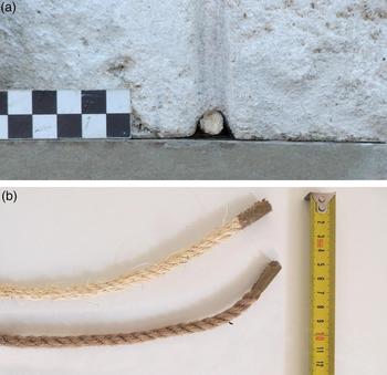
I therefore carried out experimental tests on a replica block made from oolitic limestone of the same quality as that of the original blocks (Fig. 7a), squared by adze and finished by chisel.Footnote 43 I based its final dimensions (0.27 × 0.55 × 0.80 m) on the average measure of the blocks from Isthmia. Three grooves of different depths were carved on the underside and on one end of the block. Tool marks in the grooves were not smoothed, but left as rough as they appear on most original blocks. For the extraction test I used single lines of traditional broom and flax ropes without knots (Fig. 7b).Footnote 44 In deciding on rope thickness and groove depth, I examined the worst case scenario presented by the data discussed in the previous sections of this article, and managed to slip a rope 0.008 m thick out of a groove 0.01 m deep and 0.015 m wide. While the 90-degree angle slowed down the process to some degree,Footnote 45 the operation, which was repeated 10 times, proved to be relatively effortless and neither damaged the rope nor produced visible marks on the stone.Footnote 46 The experiment yielded similar results when repeated with the other two grooves, with depths of 0.012 and 0.015 m (groove width being approximately twice as large), and ropes with diameters of 0.010 and 0.012 m, respectively. In the replica, as well as in all of the well-preserved blocks observable, the hollowing of the two grooved faces (which is maximum at the face's centre) is imperceptible or very small at each groove's sides. Consequently, the ropes could not deviate sideways from their trajectory and never got jammed while being pulled out.
(a) Replica block with a groove 0.012 m deep accommodating a 0.010 m thick rope. (b) Broom (top) and flax (bottom) traditional ropes 0.008 m thick. Photos by the author.

GROOVES IN UNUSUAL DISPOSITIONS
We now turn to Rhodes's objections relating to unusual features of some Isthmian blocks. These features present apparent inconsistencies with the second step of the lifting theory, that is, laying down the blocks and extracting the ropes. Rhodes begins with the block that displays grooves on its bottom but not on its ends (Ar 17). Because this block has edge anathyrosis on both ends, we must agree with Rhodes that it could not have been from a corner. If corner blocks were the first in their course to be laid, then Broneer's argument that Ar 17 had no grooves because it was laid first cannot hold.
The idea that corner blocks were laid before their neighbours seems consistent with the fact that the only well-preserved corner block from Isthmia (Ar 41) has no vertical grooves on its sides. Moreover, there were practical advantages to beginning construction at the two ends of a wall. In the first place, it would have been difficult to manoeuvre a corner block into place if its neighbour had already been set; without a free horizontal surface available on the bedding there was no way to lever the corner block into its place.Footnote 47 Secondly, starting construction from the corners would have allowed a single lifting device placed opposite the middle of the wall to supply two teams of masons working simultaneously (Coulton Reference Coulton1974, 5 n. 26). We should thus agree that block Ar 17 was likely not the first to be laid in its course. Yet does this fact necessarily weaken the argument that grooves served to lay down the blocks and then remove the ropes?
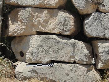
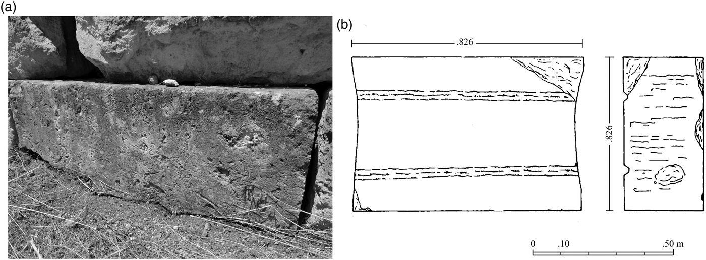
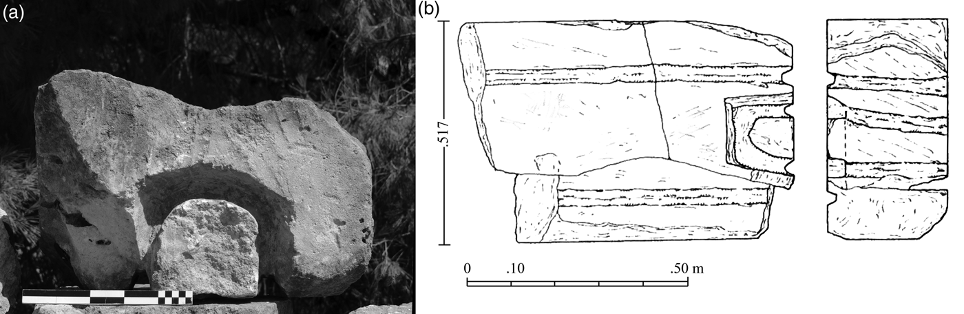
Direct examination of Ar 17 is problematic because it lies at the base of Broneer's rebuilt wall, with adjacent blocks hiding its ends (Fig. 8a). However, the published drawing (Broneer Reference Broneer1971, 18 fig. 8) shows that the edge anathyrosis on its ends is much deeper than the other blocks', such that it would have been easy to extract ropes from the gap left between this block and its neighbour (Fig. 8b).Footnote 48 Therefore, the absence of vertical grooves on this block does not undermine the theory here examined, although it remains to be explained why in this case the builders achieved the same result by using the anathyrosis gap instead of the usual end grooves. It is worth remembering, however, that the blocks from these two early temples show the earliest known occurrence of anathyrosis, and that the resulting masonry represents a first primitive step toward opus isodomum. Masons must have developed the necessary know-how and craftsmanship experimentally at the same time as building progressed. Given the experimental nature of Early Archaic Corinthian stone construction, some lack of consistency must be expected, all the more so because constructing stone-block buildings required a larger number of workers, and more complex coordination, than building mud brick and timber structures.
Block Ar 17 from the early temple at Isthmia. (a) Photo by the author. (b) Drawing by the author, after Broneer Reference Broneer1971, 18 fig. 8.

In the case of the blocks displaying two pairs of mutually orthogonal grooves on the underside, Rhodes (Reference Rhodes1987c, 549) contended that it would have been impossible to use four ropes simultaneously and then remove them from the grooves, unless two of the grooves were significantly deeper than the others. My survey shows that in both blocks of this category the orthogonal grooves do, in fact, have different depths, c. 0.030 and 0.016–0.020 m, respectively (Fig. 9).Footnote 49 The existence of similar blocks among the finds from the Corinth temple might be suggested by two mutually perpendicular grooves on fragment 276. In this case, too, the orthogonal grooves have different depths (0.02 and 0.03 m, respectively).Footnote 50
Block Ar 14 from Isthmia, with crisscrossing grooves. Photos by the author.

The third problematic case Rhodes presents is that of the short block Ar 39 (Fig. 10). Broneer suggested that this was the last to be laid down in its course. This hypothesis, however, seems inconsistent with the disposition of grooves on the bottom and on one end of the block, because the rope projecting from the non-grooved end would have prevented it from slotting into its gap. It is therefore worth exploring two alternative scenarios: first, Ar 39 might not have been laid down with ropes, or second, it might not have been the last one placed in its course. As for the first option, it must be noted that, among all the stone materials from the two early temples at Isthmia and Corinth, Ar 39 is the only block that features what seems to be a shifting notchFootnote 51 at the exposed face's bottom edge (Fig. 10b); this feature might suggest that the builders were experimenting with alternative techniques for manoeuvring the last block into its gap from the front.Footnote 52
Block Ar 39 from Isthmia, side (a) and front (b) views. Photos by the author.

As for the block's order of placement, it is true that in Greek stone-block masonry, because the courses were usually laid from the corners of the wall toward the centre, a block of non-standard length might potentially be required in the middle of a course in order to complete it.Footnote 53 However, short blocks would not necessarily have served only this purpose. Indeed, trimming down a course's final block from one of average size would have produced another short block as scrap. We can imagine that such short blocks might have been put aside to be used in the same way on other courses. Yet not all of these scrap blocks would necessarily have been long enough to fill any final gap, in which case I believe they would have been used at other points of the masonry. After all, short blocks such as Ar 39 would also have been needed at different points of the wall in order to break the continuity of vertical joints between successive courses.
Nor did the block cut to fit the final gap in a course necessarily have to be unusually short. The length of the Isthmian blocks is variable, so that in some cases the final gap could be filled by a block of average length. Such a conclusion is consistent with the presence, at Isthmia, of both short and average length blocks with grooves on the bottom and on both ends.Footnote 54 According to Broneer (Reference Broneer1971, 14), these too were designed to fit into the last gap on their courses. In this case, the disposition of the grooves is consistent with Broneer's hypothesis, for it would have allowed the builders to insert the last block into its gap and remove the ropes.
Rhodes's alternative explanation for the grooves on both ends of these blocks seems less convincing. He suggests that these were the last blocks on a given bedding plane of the quarry, removed by two sets of workmen quarrying in opposite directions. It is unclear, however, why both crews would have cut the blocks' grooves on opposite ends. Even assuming that Rhodes is correct, in fact, these blocks would have been tipped out on one side, not both.Footnote 55
On the basis of these reflections, we can conclude that neither the length of Ar 39 nor the aforementioned blocks' unusual disposition of grooves necessarily weakens the theory that the grooves were used in the final process of laying down the blocks on their course and removing the ropes. More generally, none of the objections examined thus far seem to undermine the lifting theory. On the contrary, this theory provides a more compelling account of the grooves and their disposition than its alternative. Does it also imply that cranes were used in Greece as early as the first half of the seventh century?
EARLY LIFTING TECHNOLOGIES
While the grooves were most plausibly cut on site and used in lifting the blocks by means of ropes, this is not enough evidence for claiming that the builders were employing cranes. Before exploring the hypothesis that these sophisticated lifting machines were used at such an early stage of Greek construction, we must examine more traditional low-tech alternatives in light of the evidence from the two temples.
Low-technology alternatives to the crane and the evidence in situ at Isthmia
The earliest method used by all ancient civilisations for lifting heavy objects was pulling them by ropes up ramps made of earth or mud brick.Footnote 56 From a mechanical viewpoint, the ramp is an advantageous machine: lifting an object on an inclined plane requires less force than lifting it vertically, at a cost of an increase in the distance the object must be moved. Therefore, the longer the ramp (and the lower its pitch), the greater the advantage in using it. On the one hand, the ramp allows the lifting of loads of virtually unlimited size without conceptual or practical complications, so long as the ramp itself is large and solid enough to support the load. On the other hand, ramps of soil or mud brick require a considerable expenditure of effort for construction and removal, regardless of the size of the blocks being lifted. Therefore, we would generally tend to associate them with sizable loads. As a matter of fact, earthen ramps and scaffolds were the main means of lifting stones and carrying them to their final place in the masonry in Pharaonic EgyptFootnote 57 and Assyria.Footnote 58 In these regions, the use of blocks weighing several tons was common in monumental construction, and a plentiful supply of labour was available for building and removing massive earth structures.
The same method is believed to have been the norm in the Greek world throughout the Archaic period, so a reasonable conjecture would be that the Early Archaic blocks from Corinth and Isthmia were lifted in this way.Footnote 59 As documented outside Greece, a common system to reduce friction while moving blocks along a track was to arrange them on wooden sleds.Footnote 60 Yet this method would fail to explain the presence of grooves on our blocks, because the ropes would be fastened to the sled, not to the blocks.
Alternatively, we can imagine that, accommodated by the grooves, the ropes could have served to suspend the blocks from a sling carried by hand up a ramp and along an earthen scaffold. However, two considerations cast doubt on this hypothesis. The first is purely practical: the blocks from the two early temples are of modest size compared with the average loads lifted by ramps in Egypt and Assyria, or with the Greek blocks presumably lifted the same way in the following decades of the Archaic period.Footnote 61 Consequently, the idea of going to the trouble of building and dismantling earthen structures might not have appeared very practical, and might have encouraged the use of alternative methods, if available.
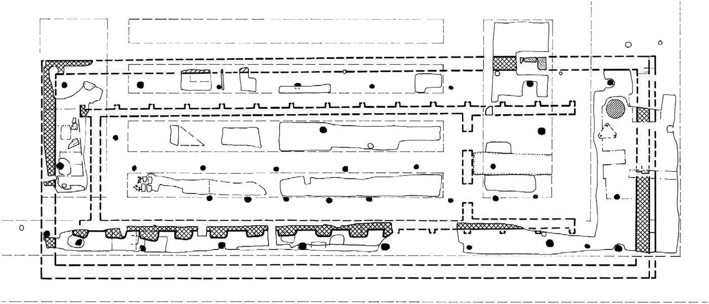
The next consideration concerns the five rows of circular holes Broneer found below the floor level of the early temple at Isthmia (Fig. 11). These holes reach diameters up to 0.46 m and depths of up to 1 m below the original floor level, and their spacing changes from row to row, with 5 m being the most common.Footnote 62 The location of the rows, which are set on either side of the presumed position of the cella walls and along the centre axis of the building, suggests that the holes accommodated wooden structures somehow related to the construction of the early temple.Footnote 63 If so, then these structures were set where we would have expected earth scaffolds, suggesting that the latter were not used.Footnote 64
Conjectural reconstruction of the plan of the early temple at Isthmia, showing the circular holes (in black) presumably associated with the construction of the building. Drawing by the author, after Hemans Reference Hemans, Gebhard and Gregory2015, 42 fig. 3.2.

An alternative low-technology hypothesis based on the relatively moderate weight of the two temples' blocks is that they could have been ‘passed from one pair of men to the next up a stepped wooden scaffold’ (Rhodes Reference Rhodes1987c, 551 n. 41).Footnote 65 While this idea is consistent with Broneer's initial association of the holes with scaffolding (Broneer Reference Broneer1971, 11), I believe it unlikely that the geison blocks from this site, weighing up to about 360 kg, could have been lifted this way. Even with teams of four porters,Footnote 66 passing a block from step to step multiple times would have been time-consuming and hardly practical.
Finally, in his most recent contribution to the debate, Hemans (Reference Hemans, Gebhard and Gregory2015) did not deal with the hypothesis of low-technology lifting methods, but rather reinterpreted the two exterior rows of holes at Isthmia as marking the position of cranes. This thesis is based on the holes' ‘relation to the position of the cella walls, their wide spacing, and the substantial posts they held’ (Hemans Reference Hemans, Gebhard and Gregory2015, 49). Unfortunately, Hemans died before he could publish an extensive explanation of this view, and his thesis was left unsubstantiated: the holes alone do not necessarily imply the use of cranes. The Oikos of the Naxians on Delos provides a suggestive parallel. In the bedrock underneath the floor of the early-sixth-century building, two longitudinal rows of eight holes were found. Most of these holes have a diameter greater than 0.50 m, and, while they are irregular in shape and depth, they are aligned crosswise in pairs, with spacing consistent along the length (c. 2 m). Kalpaxis (Reference Kalpaxis, Krinzinger, Otto and Walde-Psenner1980; Reference Kalpaxis1990) interpreted the holes as marking the position of two-legged cranes used to lift the axial columns of the building. However, these columns were most likely wooden, and erecting them without machines would not only have been possible but also easier and faster than digging large holes and building cranes.Footnote 67
In summary, the holes in the bedrock at Isthmia hardly seem compatible with the use of earthen structures along the cella walls. Though these holes should not be regarded as conclusive evidence for cranes, no evidence associates sockets so large and widely spaced with wooden scaffolding either.Footnote 68 Furthermore, for the reasons discussed above, neither building an earthen ramp nor manually carrying the blocks up a scaffold would have been practical enough, provided that there were alternative methods for lifting the blocks. But what other methods were available to the Greeks in the Early Archaic period? To answer this question, we must now examine certain Early Archaic Greek blocks with peculiar cuttings that some scholars have tentatively associated with lifting. Once again, the earliest of these are found at Isthmia.
U-shaped channels and other cuttings suggesting early cranes
The U-shaped channels found on some blocks from the early temple at Isthmia are the earliest but not the only examples of such cuttings that would seem to contradict the idea that the crane spread only from the late sixth century onwards in the Greek world. Other U-shaped channels have been documented on blocks from buildings dating between the seventh and the mid-sixth centuries. Moreover, in the same period cuttings of two more kinds might have been used to suspend blocks from lifting machines: V-shaped holes appearing on the top surface of Archaic blocks and presumably associated with suspension from a rope, and varieties of cuttings that suggest potential prototypes of the lewis.
U-shaped rope channels (Fig. 12a) appearing on both side contact-faces of blocks are widely believed to indicate the use of a crane (Coulton Reference Coulton1974, 7). Those documented at Isthmia (Fig. 13) appear on the underside of several blocks from the early temple.Footnote 69 The fact that the channels are not on the sides but on the underside does not rule out the fact that they could have served for lifting, provided that they occurred at both ends. In fact, all but one of these blocks have only one end preserved, and the single complete block (Ar 41) has a U-shaped channel only at one end. However, this feature might reflect the peculiar position of this block, which comes from a corner of the cella wall,Footnote 70 where a lifting boss might have been preferable to cuttings on an exposed face.Footnote 71 At any rate, the U-shaped grooves on the Isthmian blocks do not constitute conclusive evidence for lifting machines because, without a block with U-shaped channels on both ends, we cannot rule out the possibility that a single such channel could have served a purpose other than lifting.Footnote 72
U-shaped channels (a) and V-shaped holes (b) on Archaic blocks. Drawing by the author, after Coulton Reference Coulton1974, 1 fig. 1.

Blocks from Isthmia with a loop channel on the underside. (a) Block Ar 79. Photo by the author. (b) Block Ar 80. Drawing by the author, after Broneer Reference Broneer1971, 24 fig. 48.

A limestone block associated with the early Temple of Hera at Argos presents a similar situation. This temple, too, is dated within the seventh century, although its chronology is contentious.Footnote 73 The block at issue is a half-drum measuring about 0.80 m in diameter and 0.25 m thick. The vertical face cut along the diameter has a single U-shaped channel. Suspending this block from a rope would have been possible if a corresponding boss had originally existed on the opposite curved surface. However, because the block was presumably a base (Hellner Reference Hellner2004), it would not have needed lifting, so it seems likely that this U-shaped channel had a different purpose.
Two Greek contexts, neither of which are from the mainland, document early U-shaped channels on both ends of blocks: the early Temple of Hera at Paestum (so-called Basilica), dating from the mid-sixth century, and the Temple of Athena at Assos, for which Wescoat (Reference Wescoat2012, 239) has recently proposed a date around 540. However, Coulton (Reference Coulton1974, 9) observed that in both temples the blocks provided with U-shaped channels belong to the upper courses of the masonry and could have been set in place long after construction began, if building continued for an extended period of time.
V-shaped rope holes (Fig. 12b) appeared on the top of Archaic blocks from the second half of the seventh century and were in use, although sporadically, until the late sixth or beginning of the fifth century. Such cuttings may be associated with suspension from a rope when one appears over a block's centre of gravity, or when two appear symmetrically on either side of it. The earliest examples are found at Delphi. Here, a pair of V-shaped holes occurs on the top of a column drum that has tentatively been attributed to the treasury of the Corinthians, which would suggest a date within the second half of the seventh century (Østby Reference Østby and Jacquemin2000, 242; Bommelaer Reference Bommelaer1991, 154). Similar cuttings have been observed on column drums and capitals from the early Temple of Athena Pronaia (weighing about 300 kg) and on drums from the early Temple of Apollo (weighing up to about 900 kg), both dated to the first half of the sixth century. In all three Delphian cases, the cuttings could have served for suspending the blocks either from a machine or a pole carried up a ramp by porters (Coulton Reference Coulton1974, 3). However, the shift from monolithic columns to drum-built shafts has convincingly been associated with the aim of reducing the weight of the lifted blocks, presumably to keep it under the crane's maximum lifting load (Coulton Reference Coulton1974, 14–16).Footnote 74 That the Delphian columns were made of drums may speak in favour of the use of lifting machines.
Slightly later evidence is found at Corinth, on a fallen capital of the mid-sixth-century Temple of Apollo on Temple Hill, which was the successor of the early temple. This capital preserves only one V-shaped hole not found above its centre of gravity. Yet if this was originally one of a pair, the two holes could have served to lift the capital together. Considering its remarkable weight (about 5 tons),Footnote 75 it has been observed that this block could hardly have been lifted without a crane (Pfaff Reference Pfaff, Williams and Bookidis2003, 107 n. 88). However, the temple's column shafts are monolithic. This raises the question of why, if the capitals were lifted by crane, the shafts were not made from drums, which would have allowed them to be lifted by the same means.
Cuttings in the third category consist of a rectangular slot cut from the top through the bottom of a block. A peg attached to a rope was presumably let down through this vertical slot. The bottom section of the slot was shaped for allowing the peg to be secured to the block. Then, after the block had been laid in place, the peg could be pulled out from above, as would later be done with the lewis. Cuttings of this kind are found at Aegina and Olympia on blocks from c. 600 or slightly later. Those at Aegina are found on drums from two votive columns, weighing between 1 and 1.3 tons each. The vertical slot of one drum, found at the sanctuary of Apollo at Kolonna, features a notch towards the bottom that would have made contact with the outer leg of a device similar to a three-legged lewis.Footnote 76 The slot of the other drum, from the sanctuary of Aphaia, features another, smaller slot at 90° relative to the first and forming a cross-shaped hole at the bottom.Footnote 77 The peg inserted into the main slot would have been secured to the drum by rotating into the crossing slot beneath.
The same cross-shaped cuttings seen at the sanctuary of Aphaia also appear at Olympia. Such cuttings occur on drums and capitals from the Temple of Hera, and probably date from the first construction phase of the building. The drums belong to the column at the south west corner of the peristyle and weigh up to 1.5 tons each.Footnote 78 Because the column is made from drums, and because the drums have cuttings to allow suspension from ropes, the use of a lifting machine seems out of the question. The fact that identical cuttings are found on the three extant capitals from the cella's interior colonnades suggests that these, too, were lifted in the same manner. These capitals have long been presumed to have originally been placed on wooden shafts, but it has recently been suggested that the shafts were monolithic from the outset.Footnote 79 In either case, this example shows that a capital might have been lifted by machine regardless of whether the column shaft underneath was made from drums.
This conclusion also applies to the capital with V-shaped cuttings from the Archaic Temple of Apollo at Corinth, one that had also rested on a monolithic shaft. Moreover, it suggests the hypothesis that lifting capitals might have been among the first architectural applications of early lifting machines. With experience, the builders might have realised that dividing the shafts into drums of a weight comparable to that of the capitals would have enabled them to use the same lifting method for the whole column, not to mention the considerable advantages that drums offered for transportation to the building site.
The shift from monolithic columns to construction with drums and the concurrent development of lifting machines would have taken place at different times in different areas. Based on the known evidence, it seems to have started at Delphi with small columns as early as the second half of the seventh century and to have continued in the same area, as well as at Olympia and Aegina, around 600, with blocks weighing about 1 ton. At Corinth, about half a century later, similar experiments seem to have been repeated with much larger blocks, although they were not yet applied to column shafts.
In summary, while the early evidence of U-shaped channels from Isthmia and other sites proves inconclusive, the other cuttings discussed do suggest that lifting machines were put into experimental use a full century before the adoption of the crane became common practice in Greek construction in the late sixth century. However, this evidence comes later than the early temples of the Corinthia, and may not apply to previous Greek technology. We must turn instead to a broader category of artefacts, and to an area wider than Greece, in order to find clues about earlier experiments with lifting devices.
LIFTING METHODS IN CONTEXT. GREECE, EGYPT AND THE NEAR EAST FROM THE BRONZE AGE TO THE EARLY ARCHAIC PERIOD
In Greece, the earliest evidence, to my knowledge, is represented by the already mentioned Corinthian sarcophagi, the oldest of which date from the Early Geometric period.Footnote 80 As large monoliths weighing up to 2.6 tons, they raise the question of how they were lowered into their pits.Footnote 81 A simple, low-technology method might have been filling the pit with sand or gravel, dragging the sarcophagus onto the top, and digging away the sand from around and below it.Footnote 82 Since no trace of sand was found at the bottom of the graves, however, this method has been considered unlikely. An alternative would have been a ramp, but the narrow space in the burial pit eliminates that possibility (Sanders et al. Reference Sanders, James, Tzonou-Herbst and Herbst2014, 38–9). A third option, more plausible from a practical point of view, would have been to lower the sarcophagi into their pits vertically, by ropes passing over a framing system used to change the direction of pull. Such a simple device was neither a crane nor, more generally, a lifting machine, but a lowering device. As such, it required no advantageous traction mechanisms but, rather, a braking system for controlled descent, likely provided by the friction between ropes and heavy cross beams or bollards.Footnote 83 Similar devices were used in construction since the Old Kingdom in Egypt, where heavy stones were lowered into vertical pits or along ramps by suspending them from ropes fixed to crossbeams (Fig. 14a, b) (Arnold Reference Arnold1991, 73–7).
Egyptian methods for lowering blocks into pits by means of ropes and wooden frameworks. (a) Lowering a grooved block with ropes. (b) Reconstruction of the lowering apparatus. (c) Wooden pulleys from the Ramesside (left) and Saite (right) periods. Drawings by the author, after Arnold Reference Arnold1991, figs 3.21, 3.22, 3.17 and 3.18.

The Assyrians, too, used mechanisms for redirecting traction. The earliest evidence from this area is a ninth-century bas-relief from Nimrud showing a rope and pulley being used for raising water from a well in a town besieged by the armies of Ashurnasirpal (883–859) (Fig. 15) (Laessøe Reference Laessøe1951, 32 and fig. 2, with references in n. 95; Drachmann Reference Drachmann1963, 203). While this device is not a crane either (for it lacks means of mechanical gain), it functions as a rudimentary lifting machine; its pulley reduces friction between the rope and the crossbeam, whereas lowering machines presumably used friction to their advantage.Footnote 84
Ninth-century Assyrian relief from the North-West Palace of Ashurnasirpal at Nimrud, showing a pulley (underneath the arm of the first archer from the right). Drawing by the author, after Laessøe Reference Laessøe1951, 32 fig. 2.

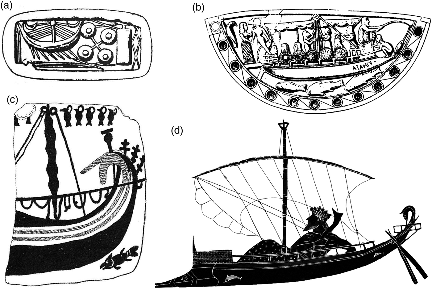
The concept of redirecting a force by using a rope passed over a frame must have been obvious throughout the Eastern Mediterranean from early times. Indeed, in this area depictions of ancient vessels dating from the Bronze Age onwards (Fig. 16) show that sails were manoeuvred by pulling and releasing brails passing over the yard and were raised by pulling on halyards that passed through holes or other devices, if not around true pulleys.Footnote 85 The sail vessels pictured on Greek vases from the seventh and sixth centuries seem to rely on similar technology. The ship represented on an ivory plaque from Sparta (Fig. 16b), found in a deposit dated by Laconian II pottery (620–570) (Dawkins Reference Dawkins1929, 214–15 pls. 109, 110), features a masthead provided with one circular device that could be interpreted as a pulley.Footnote 86 On a seventh-century votive plaque from Corinth (Fig. 16c) (Casson Reference Casson1971, fig. 98), two such devices appear on the masthead of a merchantman, plausibly representing metal ears for guiding the rigging that raised the yard and sail (halyards). No matter what the device on the masthead might be, the concept was the same. There can thus be no doubt that in the seventh century Greek shipwrights had mastered such technology. Furthermore, the Corinthians' primacy in this realm is well known from Thucydides, who recounts both that they invented the trireme and were the first to modernize shipbuilding techniques, and that the Corinthian shipwright Ameinocles was commissioned to build four ships for the Samians at the end of the eighth century.Footnote 87
(a) Minoan seal (c. 2000–1600 bc) showing a circular device on top of a ship mast. Drawing by the author, after Casson Reference Casson1971, fig. 48. (b) Ivory plaque found at Sparta (620–570 bc) showing what seems to be a pulley on top of the masthead. Drawing by the author, after Dawkins Reference Dawkins1929, 215 pl. 110. (c) Stern of a merchantman with two ‘ears’ on the masthead, depicted on a 7th-century votive plaque found at Corinth. Drawing by the author, after Casson Reference Casson1971, fig. 98. (d) Dionysus's boat from the cup by Exekias (540–530 bc), showing ‘ears’ on the masthead. Drawing by the author.

In the mast-and-yard system of an Archaic Greek sailboat, all the main components of a crane were already present, with the exception of hoistsFootnote 88 and winches, namely: a vertical structure with stabilising ropes (forestay and backstay); an arm with lateral mobility (yard with braces); and ropes pulled down vertically or at an angle (halyards and brails) to raise loads. Shipbuilding technology might well have triggered the development of the first lifting machines, which might then have been applied to construction. Indeed, on sailing vessels, the presence of ropes and masts would have encouraged experimentations, especially when loading cargo.Footnote 89 It seems perfectly plausible, therefore, that the Corinthians of the seventh century might have lifted the first ashlar blocks of Greek architecture by using ropes and a framework that might be regarded as a primitive lifting machine.
LIFTING AND THE FINAL SETTING OF THE BLOCKS
Further aspects of the evidence from Isthmia
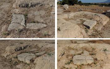
Two aspects of the evidence from Isthmia that have been overlooked in previous scholarship suggest that the grooves on the temple's ashlar blocks would not only have served for lifting. First, all of the broad blocks Broneer assigned to the single-step stylobateFootnote 90 of the early temple (Fig. 17) consistently exhibit parallel grooves, although these blocks were laid in a shallow trench in the ground and therefore would not have required lifting. Second, the only non-grooved stones of this temple belong to the single-course foundation below the stylobate (Fig. 18).Footnote 91 Interestingly, these foundation stones are also the only ones that were not set against their neighbours with tight joints, as their shape is not perfectly regular and the gaps between them were filled with earth. Only three of these stones are preserved in situ, therefore they do not provide information as reliable as that of the other blocks.Footnote 92 This is no reason, however, to neglect them entirely.
Group 1 blocks from Isthmia. (a) Blocks Ar 1 and Ar 2. Drawing by the author, after Broneer Reference Broneer1971, 17 figs 1–2. (b) The group 1 blocks preserved near the north-west corner of the temple area. Photo by the author.

Foundation stones of the early Temple of Poseidon at Isthmia, found in situ at the eastern end of the north stylobate trench. Photos by the author.

To account for the grooves on the stylobate blocks, one could assume that they might have been used to secure a sling attached to a hand barrow, which would have been a practical way to move these stones horizontally and lay them down. This hypothesis does not exclude lifting machines, which would have been used to lift and place the blocks of the masonry's higher courses. Yet we might wonder why the same method used with stylobate blocks would not be adopted with the foundation stones, some of which are as sizable as the standard blocks of the superstructure.Footnote 93
The reason becomes apparent if we consider the necessary step that followed lifting in the construction process, which was manoeuvring each block into position tightly up against the stones already in place. This was a necessary operation for which these blocks apparently offer no clear evidence. In later periods, this delicate step required special cuttings in the stones, so we would expect the parallel grooves to have served this purpose in addition to lifting. Indeed, at Isthmia, all of the blocks that had to be brought tightly up against adjoining stones have grooves, regardless of whether they needed lifting. Conversely, foundation stones do not have grooves. In addition to the fact that they did not require lifting, this is because their loose joints did not imply close contact. After all, as the next section will show, the occurrence of straight grooves on blocks dating from Pharaonic Egypt to Archaic Greece seems to have been closely related to setting blocks next to their neighbours by ropes, although it was apparently confined to particular kinds of blocks, or blocks in special positions.
Straight rope grooves and setting methods
The earliest parallels that come to mind are from Egypt. While no Egyptian blocks are known to have parallel grooves in the same arrangement as those from the two early temples of the Corinthia, the Egyptians did cut rope grooves on particular kinds of blocks (Fig. 14a). These blocks were set in tight contact with adjoining ones, and the grooves allowed for laying them down with ropes, as well as for the ropes' removal, which would have been impossible otherwise. Examples include sarcophagus lids, closing stones of crypts, portcullises, keystones, pavement slabs and repair stones (Arnold Reference Arnold1991, 118, 219–20, 223, figs 4.13–14, 4.66, 5.9).
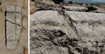
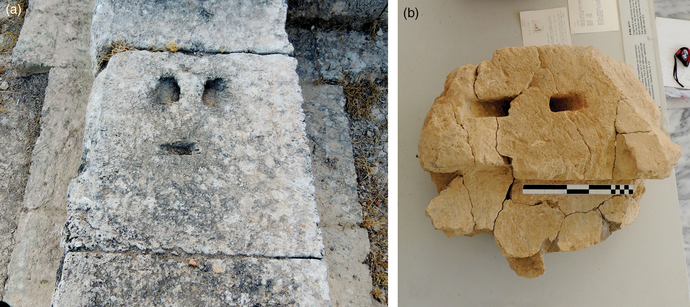
The blocks that most closely resemble those from the early temples of Corinth and Isthmia are from Greece. They were found at Phlius, in ancient Argolid, built into walls and graves during the Roman period, but they originally belonged to a building of which nothing is known.Footnote 94 Only four blocks are preserved today at the museum in Nemea (Fig. 19), all with inscriptions on the exposed side, which suggests that they might be from a sacred building. The characters in the earliest of these inscriptions also suggest a terminus ante quem for the building within the first half of the sixth century. Like the early Corinthian blocks, those from Phlius have parallel grooves on the bottom and on one side, and they also resemble early Corinthian blocks in material and dimensions. The only remarkable difference is that, in addition to the parallel grooves, the blocks from Phlius feature a semi-cylindrical cutting in the middle of the grooved side. Because their paucity and lack of original context makes the blocks difficult to interpret, we cannot determine whether the semi-circular cutting was an original feature or resulted from a later use. All we can gather is that the experimental building method at Isthmia and Corinth had followers in the subsequent century within a radius of about 30 km from the area of its early development.
One of the four Archaic blocks with grooves found at Phlius, presently housed at the museum in Nemea. Photos by the author.

Other significant parallels from the Greek world are found at Perachora, in the Corinthia, and at Selinus and Akragas, in Sicily. At Perachora, the blocks of the north interior stylobate of the Temple of Hera Akraia (last quarter of the sixth century) feature a groove extending from side to side across the bottom (Fig. 20), near the end that would have abutted the block already in place during setting manoeuvres. Indeed, this groove would have allowed the corresponding end of the block to be lifted and lowered while the block was being set against its neighbour (Menadier Reference Menadier1995, 16–17 fig. 9).
Blocks of the north interior stylobate of the late 6th-century Temple of Hera Akraia at Perachora, each with a groove extending from side to side across the bottom. Photo by the author.

At Selinus, some geison blocks from Temple C (mid to late sixth century) have a couple of longitudinal grooves on the underside that turn up on both ends. Such cuttings occur on only a few blocks, while the rest of the cornice blocks have none. This might suggest that the grooves were used for laying blocks down in particular positions, perhaps by manoeuvring a loop of rope with levers.Footnote 95 According to Koldewey and Puchstein (Reference Koldewey and Puchstein1899, 225), the geison blocks from Temple C that are provided with grooves were the last ones laid on their course,Footnote 96 as later proposed by Broneer for Ar 40, the block from Isthmia featuring grooves on both ends.Footnote 97
At Akragas, in the Olympieion (begun in the early fifth century), sets of two grooves running parallel to the architrave are found along the resting surface of the engaged columns' lower capital-blocks, as well as along their vertical joints (Koldewey and Puchstein Reference Koldewey and Puchstein1899, figs 140, 143; Durm Reference Durm1910, fig. 72; Stuart and Revett Reference Stuart and Revett1830, pl. VIII fig. 13); they are interpreted by Koldewey and Puchstein (Reference Koldewey and Puchstein1899, 162) as rope-grooves. The only ends of them remaining visible inside the neck-flutes were easily sealed with properly fashioned stone patches. Each of these blocks comprises a half echinus and, below it, the corresponding top end of the fluted semi-column. Apparently, only the right-hand block of each echinus has grooves on the vertical joint passing through the capital's centre. These would have been needed for removing the ropes if the left side was already in place.Footnote 98
In brief, in Greece and in Egypt straight rope grooves seem to have been used in the final setting of stone blocks. At any rate, the generalised use of grooves on all of a building's blocks, as in the early temples at Corinth and Isthmia, seems to be an isolated case, unless the grooved blocks from the Temple of Hera Akraia at Perachora are remnants of a seventh-century predecessor, all of whose blocks might have had the same kind of groove.Footnote 99
Reconstructing the setting method
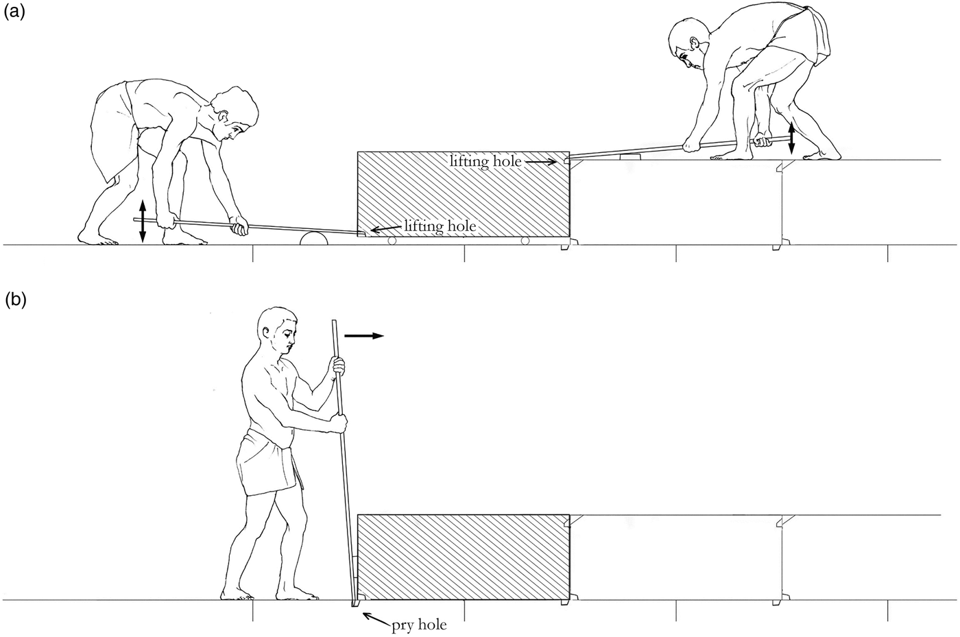
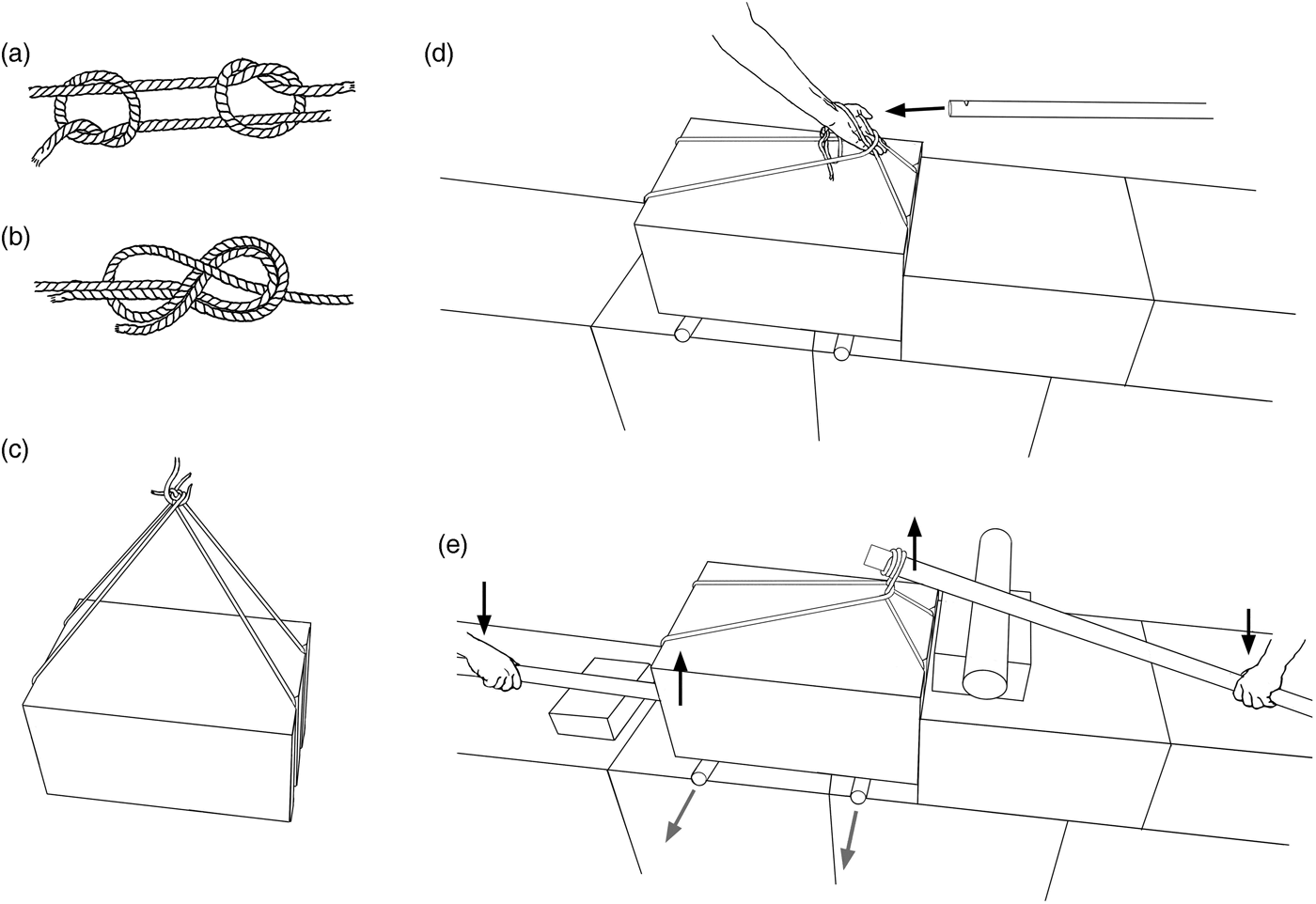
Once a connection is established between the grooves and the final setting of the blocks, the question now becomes how this operation was performed and how it related to lifting. According to Hemans (Reference Hemans, Gebhard and Gregory2015, 46), lifting and setting a block into position were performed in a single step, assuming that a lifting machine could deliver the block precisely to the final position so that no further adjustment would be needed. This is highly improbable, as testified by the complex manoeuvres this operation would require in later periods, when the blocks were lifted to their course by a crane placed against the wall's midpoint, laid down on rollers, and moved horizontally to their final place, where they were lowered with crowbars.
Hero (Mechanica 3.2) and Vitruvius (10.2.8–10) describe a single-arm crane offering ample mobility (Fig. 21). However, in spite of the wide horizontal reach of this device, we know from Hero's account that, even with this machine, a block was likely laid down near its final position and then pushed the last few centimetres to its home against its neighbour in the usual way, on rollers. Moreover, while he praises the ingenuity of this machine, Vitruvius adds that it was only for experts. These accounts reflect the knowledge of the Hellenistic period, when considerable experience had been gained in lifting and other technological realms. That a machine in the seventh century could outperform a Hellenistic one is hard to believe, given that lifting technology was presumably in its early stages.
Single-arm lifting machine described by Vitruvius (10.2.8–10), with a compound pulley system (polyspastos) but no winch. Galiani Reference Galiani1758, pl. XXV.

Therefore, manoeuvring was most likely performed after and independent of lifting. In the Classical and Hellenistic periods, this operation usually involved the following steps. First, once a block was brought against its neighbour, the rollers were removed. This was done with crowbars, which lifted the block from two points, the bottom of the free end and the top of the contact end, where special holes had been cut in the middle for accommodating the ends of the crowbars (Fig. 22a). Then, as the block was lowered, contact between the adjoining faces was tested and adjustments made by levelling out potential imperfections. Once this was done and the block was laid down on its bedding, the free end was pushed in order to tighten the joint. This last step required that a pry hole (or two) in the course below it be present to provide purchase for the crowbar (Fig. 22b).Footnote 100
Setting by manoeuvring with levers accommodated by specific cuttings. (a) Once a block has been brought on rollers against its neighbour, the block is lifted with levers at two points and the rollers removed. The block is then lowered. (b) The free end of the block is pushed to tighten the joint. Drawings by the author.

The blocks from the early temples of Isthmia and Corinth may have been set into position in one of two ways: by using levers; or by using a combination of ropes and levers. Levers would have been feasible on a practical level, as in most cases the anathyrosis is deep enough in the centre to allow the tip of a lever to be extracted after a block was lowered onto its bedding. Moreover, some of the wall blocks from Isthmia present a rough cutting, 0.10–0.15 m wide and about 0.03–0.04 m deep, that is particularly interesting in this connection, a fact that has thus far been overlooked. This cutting was intentionally carved (apparently with an adze) in the middle of the side face's bottom edge. As we have seen, this is where a lever hole is likely to be found on later Greek blocks, so it seems reasonable to hypothesise that the cutting at issue was carved specifically for use with a lever.
The blocks from Isthmia thus offer the earliest Greek evidence for lever holes and confirm that levers were employed in setting the first stone blocks of Greek monumental architecture. In particular, on some blocks from the ends of Broneer's reconstructed wall, the cutting is found on the exposed non-grooved end (Fig. 23), which would have been the free end while the block was being manoeuvred into place.Footnote 101 This would seem to suggest that the lever was used to lift and lower this end in the very same way as later practice. However, while examination of the ends of Broneer's reassembled blocks is often difficult (in some blocks this part is not even preserved), it does show that there are blocks on which the cutting is absent. Moreover, on others the cutting is found on the opposite side, the one with grooves. For this fact I have no better explanation than that the builders, while accustomed to using levers for moving stones (presumably from quarrying), might have discovered the best method during the process of experimenting with different setting techniques.
Rough cuttings at the lower edge of the free, non-grooved end of the blocks at Isthmia. (a) Block IA 852, at the eastern end of the taller portion of Broneer's reconstructed wall. (b) Blocks IA 851 (bottom) and IA 3576 (top), at the opposite end of the same portion of the wall. Photos by the author.

Besides using a lever to lift and lower the free end of a block, later practice required a means for pushing the free end and a means for lifting the side of the block near the neighbouring stone. Would our blocks have allowed these two additional operations? As to pushing the free end after lowering the block on its bedding, I believe that, even without a pry hole, a wooden lever inserted into the gap between the bedding and the slightly concave underside of the block – or into the special cutting described above, if present – would have had sufficient grip on the rough limestone surface to move the block, considering its relatively modest weight and the fact that, generally, crowbars are more effective when they are inclined against rather than perpendicular to the direction of action (in order not to slip out). The grooves would have provided the only means of lifting and lowering the opposite side of the block. Because a lever was used on the free end, it seems logical that the same means would also be adopted on the contact end for pulling a loop of rope, so that two men, one on each side of the block, would suffice for the job (Figs 24e and 25a).
(a) Fisherman's knot (consisting of two overhand knots). (b) Flemish bend (consisting of a double figure eight bend). (c) Sling for suspending a block, consisting of a loop of rope accommodated in the grooves. (d) Attaching the sling to a lever. (e) Using levers for moving the block vertically (and removing the rollers). Drawings by the author.

Setting technique (1: lifting and lowering; 2: pushing) and the conjectural development of ways of lifting the contact end of a block with levers. (a) Lever attached to a rope accommodated by grooves in the blocks of the early temples at Isthmia and Corinth. (b) Lever attached to a loop of rope accommodated by a V-shaped hole. (c) Lever's tip accommodated by a specific cutting below the upper edge of the block's contact face. Drawings by the author.

There is no evidence as to how the rope was tied around each individual block to form a sling for lifting or, later during setting, how exactly the rope was attached to the lever at the contact end. From a practical standpoint, though, the setting method proposed above could only work if, after lifting, the sling could be easily and quickly attached to the lever, and then just as easily untied to remove the rope once the block was set. Among the most reliable knots used today for joining two ends of a line under load are the fisherman's knot and the Flemish bend (Fig. 24a, b). These are double versions of the overhand knot and the figure eight bend, respectively, which are both attested from Egyptian times onwards.Footnote 102 There can be little doubt that the Greeks, who were skilled sailors, mastered these knots and their variations from early times.
With a sling made from a loop of rope (Fig. 24c) it would have been easy to equalize the rope lengths above a block to ensure that its resting face stayed horizontal during lifting. If such a sling was used, after the block had been laid down and brought against its neighbour, the same sling could be easily attached to a lever (in a position convenient for lifting the block's end) by passing one of the loop's ends through the other and then around the lever's tip a number of times (twisting the loop at each successive round) (Fig. 24d, e).Footnote 103 Once the block had been set, untying either of the knots mentioned above would have only taken a matter of seconds, for they are relatively easy to loosen once the tension is over.
Developments in setting technique
The use of linear grooves continued throughout the Archaic period, but sporadically and on blocks of special categories.Footnote 104 In subsequent Greek Archaic architecture, the characteristic V-shaped holes (Fig. 26) that I have discussed in connection with lifting appeared on the top face of blocks (references in Coulton Reference Coulton1974, 2 n. 8). While the presence of one or two such holes near the centre of the top face points to lifting as the sole purpose, two V-shaped holes, one located near each end,Footnote 105 would have permitted both lifting and the final setting, as I have argued was the case for the parallel grooves. Indeed, after lifting, a loop of rope attached to the cutting near the neighbouring stone would have allowed workmen to lift and lower this side with a lever (Fig. 25b) in much the same way, I believe, as with the grooves of the Early Archaic Corinthian blocks (Coulton Reference Coulton1974, 2 fig. 2).
V-shaped holes on Archaic blocks. (a) A wall block from a lower course of the Temple of Hera Akraia at Perachora, with an off-centre V-shaped cutting and a pry hole. (b) Fragment A 163 from the early Temple of Zeus at Nemea. Photos by the author.

However, in most cases there seems to have been only one V-shaped hole near one end, for which the only plausible purpose would have been manoeuvring a block into place. In fact, if such a cutting were used for suspending a block, this would hang almost vertically (Coulton Reference Coulton1974, 2). The earliest examples of such off-centre cuttings in Archaic Corinthian architecture appear on foundation blocks of the Corinthian Treasury at Delphi, a building dedicated by Kypselos (reign 657–627) and consequently dated immediately after the early temples of Corinth and Isthmia (references in Pfaff Reference Pfaff, Williams and Bookidis2003, 105 n. 84). Later examples appear, in the Corinthia, on some foundation and wall blocks of the Temple of Hera Akraia at Perachora (Fig. 26a) and on some reused blocks in the Sanctuary of Demeter and Kore at Corinth, as well as on a few other isolated Corinthian blocks (Pfaff Reference Pfaff, Williams and Bookidis2003, 107). Similar cuttings appear also at Olympia, on the wall ashlars of the Temple of Hera (Durm Reference Durm1910, fig. 71), and in ancient Argolid, on the geison blocks of the Archaic temple on the Acropolis at Mycenae (Klein Reference Klein1997, 283–5, figs 10, 15) and on blocks from the early Temple of Zeus at Nemea (Fig. 26b).Footnote 106 In particular, the temple at Nemea shows striking similarities with those from the early temples at Isthmia and Corinth, suggesting that this building should be regarded as their most direct descendant.
Unlike the blocks from Corinth and Isthmia, those with off-centre V-shaped holes from later Archaic contexts also, in some cases, have pry holes (Fig. 26a).Footnote 107 Providing much better purchase for levers than shear friction, pry holes represent the Greeks' best solution for pushing stones.Footnote 108 V-shaped holes placed near the contact end, no matter how soon they were used with tongs, seem reminiscent of their forerunners, rather than being on the verge of the next technological advance. As we have seen, in later periods, lifting the contact face of a block would involve a special cutting near its top edge, as well as a corresponding cutting on the neighbouring stone (Figs 22a and 25c). These sophisticated cuttings allowed the lever more control and were better suited for marble blocks.Footnote 109
CONCLUSIONS
The study of the stone blocks from the early temples at Isthmia and Corinth offers enough information to reconstruct the way in which their characteristic grooves were most plausibly used. More generally, the material also reveals important clues for understanding the beginnings of stone construction in Greece. Study of groove depth, maximum block weight and rope strength shows that the original thesis that the grooves were used in lifting is technically plausible. Moreover, this thesis seems more compelling in explaining the grooves' peculiar dispositions than the alternative theory that they were used in quarrying.
As to lifting technique, Coulton's thesis that fully developed cranes with mechanically advantageous devices spread in the Greek world only in the late sixth century is still convincing. However, simpler machines seem to have been used for moving loads vertically by redirecting traction in the Eastern Mediterranean and Near East since the Bronze Age. Familiarity with this basic concept is proven by its usual application to ship technology, as shown by representations of sail boats from the Bronze Age through the Archaic period. In particular, Archaic Corinthian ship depictions confirm that this technology was known in the region. After all, beginning from the Early Geometric period, the Corinthians also seem to have employed a similar technique on dry land for lowering their massive sarcophagi into narrow pits.
It is impossible to say exactly when the hoist and winch were invented. However, while the size of the largest blocks used in construction was reduced in the late sixth century, presumably as a consequence of the relatively limited loading capacity of the first cranes, this capacity was still in the order of several tons. Therefore, it is likely that both the winch and the hoist were already part of the crane by that time.Footnote 110 In particular, the winch might have been adopted in the Corinthia early in the Archaic period. This is suggested by rope marks and holes found in a section of the Diolkos – the paved trackway created across the Isthmus under Periander (625–585) – presumably resulting from hauling heavy cargo with capstans (Raepsaet Reference Raepsaet1993, 255), a kind of winch. If true, then it is reasonable to assume that experiments with wooden frameworks (previously used to redirect pull) combined with mechanically advantageous traction mechanisms had been performed in construction during the sixth century, and that an increase in loading capacity had accompanied this technological progress. This development seems consistent with the sequence of maximum loads early machines could lift, from the geison blocks of the mid-seventh-century temple at Isthmia (up to c. 360 kg) to the drums lifted at several sites (Olympia, Aegina, Delphi) since the beginning of the following century (about 1 ton), and eventually to the capital of the mid-sixth-century Temple of Apollo at Corinth (5 tons).
Last but not least, the setting method with which Corinthian builders had experimented by the mid-seventh century seems to be at the very beginning of the technique later employed throughout the Classical and Hellenistic periods. Rudimentary though it may appear, this early method, which used a combination of ropes and levers, must nonetheless have been effective with blocks of modest size, at least to some degree. The development of this technique would not have been linear, and the cuttings on Archaic Greek blocks from different areas (or, in some cases, even from the same site) suggest that builders were experimenting with a variety of solutions at the same time. Yet some stages of setting technique's development can be traced through the evidence, in particular as concerns lifting the contact end: from the parallel grooves at Corinth and Isthmia (Fig. 25a) to the single groove on blocks of the Archaic Temple of Hera Akraia at Perachora and off-centre V-shaped cuttings (Fig. 25b), to finally arrive at the distinctive lever hole used from the Classical period onwards (Fig. 25c).
ACKNOWLEDGEMENTS
I am particularly indebted to Jim Coulton, who helped me develop and strengthen my arguments, and to Manolis Korres, from whom I learned much about the manoeuvring of stone blocks. I am also grateful to Elizabeth Gebhard, Chris Hayward, Nils Hellner, Dieter Mertens, Clemente Marconi, Giorgio Ortolani, Robin Rhodes, Ingrid Rowland, John Stamper and Paolo Vitti, who have all generously shared their expertise and advice. Any errors that remain are my own. Finally, I thank all those who supported my fieldwork, and in particular: K. Kissas and S. Koursoumis (37th Ephorate for Prehistoric and Classical Antiquities); Guy Sanders, Nancy Bookidis, Ioulia Tsonou-Herbst, James A. Herbst and Nikol Anastasatou (American School of Classical Studies at Athens, Excavations in Ancient Corinth); and E. Gebhard and J. Perras (University of Chicago Excavations at Isthmia).