I. INTRODUCTION
Solidification is one of the major manufacturing processes of most metallic products. This process plays important roles not only in shaping alloys into desired products but also in controlling the macro- and microstructures of the alloys that have significant effects on the final properties of products. With the development of new techniques, there has been an extensive growth of experimental research and accompanying theory on the solidification of alloys. For instance, applying a high magnetic field (HMF) to the solidification process to regulate and control the alloy structures has recently become a research focus. With the HMF, magnetization force, Lorentz force, and even thermoelectric magnetic force can be induced to affect the solidification structures. The magnetization force brings about regular alignments and distribution modification, Reference Mikelson and Karklin1,Reference Savitsky, Torchinova and Turanov2 the Lorentz force suppresses gravity segregation, Reference Wang, Wang, Wang, Li, Nakajima and He3,Reference Li, Zhao, Zuo, Zhu and Cui4 and the thermoelectric magnetic force leads to a morphological change of crystals. Reference Li, Fautrelle, Gagnoud, Cao, Zhang, Ren, Lu and Esling5–Reference Du, Guan, Gagnoud, Fautrelle, Ren, Lu, Wang, Dai, Wang and Li7 Such effects of the HMF have been widely verified during the solidification process of various metallic alloys like Cd–Zn, Reference Mikelson and Karklin1 Bi–Mn, Reference Savitsky, Torchinova and Turanov2 Al–Ni, Reference Wang, Wang, Wang, Li, Nakajima and He3 Al–Mn, Reference Li, Zhao, Zuo, Zhu and Cui4 Al–Cu, Reference Li, Fautrelle, Gagnoud, Cao, Zhang, Ren, Lu and Esling5,Reference Li, Gagnoud, Ren, Fautrelle and Debray6 Zn–Cu, Reference Du, Guan, Gagnoud, Fautrelle, Ren, Lu, Wang, Dai, Wang and Li7 Al–Fe, Reference Li, Zhang, Esling, Jiang, Zhao, Zuo and Cui8 Al–Zr, Reference Li, Zhang, Esling, Qin, Zhao, Zuo and Cui9 Mn–Sb, Reference Liu, Wang, Zhang, Gao, Li and He10–Reference Liu, Wang, Gao, Zhang, Wang and He12 Pb–Sn, Reference Li, Xu, Tong, Zhang, Ban, He, Zhao, Zuo, Zhu and Cui13 Al–Si–Fe, Reference Asai14,Reference Du, Lu, Gagnoud, Fautrelle, Ren, Lu, Moreau and Li15 and Al–Ti–B. Reference Li, Zhu, Zhang, Zuo, Ban, He, Liu and Cui16 For instance, as early as the last century, Mikelson et al. reported that the macrostructures of Al–Cu and Cd–Zn alloys aligned in the direction of the magnetic field. Reference Mikelson and Karklin1 More recently, Wang et al. showed that the primary Al3Ni phase in Al–Ni alloy aligned regularly in the direction perpendicular to the HMF. Reference Wang, Wang, Wang, Li, Nakajima and He3 Meanwhile, they also found that the HMF tended to impede the descendant of the Al3Ni phase in the melt. Du et al. disclosed that the HMF caused deformation and columnar-to-equiaxed transition (CET) of the ε-CuZn5 dendrites during the directional solidification of Zn–Cu peritectic alloys. Reference Du, Guan, Gagnoud, Fautrelle, Ren, Lu, Wang, Dai, Wang and Li7
However, despite these extensive investigations, the research alloys are mainly concentrated in binary ones—only few complex alloys were involved. Compared to the binary alloys, more phases are created to form more complicated structures in the complex alloys. Under the effects of a HMF, the created phases with different magnetocrystalline anisotropies may show different growth characters, and meanwhile, they may also interact with each other during the solidification process. Therefore, it is of potential interest to investigate the effects of a HMF on the solidification structures of complex alloys in which different phases coexist. In our previous studies on binary Al–Fe Reference Li, Zhang, Esling, Jiang, Zhao, Zuo and Cui8 and Al–Zr alloys, Reference Li, Zhang, Esling, Qin, Zhao, Zuo and Cui9 it has been found that the primary Al3Fe (monoclinic structure) and Al3Zr (tetragonal structure) phases possess different crystallographic growth morphologies and show different alignment and segregation characters under the HMFs. However, the case in which Al3Fe and Al3Zr phases coexist in a complex alloy under a HMF has not been reported. Based on such a context, Al–Fe–Zr ternary alloy was solidified under different HMFs. The effects of the HMFs on the solidification structures in this complex alloy, including the growth forms, distribution, and alignments of the primary Al3Fe and Al3Zr crystals, were carefully studied. The supposed three-dimensional alignments Reference Li, Zhang, Esling, Jiang, Zhao, Zuo and Cui17 and the calculated three-dimensional growth habit of the tabular Al3Zr crystals in our previous work Reference Li, Zhang, Esling, Qin, Zhao, Zuo and Cui9 were also verified by means of deep etching.
II. EXPERIMENTAL
The ternary Al–Fe–Zr alloy used in the present work was prepared by melting pure aluminum (99.95 wt%), pure iron (99.99 wt%), and Al–10 wt% Zr intermediate alloy in an induction furnace. After the melt had been magnetically stirred and held at 1200 °C for 30 min, a further mechanical stirring was imposed to homogenize the composition of the alloy in the whole melt, and then the melt was poured into a high-purity water-cooled copper crucible to solidify quickly into a billet. The final chemical composition of the prepared alloy was verified to be Al–2.35Fe–0.5Zr (at.%) by an inductively coupled plasma atomic emission spectrometry method. Some round rods were machined from the cast billets. The experimental setup has been introduced elsewhere in detail. Reference Li, Zhang, Esling, Qin, Zhao, Zuo and Cui9 In the present work, each rod was put into a tube of high-purity corundum crucible (10 mm in inner diameter and 60 mm in height) and then placed in the central region where the magnetic field is relatively uniform within ±20 mm. After the magnetic flux density B reached the set value (0, 3, 5, 8.8, and 12 T), the rod was heated up to 960 °C under an vacuum atmosphere by an electric heater at a rate of 5 °C/min and held at this temperature for 40 min, and then furnace-cooled to room temperature (about 10 °C/min). Finally, a solidified ingot (10 mm in diameter and 12 mm in length) was obtained.
Specimens were cut longitudinally (parallel to B) or transversely (perpendicular to B) from the ingots and then mechanically polished for further examination. The phase composition was determined with X-ray diffraction (D/max-2500 PC, Rigaku Corporation, Tokyo, Japan). The macro/microstructures of the specimens were observed on a Leica DMR optical microscope, following a standard mechanical polishing. After a further electrolytic polishing, EBSD auto scanning was also performed on the Al3Zr sedimentary deposit layer with a step size of 2 μm, using a Zeiss ULTRA PLUS FE-SEM (Carl Zeiss, Oberkochen, Germany) equipped with Oxford-HKL Channel 5 system and energy dispersive spectrometer (EDS). Finally, the specimens were deep-etched in sodium hydroxide solution (72 g NaOH: 300 mL H2O) for 5 min to observe the three-dimensional morphologies of the Al3Zr phases.
III. RESULTS
A. Morphology
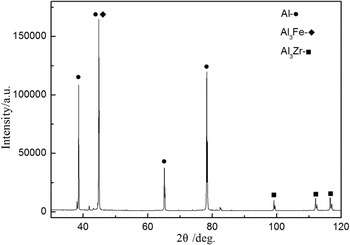
Figure 1 shows the X-ray pattern of the Al–Fe–Zr specimen solidified without the HMF. As can be found, the alloy consists of α-Al, Al3Fe, and Al3Zr phases (here it should be mentioned that the application of a HMF has no effect on the phase compositions of the alloy).
X-ray pattern of the Al–Fe–Zr specimen solidified without the HMF.

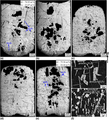
Figures 2(a)–2(e) show the longitudinal macrostructures of the Al–Fe–Zr specimens under various HMFs. It can be observed that some gray long bars or needles are distributed in the brighter matrix, and a gray sedimentary deposit layer is formed at the bottom of each specimen (here it should noted that the convex and concave bottom shapes of the specimens arise from the utilization of corundum crucibles with different bases). EDS analysis indicates that the long bars and the needles are respective primary Al3Fe and Al3Zr phases (see the detected composition data inserted in Figs. 2(a) and 2(e), respectively), and the gray phase in the deposit layers is short-dimensioned Al3Zr. To morphologically distinguish these phases, Fig. 2(f) shows the BSE images corresponding to the positions close to and in the deposit layer of the 12 T specimen, respectively. In the upper image, the coarse gray primary Al3Fe crystals embedded in the black Al matrix show irregular morphologies with bifurcation and gaps, whereas the brighter primary Al3Zr crystals reveal needle-like form. Besides, some gray fine fiber-like eutectic Al3Fe crystals also appear. In the lower image, the brighter short-dimensioned primary Al3Zr crystal displays plate- or bar-like morphologies.
Longitudinal macrostructures of the specimens with B of (a) 0, (b) 3, (c) 5, (d) 8.8, and (e) 12 T, respectively; BSE images (f) corresponding to the positions close to and in the deposit layer of the 12 T specimen, respectively. The arrows denote the primary Al3Fe and Al3Zr phases. The insets in (a) and (e) show the detected composition data of the primary Al3Fe and Al3Zr, respectively.

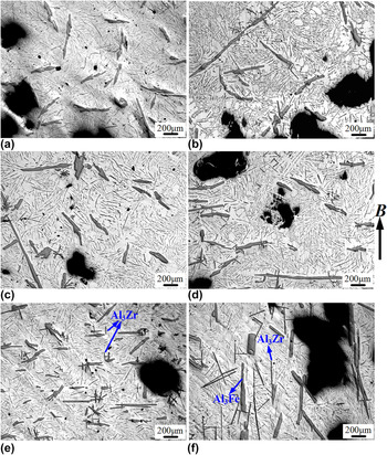
Obviously, the distributions and alignments of the primary Al3Fe and Al3Zr crystals are remarkably affected by the HMF. With the increase of the HMF, as denoted by the arrows in Fig. 2, the bar-like primary Al3Fe crystals tend to be distributed homogeneously throughout the whole specimen and align horizontally (i.e., with the longer axis perpendicular to B), while the needle-like primary Al3Zr crystals tend to be levitated and align vertically (i.e., with the longer axis parallel to B). Such tendencies can be more clearly observed in the microstructures in Figs. 3(a)–3(e), corresponding to the upper parts of Figs. 2(a)–2(e), respectively. Especially in the upper part of the 12 T specimen [Fig. 3(e)], it can also be observed that some fine needle-like Al3Zr crystals appear and align vertically (as denoted by the arrows). This further proves that a strong HMF has a “levitation” effect on the primary Al3Zr phase. However, it should also be noted that, despite the horizontal alignment of the primary Al3Fe crystals in the upper part of the 12 T specimen, they align vertically in the lower part, as shown in Fig. 3(f). This differs significantly from the horizontal alignment throughout the whole specimen in binary Al–Fe alloy. Reference Li, Zhang, Esling, Jiang, Zhao, Zuo and Cui8 Moreover, the needle-like Al3Zr crystals surrounding these Al3Fe crystals are much coarser than those fine ones in the upper part. However, they still remain vertical alignment.
Microstructures corresponding to the upper parts of Figs. 2(a)–2(e) with different HMFs: (a) 0, (b) 3, (c) 5, (d) 8.8, and (e) 12 T, respectively. Microstructure (f) corresponding to the lower part of the 12 T specimen.

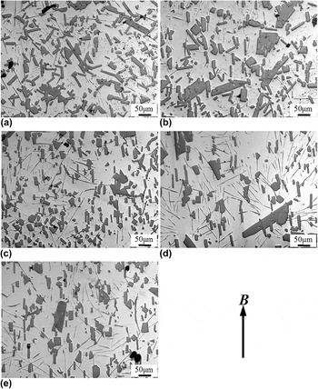
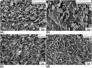
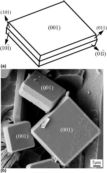
In the deposit layers, as shown in Figs. 4(a)–4(e), the short-dimensioned primary Al3Zr crystals also tend to align regularly as the HMF increases—with their longer axis parallel to B. Moreover, few primary Al3Fe crystals are also observed, which has no remarkable influence on the alignment of the Al3Zr crystals. To understand the effects of the HMFs on the three-dimensional alignment of the Al3Zr crystals, Figs. 5(a) and 5(b) show the SEM images of the deep-etched deposit layers in the longitudinal sections of the specimens without and with the 12 T HMF, together with Figs. 5(c) and 5(d) corresponding to the cross sections, respectively. Obviously, the primary Al3Zr crystals in both specimens reveal tabular form in three dimensions. However, without the HMF, the primary Al3Zr crystals in the longitudinal and cross sections show similarly irregular alignment [Figs. 5(a) and 5(c)]. When the 12 T HMF is applied, strong macrostructural anisotropy appears—some of them reveal plate-like form in the longitudinal section [Fig. 5(b)] while almost all of them show bar-like form in the cross section [Fig. 5(d)]. This indicates that the primary Al3Zr crystals align with their large surfaces parallel to the HMF. With a more careful observation in the longitudinal section, it can also be found that the primary Al3Zr crystals have their two opposite corners on the large surfaces toward ± B [see crystals A and B in Fig. 5(b)]. As a matter of fact, such morphology proves the supposed three-dimensional alignment of the tabular Al3Zr crystals under a HMF in our previous work. Reference Li, Zhang, Esling, Qin, Zhao, Zuo and Cui9 Moreover, it has also been calculated in our previous work that the relatively large tabular Al3Zr crystals are bound by {001} (corresponding to the large surfaces) and {101} faceted planes, as schematically shown in Fig. 6(a). Reference Li, Zhang, Esling, Jiang, Zhao, Zuo and Cui17 In this work, such a habit is also verified by the magnified SEM image, as shown in Fig. 6(b).
Microstructures corresponding to the denoted positions of (a) 1, (b) 2, (c) 3, (d) 4, and (e) 5 in the deposit layers in Figs. 2(a)–2(e), respectively.

SEM images of the deep-etched deposit layers in the longitudinal sections with (a) 0 T and (b) 12 T and in the cross sections with (c) 0 T and (d) 12 T HMFs, respectively.

Calculated three-dimensional growth habit (a) and magnified SEM image (b) of the tabular Al3Zr crystals in the deposit layers.

B. Crystallographic orientation
The strong macrostructural anisotropy of the primary Al3Fe and Al3Zr crystals implies that preferential crystallographic orientations should exist under the actions of the HMFs. By individual orientation measurement of the manually chosen points, it has been determined in our previous work that for the primary Al3Fe crystals [100] is the preferred crystallographic axis, Reference Li, Zhang, Esling, Jiang, Zhao, Zuo and Cui8 whereas for the needle-like primary Al3Zr crystals, their crystallographic directions vary between 〈100〉 and 〈110〉 in B. Reference Li, Zhang, Esling, Qin, Zhao, Zuo and Cui9
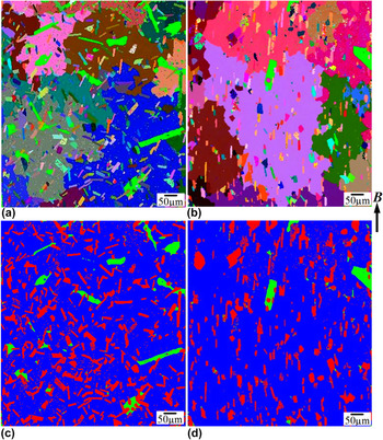
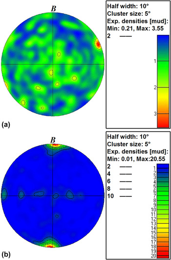
For the short-dimensioned tabular Al3Zr crystals in the deposit layers, EBSD auto scanning was performed in this work, which is different from the previous individual orientation measurement method. Reference Li, Zhang, Esling, Qin, Zhao, Zuo and Cui9 Based on the acquired crystallographic orientation data, the all-Euler orientation micrographs in the central deposit layers of the specimens without and with the 12 T HMF are shown in Figs. 7(a) and 7(b), along with the corresponding phase maps in Figs. 7(c) and 7(d) (Al3Zr—red; α-Al—blue), respectively. The different colors in the orientation micrographs indicate that the tabular Al3Zr crystals and the α-Al grains are differently oriented. However, the HMF induced regular alignment of the tabular Al3Zr crystals in the phase maps suggests that there should exist a specific crystallographic direction with respect to B. To prove this, Figs. 8(a) and 8(b) show the contoured 〈110〉 direction pole figures corresponding to the Al3Zr crystals in Figs. 7(a) and 7(b), respectively. The images to the right of the pole figures display the multiples of uniform densities (MUD) in different colors. In Fig. 8(a), some relatively strong poles are distributed randomly with respect to B, and the maximum MUD corresponding to the strongest pole close to the outer circle is only 3.55. In Fig. 8(b), a strong pole emerges in the B direction, and the maximum MUD reaches 20.55. All of these suggest that 〈110〉 is the magnetic field preferred axis of the tabular primary Al3Zr crystals in the deposit layers.
All-Euler orientation micrographs in the central deposit layers of the specimens with (a) 0 and 12 T HMF, respectively; Phase maps corresponding to the (c) 0 T and (d) 12 T orientation micrographs in (a) and (b), respectively. The Al3Zr and the α-Al phases in the phase maps are denoted by red and blue colors, respectively.


IV. DISCUSSION
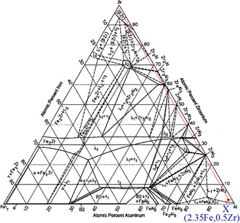
As aforementioned, the solidified ingots consist of α-Al, Al3Fe, and Al3Zr phases whether without and with the HMFs. According to the ternary Al–Fe–Zr phase diagram and the Al–Fe–Zr reaction sequence during the solidification process, Reference Raghavan18 Al3Zr crystals are firstly crystallized from the Al–2.35Fe–0.5Zr melt to form a two-phase region of Al3Zr + L, and Al3Fe then follows this crystallization to form a three-phase region of Al3Zr + Al3Fe + L. With a further drop of the temperature to 650 °C, a ternary eutectic reaction L → Al3Fe + Al3Zr + α-Al occurs. Such a crystallization process accounts for the phase compositions of the solidification structures.
It has been mentioned that the primary Al3Zr crystals reveal two forms (needle-like and tabular) and are mainly located in the lower parts of the specimens, whereas the primary Al3Fe crystals assume bar-like form and are mainly distributed above the primary Al3Zr crystals. Such forms and distributions are intimately correlated with the reheating and cooling processes of the initial rods (obtained from the quickly solidified billet). When the initial rods are reheated to the temperature above the solidus line (650 °C), the α-Al phase begins to melt but some of the original Al3Zr and Al3Fe crystals still remain solid state. As the densities of both the crystalline Al3Zr (4100 kg/m3) and Al3Fe (3896 kg/m3) are much higher than that of the liquid Al (2372 kg/m3 at 950 K Reference Assael, Kakosimos, Banish, Brillo, Egry, Brooks, Quested, Mills, Nagashima, Sato and Wakeham19 ), they tend to descend during the reheating process under the actions of the gravity. However, the unmelted Al3Zr crystals should have a faster descending velocity than that of the unmelted Al3Fe crystals due to their higher density, as a result of which more unmelted Al3Zr crystals are deposited at the bottom of the specimens. With a further increase of the temperature to the two-phase region (Al3Zr + L), the original Al3Fe crystals are completely melted while some Al3Zr crystals still survive (note: according to the computed isothermal section of the ternary Al–Fe–Zr phase diagram at 1000 °C, as shown in Fig. 9 (see the marked composition point X), Reference Raghavan18 the highest reheating temperature 960 °C in this work just corresponds to the two-phase region). During this reheating stage, the unmelted Al3Zr crystals should descend even faster due to the complete melting of the Al3Fe crystals (no impeding effect on the descendant of the Al3Zr crystals) and the reduced viscosity of the Al melt accompanying the raised temperature. When going to the temperature holding stage, the unmelted Al3Zr crystals continue to descend. Finally, the unmelted Al3Zr crystals are deposited at the bottom of the specimens to comprise the segregation layers. When going to the cooling stage, new needle-like primary Al3Zr crystals are crystallized from the melt Reference Li, Zhang, Esling, Qin, Zhao, Zuo and Cui9 and then descend on the segregation layers. With a further drop of the temperature, new bar-like primary Al3Fe crystals are crystallized from the upper part of melt and then descend on the primary Al3Zr crystals [some Al3Fe crystals are also crystallized from the melt trapped between the plate-like primary Al3Zr crystals in the deposit layers (see Fig. 4)]. During this cooling stage, the segregated Al3Zr crystals in the deposit layers also grow and finally form the tabular morphology. Reference Li, Zhang, Esling, Qin, Zhao, Zuo and Cui9
Computed isothermal section of Al–Fe–Zr ternary phase diagram at 1000 °C. Reference Raghavan18

In the binary alloys, it has been widely proved that the application of a HMF can induce magnetic viscosity resistance force (MVRF) to impede the descendant of the primary crystals. Reference Wang, Wang, Wang, Li, Nakajima and He3,Reference Li, Zhao, Zuo, Zhu and Cui4,Reference Li, Zhang, Esling, Jiang, Zhao, Zuo and Cui8 Similarly, this force can also be induced during the reheating and cooling processes of the ternary Al–Fe–Zr alloy, which accounts for the homogeneous distribution of the primary Al3Fe crystals. However, for the primary Al3Zr crystals, it has been shown that the fine needle-like Al3Zr crystals tend to be levitated [Fig. 3(e)] but the large ones are still mainly concentrated in the lower part of the 12 T specimen [Fig. 3(f)]. Such distributions should be related to their crystallization orders from the melt. The coarse needle-like Al3Zr crystals are those crystallized from the melt as the cooling process starts. During this stage, the melt temperature is relatively high, which corresponds to a low melt viscosity and thus a low resistance force. As a consequence, they descend and are finally concentrated in the lower part of the specimen even with the MVRF (in binary Al–Zr alloy, it has been proved that the HMFs have almost no effect on the descendant of the coarse needle-like Al3Zr crystals due to their high density Reference Li, Zhang, Esling, Qin, Zhao, Zuo and Cui9 ). For the fine needle-like Al3Zr crystals, they should be those crystallized from the low-temperature melt (even probably created in the three-phase region). During this stage, the viscosity is increased and the descending time shortened (from initial crystallization to complete solidification of the alloy). These two factors plus the induced MVRF cause the “levitation” of the fine needle-like Al3Zr crystals.
In addition to the effects on the distributions, the HMFs also induce regular alignments of the primary Al3Fe and Al3Zr crystals. As discussed in our previous work, Reference Li, Zhang, Esling, Jiang, Zhao, Zuo and Cui8,Reference Li, Zhang, Esling, Qin, Zhao, Zuo and Cui9 this phenomenon is closely related to the magnetocrystalline anisotropies of the crystals. It is known that magnetic susceptibilities along different axes of a crystal are different. The magnetization energy U i (unit volume) depending on the magnetic susceptibility of the crystal in the B can be expressed as Reference Sugiyama, Tahashi, Sassa and Asai20
 $${U_{\rm{i}}} = -{{{\chi _{\rm{i}}}} \over {2{\mu _0}{{(1 + N{\chi _{\rm{i}}})}^2}}}{B^2}\quad ,$$
where the subscript i denotes the crystallographic direction i,
 $\chi$
is the magnetic susceptibility,
 ${\mu _0}$
the permeability in vacuum, and N the demagnetization factor. From Eq. (1), it can be known that for a paramagnetic crystal (
 $\chi$
> 0), the minimum magnetization energy can be obtained only when the axis of the crystal with the maximum magnetic susceptibility is parallel to B. During the solidification process, the initially crystallized Al3Fe and Al3Zr crystals are randomly orientated. This suggests that the axes of the crystals with the maximum magnetic susceptibilities may be inclined to B at some angle. To adjust them to energetically optimal orientations, magnetic torque T
q will be induced to rotate them with their preferred axes to B, which is usually expressed as20
 $${T_{\rm{q}}} = {{V\Delta \chi {B^2}\sin 2\theta } \over {2{\mu _0}}}\quad ,$$
where V is the volume of the crystal,
 $\Delta \chi$
the magnetic susceptibility difference between the easy and the difficult magnetization axes, and θ the angle between the applied magnetic field direction and the easy magnetization axis. In the present work, 〈100〉 and 〈110〉 are just the preferred axes of the primary Al3Fe and Al3Zr crystals relative to the HMF direction, respectively.
As the anisotropic morphologies of crystals (such as bar-like Al3Fe and tabular- and needle-like Al3Zr) are closely related to their crystal structures, preferred crystallographic orientation will bring about macrostructural anisotropy. For instance, the 〈110〉 just corresponds to the direction connecting the two opposite corners on the large surfaces of the tabular Al3Zr crystals, as denoted by the arrows in crystals A and B in Fig. 5(b). When 〈110〉 is rotated to the HMF direction B, it is natural that the tabular primary Al3Zr crystals have their large surfaces parallel to B so that an anisotropic alignment appears. However, for the primary Al3Fe crystals, it has been shown in this work that they align horizontally in the upper but vertically in the lower parts of the 12 T specimen [Figs. 3(e) and 3(f)]. In the binary Al–Fe alloy, it has been proved that they align horizontally throughout the specimen with a 12 T HMF. Reference Li, Zhang, Esling, Jiang, Zhao, Zuo and Cui8 It is therefore reasonable to suppose that the vertical alignment should be related to the addition of the Zr element. As shown in Fig. 3(f), the primary Al3Fe crystals are surrounded by some coarse needle-like primary Al3Zr crystals. As aforementioned, these needle-like primary Al3Zr crystals are firstly crystallized from the melt and then tend to align vertically. Later, the primary Al3Fe crystals are crystallized but tend to align horizontally. When these primary Al3Fe crystals meet the primary Al3Zr crystals, interactions between them will be unavoidably induced to affect the realignment of the crystals. For instance, as shown in Fig. 3(f), the rotation of the arrowed primary Al3Fe crystal will be hindered by the coarse needle-like primary Al3Zr crystals surrounding it, as a result of which it cannot be aligned horizontally. Similarly, the rotations of the primary Al3Fe crystals in the deposit layers are also impeded by the deposited Al3Zr crystals around them (see Fig. 4).
V. CONCLUSIONS
Ternary Al–Fe–Zr alloy was solidified under a HMF in this work, and the following results were obtained:
-
(1) Whether without and with the HMFs, the primary Al3Fe crystals reveal bar-like form, whereas the unmelted Al3Zr crystals segregated in the deposit layers show tabular form and the newly crystallized primary Al3Zr crystals exhibit fine or coarse needle-like forms.
-
(2) With the 12 T HMF, the primary Al3Fe crystals are distributed homogenously throughout the whole specimen and the fine needle-like primary Al3Zr levitated. Such a distribution modification is mainly attributed to the HMF induced magnetic viscosity resistance force.
-
(3) With the 12 T HMF, the primary Al3Fe crystals align horizontally in the upper but vertically in the lower part of the specimen. Furthermore, the fine and coarse needle-like primary Al3Zr crystals align vertically but the tabular ones with their two opposite corners on the large surfaces toward ± B. Such regular alignments result from the HMF induced magnetic torques due to the magnetocrystalline anisotropies. However, the vertical alignment of the primary Al3Fe crystals in the lower part of the specimen should be correlated with the interactions with the coarse needle-like primary Al3Zr crystals surrounding them.
ACKNOWLEDGMENTS
This work was supported by the Fundamental Research Funds for the Central Universities (N150904003), the Liaoning Provincial Natural Science Foundation of China (2015021002), the China Postdoctoral Science Foundation (2015M570250), the Northeastern University Postdoctoral Science Foundation (20150202), the National Natural Science Foundation of China (51201029, 51574075, and 51374067), the National Program on Key Research Project (2016YFB0300901), and the Science and Technology Program of Guangzhou, China (2015B090926013).