I. INTRODUCTION
Additive manufacturing (AM), more commonly known as three-dimensional (3D) printing, has emerged as a new frontier for medical device manufacturing.Reference Tack, Victor, Gemmel and Annemans1 Although relatively new, AM has already been used to fabricate medical devices and surgical instruments from a range of metallic and polymeric materials.Reference Tack, Victor, Gemmel and Annemans1–Reference Ventola6 Spinal surgery is one of the therapeutic areas in which there has been early interest in AM. AM techniques, including fused filament fabrication (FFF) and selective laser sintering (SLS), have been successfully used to manufacture spinal implants,Reference Janusz, Konstanty, Roman and Adrian7,Reference de Beer and van der Merwe8 including spinal cages.Reference Figueroa-Cavazos, Flores-Villalba, Diaz-Elizondo, Martinez-Romero, Rodriguez and Siller9–Reference Figueroa, Rodríguez, Siller, Martinez-Romero, Flores-Villalba, Díaz-Elizondo, Ramírez, Silva Bártolo, de Lemos and Pereira11
Spinal cages are load-bearing surgical implants commonly used to stabilize the spine and to treat back pain resulting from degenerative disc disease and spondylolisthesis.Reference McGilvray, Waldorff, Easley, Seim, Zhang, Linovitz, Ryaby and Puttlitz12,Reference Asil and Yaldiz13 Figueroa et al.Reference Figueroa, Rodríguez, Siller, Martinez-Romero, Flores-Villalba, Díaz-Elizondo, Ramírez, Silva Bártolo, de Lemos and Pereira11 manufactured spinal cages via FFF with acrylonitrile butadiene styrene (ABS) and polycarbonate (PC). Cavazos et al.Reference Figueroa-Cavazos, Flores-Villalba, Diaz-Elizondo, Martinez-Romero, Rodriguez and Siller9 also investigated the viability of several design concepts in 3D-printed intervertebral lumbar cages based on PC. Previous studies investigated design concepts for lumbar cages to establish technical feasibility of FFF with PC and ABS. However, these relatively low processing temperature polymers have limited mechanical properties compared to polyetheretherketone (PEEK) and no prior history of clinical use in this application.Reference Bartolo, Lemos, Pereira, Mateus, Ramos, Santos, Oliveira, Pinto, Craveiro, Bartolo, Almeida, Sousa, Matias, Durao, Gaspar, Alves, Carreira, Ferreira and Marques14 The recent advances of FFF techniques to include high processing temperature polymers, including PEEK, motivated our research group to examine spinal cages produced with this novel manufacturing technique.
PEEK has been used for intervertebral lumbar cages since the 1990s. PEEK is biocompatible, provides durability and strength, and has an elastic modulus comparable to cortical bone.Reference Vadapalli, Sairyo, Goel, Robon, Biyani, Khandha and Ebraheim15 Most importantly, PEEK is radiolucent, enabling surgeons to monitor positioning and bone ingrowth. However, PEEK’s hydrophobicity inhibits direct bone apposition, which may result in unsatisfactory outcomes of fusion.Reference Duncan and Bailey16 Furthermore, PEEK biomaterials are costly. Challenging designs of PEEK cages do not allow for traditional manufacturing methods such as injection molding. Hence, they currently need to be machined from bulk PEEK which results in material loss of approximately 64%. As a result, there has been interest in new technologies such as AM to manufacture PEEK implants, including cages, to improve their integration with bone as well as to minimize the amount of material lost during processing.
Prior to the development of commercially available FFF machines for PEEK, SLS was the primary AM processing route for polyketones such as PEEK.Reference Schmidt, Pohle and Rechtenwald17,Reference Berretta, Evans and Ghita18 SLS processing of PEEK is complicated by particle morphology and size distribution. In addition to the complexity of powder production and handling, SLS equipment is costly and generates gaseous laser sintering powder material waste.Reference Schmidt, Pohle and Rechtenwald17,Reference Wu, Geng, Zhao, Zhang, Rosen and Zhang19 Lastly, residual powder, which is unsintered, is not reusable and is thus considered as waste. These limitations have fueled both commercial and academic interest in FFF of PEEK as an alternative to SLS. Yet, relatively few studies discuss FFF of PEEK.Reference Wu, Geng, Zhao, Zhang, Rosen and Zhang19–Reference Cicala, Latteri, Del Curto, Lo Russo, Recca and Fare22 Wu et al.Reference Wu, Geng, Zhao, Zhang, Rosen and Zhang19 developed a PEEK 3D printing system and defined optimal heated bed and printhead nozzle temperatures for FFF of PEEK. Vaezi et al.Reference Vaezi and Yang20 later compared a syringe-based extrusion system and FFF for PEEK to manufacture porous structures. Rahman et al.,Reference Rahman, Letcher and Reese21 on the other hand, investigated the mechanical properties of dog-bone PEEK specimen printed via FFF. Finally, Cicala et al.Reference Cicala, Latteri, Del Curto, Lo Russo, Recca and Fare22 used FFF in a survey of high-temperature engineering polymers including PEEK.
Thus far, spinal cages have been 3D printed via FFF out of several low-temperature polymers, such as PC and ABS, but not PEEK. Although FFF has been shown to be feasible for PEEK, previous research has not focused on specific clinical applications with structural load-bearing demands. Accordingly, we sought to address the following research questions: (i) How much of the machined PEEK cages’ strength can be achieved with 3D-printed PEEK cages via FFF? (ii) What is the optimum printing speed for PEEK spinal cages and how does it affect the strength of printed cages? (iii) How are the microstructure and crystallinity affected by FFF compared to machined PEEK cages?
II. MATERIALS AND METHODS
A. Materials & FFF process
Medical grade PEEK used in this study was obtained in two forms; 25 mm diameter extruded rod and an experimental 1.75 mm diameter filament developed from PEEK OPTIMA™ LT1 (Invibio Biomaterial Solutions Ltd., Thornton Cleveleys, U.K.). LT1 is the most widely used grade of PEEK for implant applications, with a melt flow index of 3.4 and molecular weight of 115,000.Reference Kurtz23 It has a reported melting temperature of ∼343 °C and glass transition temperature of ∼145 °C with a crystallization peak of ∼160 °C.Reference Green and Schlegel24
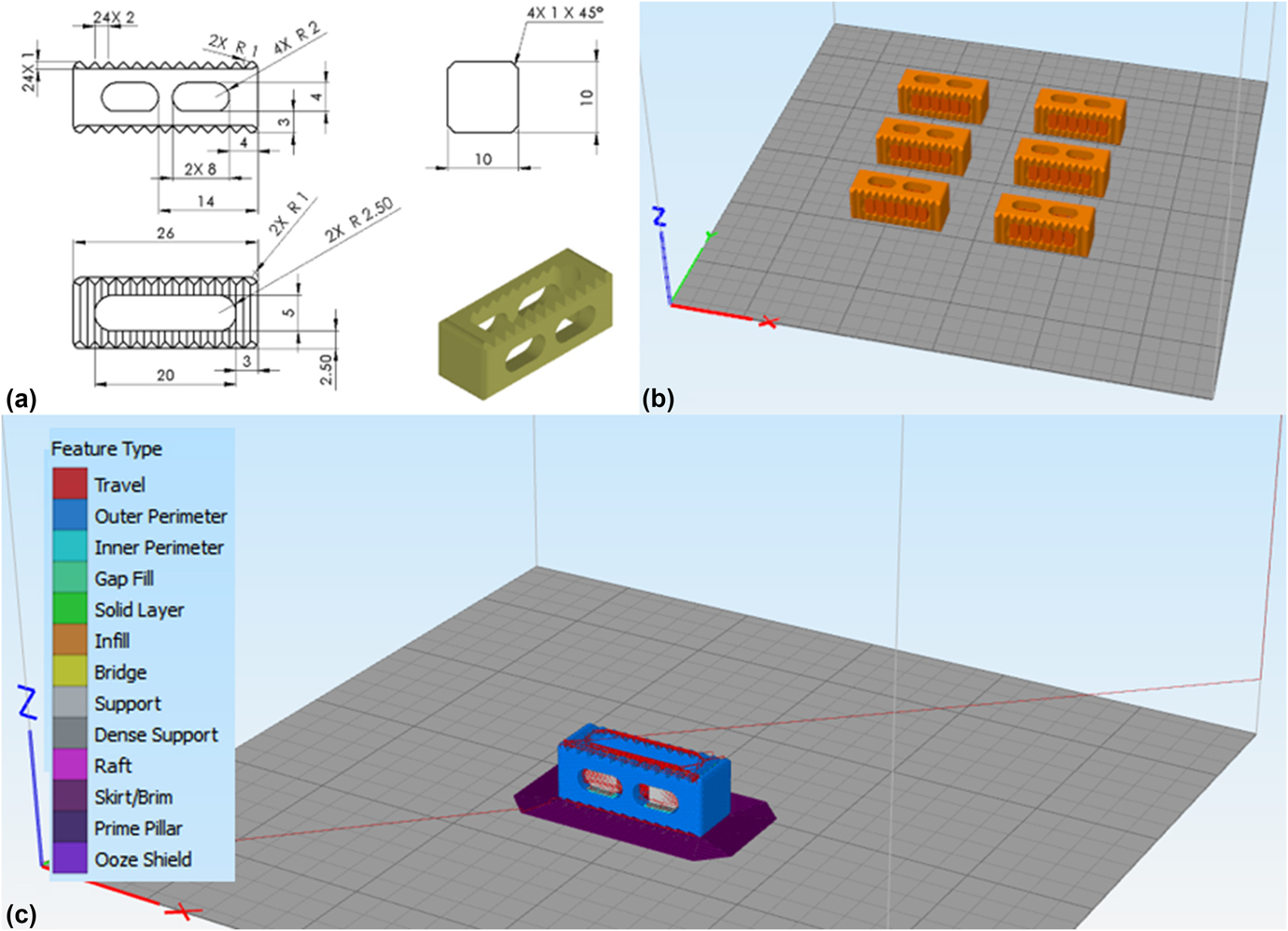
The lumbar cage design used in this study was developed as a reference for ASTM interlaboratory studies [Fig. 1(a)].25 The STL file of the cage was created from a 3D model drafted using commercially available software (SolidWorks 2016; Dassault Systèmes, Villacoublay, France). Simplify3D software (available commercially) was used to digitally slice the samples and create the g-code. A batch of six cages was printed on the heated bed. Temporary support structures of 3 mm were generated in the holes of both sides of the cages to ensure that the horizontal cage struts did not collapse during printing [Fig. 1(b)]. In addition, to increase the adhesion between the print object and the print bed, brims were added to the cages [Fig. 1(c)]. These support structures were subsequently trimmed from the cages after printing and before any mechanical or physical property testing.
CAD drawing (a) shows the design parameters for the cage used in this study. A batch of six cages was created with support structures on the heated bed (b) and g-code was created after the addition of the brims around the cages (c) on Simplify3D software.

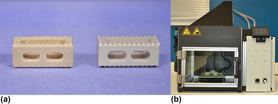
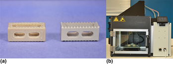
The professional 3D printer used in this study was Indmatec HPP 155/Gen 2, (Apium Additive Technologies GmbH, Karhlsruhe, Germany), which was designed specifically for PEEK FFF AM [Fig. 2(a)]. It has a print volume of 155 × 155 × 155 mm and the printing environment is thermally isolated inside an insulated build chamber. The nozzle diameter for the extruder was 0.4 mm. To increase the adhesion between the cages and the heated bed further, one layer of Dimafix® (DIMA 3D Printers, Valladolid, Spain) solution was applied onto the heated bed prior to printing.
Machined cages (a-right) were manufactured from the PEEK OPTIMA LT1 rod and FFF cages (a-left) were printed with the filament of PEEK OPTIMA LT1 and a customized PEEK printer (b).

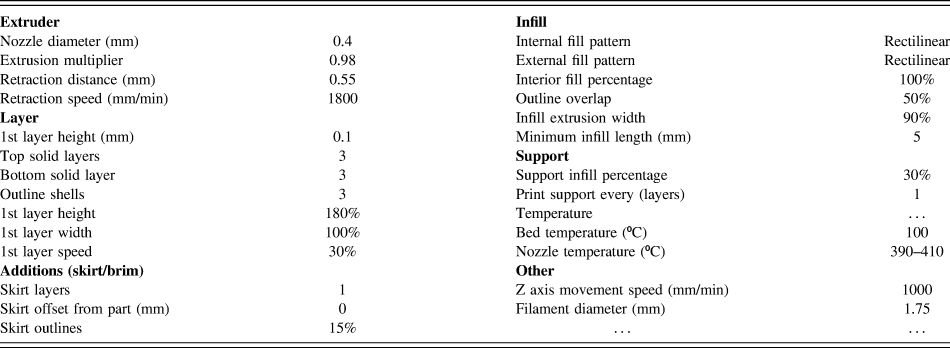
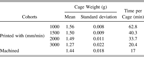
Printing conditions were kept same for all the cohorts (Table I), except for the printhead (extruder) nozzle X/Y axis movement speed, also referred as “printing speed.” Four printed cohorts were fabricated with 1000, 1500, 2000, and 3000 mm/min printing speeds using the PEEK OPTIMA™ LT1 filament [Fig. 2(b)]. The printing time and the filament usage for FFF cohorts were recorded (Table II). In addition to the printed cohorts, control samples were machined from the PEEK OPTIMA™ LT1 extruded rod [Fig. 2(b)].
Printing settings for FFF cages.

Manufacturing time and cage weight of cohorts depending on the manufacturing method.

B. Mechanical testing
Five samples from each cohort were tested under compression, compression–shear, and torsion according to the ASTM F207726 and in accordance with ISO 17025 quality system requirements.27 Tests were conducted on a MTS Mini Bionix 858 system (MTS Systems Corporation, Eden Prairie, Minnesota) equipped with calibrated load and displacement sensors. The load cell capacity was 15 kN for compression and shear tests, and the strain rate was chosen as 25 mm/min (as per ASTM F207726). The cell capacity for torque was 100 N m and torsion tests were conducted at 60°/min. Load–displacement and torque–angle curves were plotted from the data. Stiffness, ultimate displacement/angle, and ultimate load/torque values were calculated from the curves using a custom script in MATLAB 2016b (The MathWorks, Inc., Natick, Massachusetts), using the recommendations in ASTM F207726 as a guide.
C. Imaging
Prior to testing, three cages from each cohort were micro-CT scanned at 10 μm isotropic resolution using a Scanco μCT 80 (Scanco Medical, Brüttisellen, Switzerland). Both ends of the cage design, where it was solid cuboid, were defined as the regions of interest to obtain porosity measurements per cage. A control volume (5 × 5 × 2 mm3; limited by the standardized cage design) was created for the porosity calculations. Two control volume measurements were taken from the designated regions per cage to compare the average porosity and the pore size between the cohorts (n = 6 per cohort). The histogram of the grayscale values (which correspond with densities) resulting from the micro-CT scans appeared as two clear peaks [(one for the PEEK cages and the other for empty space (i.e., air)]. The threshold chosen for the segmentation threshold was the halfway point between the two peaks. Evaluations were conducted via Scanco software (Scanco Medical, Switzerland) on the control volumes. The evaluation for porosity percentage provided “solid volume/total volume” values. The porosity percentage of the control volumes were calculated using Eq. (1).
 $$1 - {{{\rm{volum}}{{\rm{e}}_{{\rm{solid}}}}} \over {{\rm{volum}}{{\rm{e}}_{{\rm{total}}}}}}\quad .$$
Moreover, the outcome from the evaluations for average pore size is a volume-based thickness. The software uses a volume-based local thickness algorithm which was introduced by Hildebrand and Rüegsegger.Reference Hildebrand and Rüegsegger28 After mechanical testing, the fracture surfaces of printed cohorts were imaged using light microscopy to view the crack morphology of different cohorts under the same loading condition. Crack and layer width were also calculated from the light microscopy images of the compression samples. Furthermore, detailed surface micrographs of printed cohorts were taken to analyze the porosity and the structure of the surface via scanning electron microscopy (SEM). Prior to SEM, cages were sputtered with platinum and palladium to achieve a conductive surface.
D. Level of crystallinity
X-ray diffraction (XRD) and Fourier transmission infrared spectroscopy (FTIR) were used to determine the degree of crystallinity of PEEK cages. Wide-angle X-ray scattering (WAXS) was determined as the scattering technique for XRD. For WAXS, two cohorts were created as top and bottom from printed cages according to the location where the samples were obtained. Three samples per cohort were evaluated. 1 mm thick samples were used for WAXS analysis. An internal plate was used to collect diffracted X-ray at a distance of 82 mm from the sample for 60 min. The internal plate was then read using RAXIA software to determine the diffraction pattern by plotting 2 theta (2θ) versus intensity. MagicPlot software (Magicplot Systems, LLC, Saint Petersburg, Russia) was used to fit Gaussian distributions and determine the area of the curve to each crystalline peak. The degree of crystallinity was calculated using Eq. (2).
 $${{{\rm{Are}}{{\rm{a}}_{{\rm{crystalline}}}}} \over {{\rm{Are}}{{\rm{a}}_{{\rm{amorphous}}}} + {\rm{Are}}{{\rm{a}}_{{\rm{crystalline}}}}}}\quad .$$
FTIR samples for printed cohorts were prepared from the body of the cages after dividing the cages into two to avoid any contamination of printing bed-PEEK adhesion material, whereas the surface was used for machined cohort (n = 9–14). FTIR measurements were collected with a Nicolet Continuum (Thermo Electron Corporation, Waltham, Massachusetts) and the parameters used were based on ASTM F2778.29 Crystallinity from FTIR data was also calculated using the crystallinity index and the equation provided in ASTM F2778Reference Hildebrand and Rüegsegger28 using a custom script in MATLAB 2016b.
E. Statistics
Distributions of data were first inspected for normality using the Shapiro–Wilk W test. Normal data sets were analyzed via ANOVA with a post hoc Dunnett’s test [pairwise ranking with a control (machined cages)]. The Kruskal Wallis test with a post hoc steel test [pairwise ranking with a control (machined cages)] was conducted for comparisons with non-normal data sets. The control group was designated as machined cage cohort. In addition, bivariate correlation analysis was performed using the Pearson correlation on the normal data sets, and with Spearman’s correlation on the non-normal data sets. Since the cracks were analyzed only on the printed cages, there was not a control group. For crack and layer width measurements, Kruskal Wallis test with a post hoc Dunn with Bonferroni correction was conducted for comparisons. Statistical analyses were performed using commercially available statistical software (JMP 11.0; SAS Institute Inc., Cary, North Carolina) with α = 0.05.
III. RESULTS
A. Mechanical testing
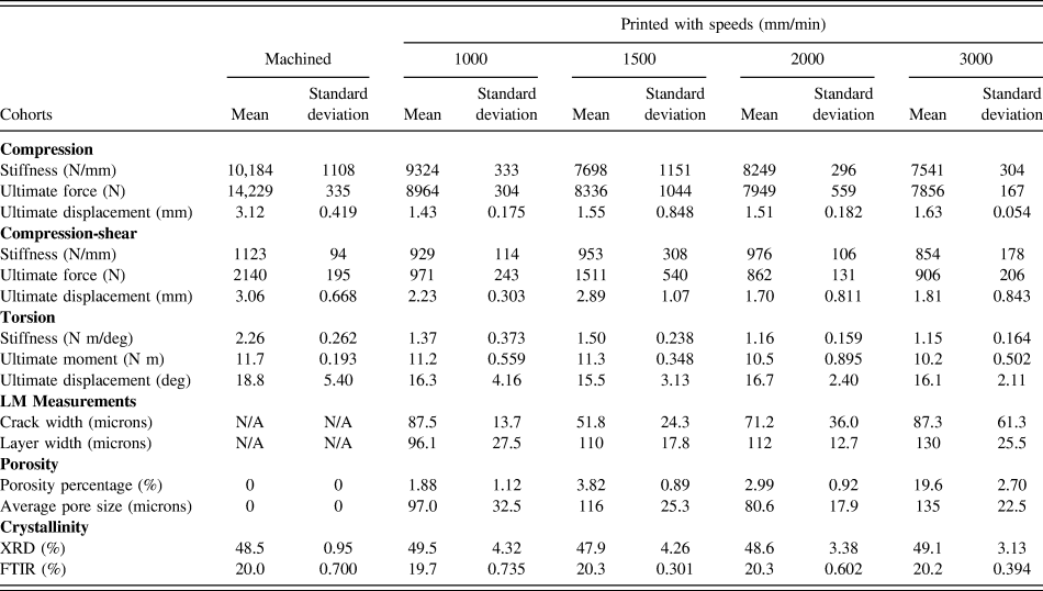
The stiffness of the printed cages achieved between 74 and 92% of the machined cages’ stiffness depending on the loading condition (Table III). Under compressive loading, cages printed with the slowest speed (1000 mm/min) were able to provide 91.6% of machined cage stiffness, and we did not observe a difference between the stiffnesses of the printed cages (P = 0.25). The bivariate analysis of speed versus stiffness showed that stiffness decreased significantly when the printing speed increased [Pearson correlation coefficient (PCC) = −0.58, P < 0.01]. Finally, machined cages were significantly stiffer than printed cohorts with 1500, 2000, and 3000 mm/min (P < 0.001, 0.002, and <0.001; mean difference = 2486, 1935, and 2643 N, respectively).
Metrics calculated in this study.

Under compressive–shear loading, we did not detect a difference in stiffness between printed cohorts and the machined cohort (P = 0.37). Printed cages showed similar stiffness compared to the machined cages and they were able to provide up to 87% stiffness of the machined cages. Printing speed did not significantly affect the stiffness of printed cohorts when compressive–shear loading was applied (PCC = −0.18; P = 0.47).
Under torsional loading, the printed cohort with 1500 mm/min was able to reach 67% of machined cages’ stiffness. However, machined cages were significantly stiffer than all printed cohorts (P = 0.04 for all tests; mean difference = 888, 757, 1103, and 1114 N mm/°, for the cohorts printed with 1000, 1500, 2000, and 3000 mm/min, respectively). The decrement in printed cohorts’ torsional stiffness due to printing speed increment was not significant (Rho = −0.37; P = 0.11).
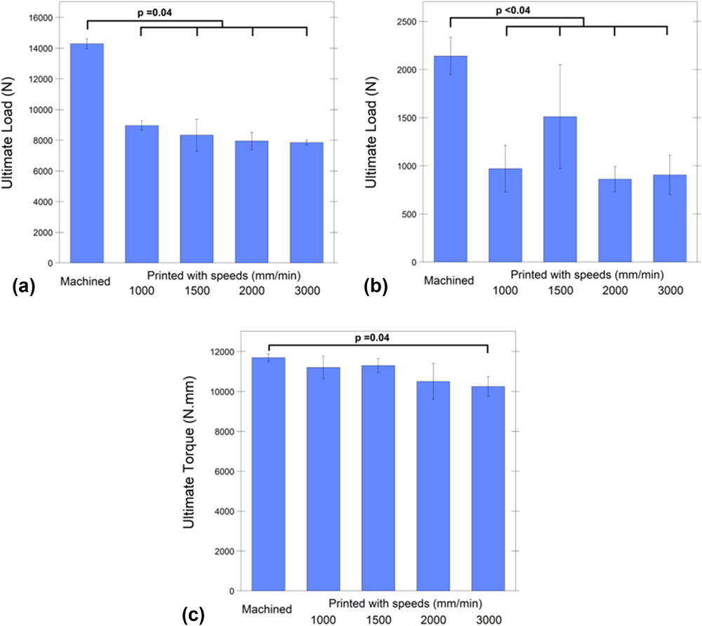
In addition to the stiffness, ultimate load/moment and ultimate displacement were compared among cohorts [compression, shear, or torsion, Fig. 3]. Under compressive loading, slowest printed cages were able to provide 63% ultimate strength of the machined cages [Fig. 3(a)]. However, machined cages’ ultimate load was significantly higher than all printed cohorts (P = 0.04 for all the comparisons; mean difference = 5336, 5964, 6351, and 6443 N, for the cohorts printed with 1000, 1500, 2000, and 3000 mm/min, respectively). The bivariate analysis revealed that the printing speed was inversely correlated with the ultimate load (Rho = −0.61, P = 0.005).
Under compressive loading, slowest printed cages were able to provide 63% ultimate strength of the machined cages (a). Under compressive-shear loading, the cohort printed with 1500 mm/min speed showed 71% ultimate load of the machined cages; however, they were both significantly lower than machined cages (b). Under torsional loading, cohorts printed with 1000, 1500, and 2000 mm/min showed comparable (92% on average) ultimate moment with the machined cages and with no significant differences (c).

When compressive–shear load was applied to the cages, the cohort printed with 1500 mm/min speed showed 71% ultimate load of the machined cages; however, it was significantly lower [P = 0.03; mean difference = 629 N; Fig. 3(b)]. Additionally, machined cages showed significantly higher ultimate load than the other printed cohorts (P < 0.001 for all tests; mean difference = 1169, 1279, and 1235 N for the cohorts printed with 1000, 2000, and 3000 mm/min, respectively). There was no correlation in ultimate load printing speed under shear (PCC = −0.24, P > 0.19).
Under torsional loading, cohorts printed with 1000, 1500, and 2000 mm/min showed comparable ultimate moment with the machined cages and with no significant differences [P = 0.18, 0.27, and 0.39, respectively; Fig. 3(c)]. The machined cages’ ultimate moment was only higher than the fastest cohort (3000 mm/min) (P = 0.04 and mean difference = 1448 N mm). The bivariate analysis verified that the ultimate moment reached under torsional loading was negatively correlated with the printing speed (Rho = −0.60; P = 0.005).
When ultimate displacement was compared between cohorts under compression, the machined cohort was displaced significantly more until it reached the ultimate load compared to printed cohorts with 1000, 2000, and 3000 mm/min (P = 0.04 for all tests; mean difference = 1.69, 1.61, and 1.49 mm). The only significant difference detected was between printed cohort with 1500 mm/min and machined cohort (P = 0.12 and mean difference = 1.57 mm). And there was not a significant correlation between the printing speed and ultimate displacement (Rho = 0.35 and P = 0.5).
Printed cohorts demonstrated similar ultimate displacement under compression–shear force compared to the machined cages (P = 0.08). Additionally, the printing speed was not correlated with ultimate displacement under shear force (PCC = −0.31; P = 0.199). Similarly, the printed cohorts’ angular displacement was not significantly different than machined cages (PCC = 0.02; P = 0.94). No significant difference was observed between the printed cohorts’ displacement under torsional load (P = 0.66) and no correlation was detected between the angular displacement of the cohorts and the printing speed (P = 0.94).
B. Imaging
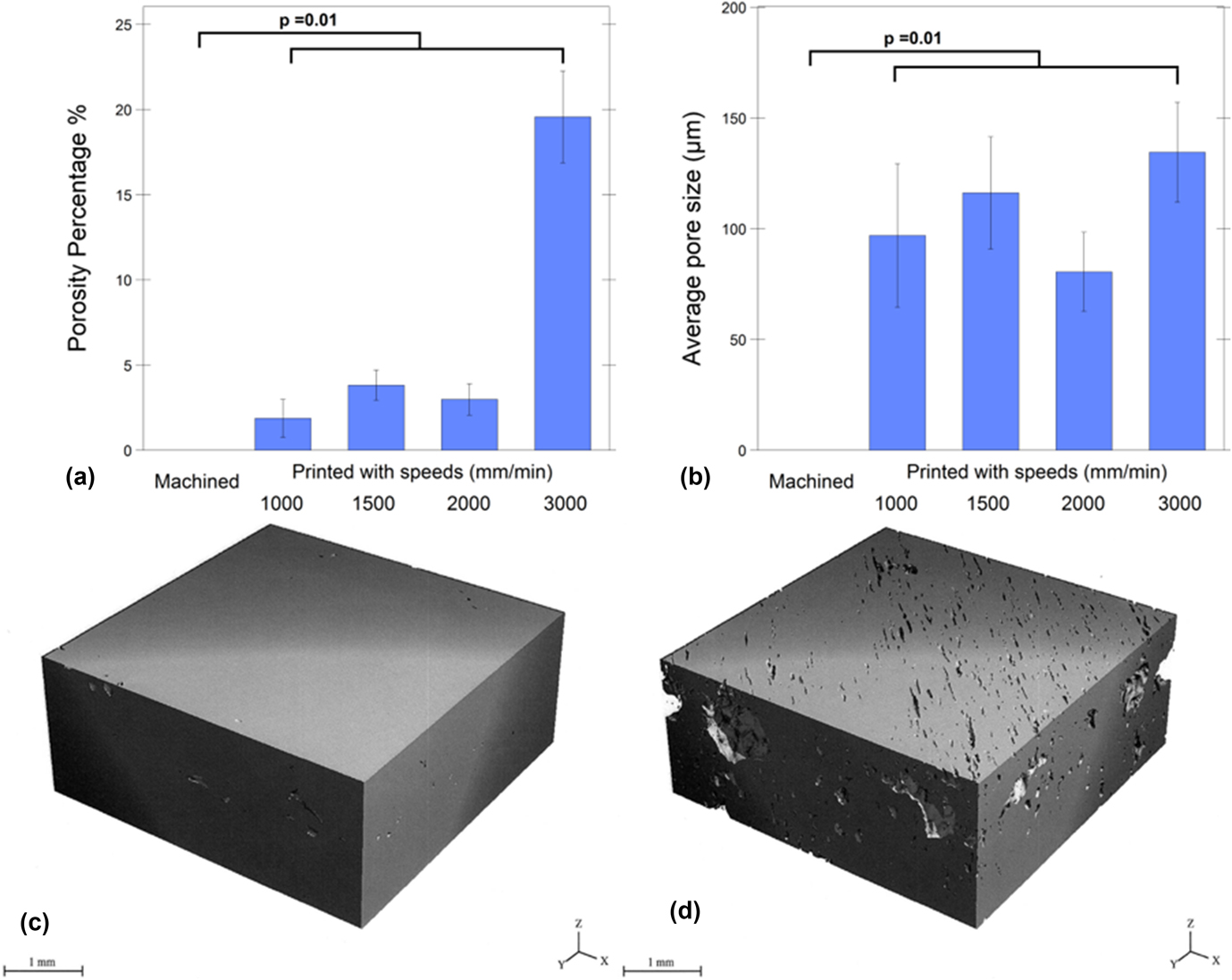
Based on the micro-CT scans, printed cohorts exhibited, on average, between 2 and 20% porosity [Fig. 4(a)]. There was a strong correlation between the printing speed and the porosity of the printed cages (PCC = 0.88; P < 0.001). As expected, there were no detectable pores (mean porosity = 0%) for machined cages, which was significantly lower than printed cages (P = 0.01 for all tests; mean difference = 1.88%, 3.82%, 2.99%, and 19.6%, for printed cohorts with 1000, 1500, 2000, and 3000 mm/min, respectively).
Porosity in cohorts. Increasing the printing speed increased the porosity of printed cages significantly (a). Mean porosity difference was 18% between the slowest printed (1000 mm/min) (c) and the fastest printed cohort (3000 mm/min) (d). Average pore sizes of printed cohorts were between 80 and 135 μm and there was not a significant correlation between printing speed and average pore size (b).

The average pore sizes ranged between 81 and 135 µm wide for all printed cohorts [Fig. 4(b)]. We did not observe a correlation between the printing speed and average pore size (PCC = 0.37; P = 0.08). The average pore size for machined cages was 0 µm and was significantly lower than all the printed cohorts (P = 0.01 for all tests; mean difference = 97, 116, 81, and 135 µm, for printed cohorts with 1000, 1500, 2000, and 3000 mm/min, respectively).
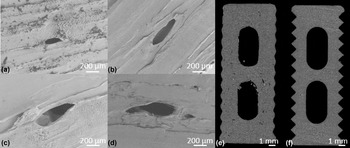
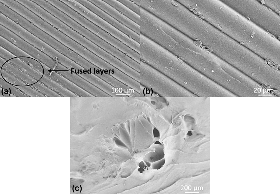
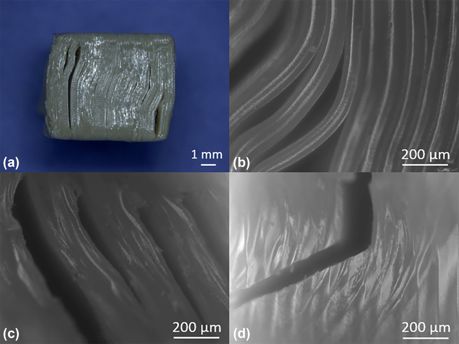
SEM images were used to visualize the pore structures on the cage surface (Fig. 5). It was observed from the SEM images that the printed cohorts had unfused layers which might be associated with weaker points for crack initiation (Fig. 6). The fracture surface morphology was the same for all printed cohorts under the same loading condition (Fig. 7). Under compression and shear, the cracks were observed parallel with the layers. On the other hand, under torsional loading, the crack started parallel with the layers and then changed the direction and became perpendicular to the layers.
Although average pore size did not significantly increase by increasing the printing speed, porosity was observed in all FFF cages (e) printed with 1000 (a), 1500 (b), 2000 (c), and 3000 (d) mm/min speed. However, both average pore size and porosity percentage of machined cages were not detected from micro-CT 3D scans (f).

Partial fusion of the layers (a) and unfused layers (b) both observed in a surface (a). Additional porosity might be caused by external factors such as nozzle removal from the print surface (c).

Under compressive (a and b) and shear loading (c) conditions, the cracks were aligned parallel with the layers. However, under the torsional loading condition, the crack initiated along the printed layers and it continued perpendicular to the printed layers (d).

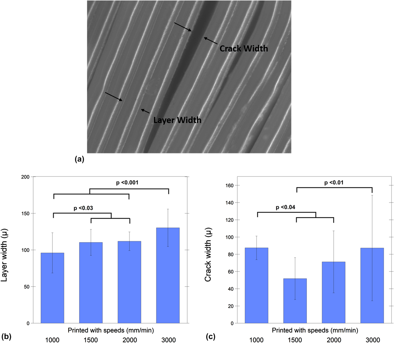
Additionally, the layer and crack width were calculated and analyzed (Fig. 8 and Table III). The bivariate analysis indicated that the layer width increased significantly when the printing speed was increased (Rho = 0.46 and P < 0.0001). Fastest printed (3000 mm/min) cohort’s layers were significantly wider than the other printed groups (P < 0.001 for all tests; mean difference = 34.2, 19.9, and 18.37 µm, for printed cohorts with 1000, 1500, and 2000 mm/min, respectively). Moreover, the slowest printed (1000 mm/min) cohort’s layer width was significantly smaller than the cohorts printed with 1500 and 2000 mm/min (P < 0.03 and mean difference = 14.3 and 15.8 µm, respectively).
Crack and layer width were measured from printed cohorts after compression testing (a). Increasing the printing speed caused a greater layer width (b); however, crack width was not significantly correlated with the print speed (c).

For crack width, on the other hand, there was no significant correlation due to speed increment (SCC = −0.12, P = 0.39). Nevertheless, the slowest printed (1000 mm/min) cohort’s crack width was significantly higher than the cohorts printed with 1500 and 2000 mm/min (P < 0.0001 and 0.04 and mean difference = 35.7 and 16.25 µm, respectively). Finally, the fastest (3000 mm/min) printed cohort demonstrated a significantly higher crack width than the 1500 mm/min group (P = 0.009 and mean difference = 35.5 µm).
C. Level of crystallinity
Both FTIR and XRD confirmed that crystallinity did not depend on the manufacturing method in PEEK cages. There was no significant difference detected between the printed cohorts and machined cohort crystallinity calculated via FTIR, (mean crystallinity ∼20%; P = 0.49, 0.98, 0.74, and 0.98 for printed cohorts with 1000, 1500, 2000, and 3000 mm/min, respectively, Table III). Additionally, we did not observe a correlation between the printing speed and the crystallinity measured using FTIR (PCC = 0.12 and P = 0.46). Similarly, XRD also did not show any significant differences between the printed and machined cohorts (P = 0.97, 1.0, 1.0, and 1.0 for printed cohorts with 1000, 1500, 2000, and 3000 mm/min, respectively). The average crystallinity calculated via WAXS was approximately 49% (Table III). Similar to FTIR, there was not a correlation detected between the printing speed and the crystallinity measured using XRD (PCC = 0.001 and P = 0.996). There was no significant difference in crystallinity detected between the top and bottom locations with reference to the heated bed of the printed cohorts via WAXS (P = 0.68).
IV. DISCUSSION
We present here a detailed structure–property investigation of FFF PEEK structural, load-bearing implants developed using a commercially available printer. The 3D-printed PEEK cages via FFF achieved between 63 and 92% strength of machined PEEK cages under different loading conditions. We would like to emphasize that these findings were obtained with the “as-printed” cages, without any subsequent post-processing such as annealing. The results of this study suggest that the optimum printing speed for FFF PEEK cages in the present configuration is between 1000 and 1500 mm/min. Our findings were explained by porosity of the cages, as documented by micro-CT evaluations and SEM images. We did not observe an association between the cage properties and crystallinity as a function of printing speed, further supporting the concept that print defects at the microscale, rather than crystalline morphology, are likely responsible for the differences between the FFF and machined PEEK cages.
Previous studies of FFF PEEK have shown mechanical property differences of FFF compared to other manufacturing methods.Reference Rahman, Letcher and Reese21 Cicala et al.Reference Cicala, Latteri, Del Curto, Lo Russo, Recca and Fare22 conducted tensile loading on the PEEK dog-bone specimen 3D printed by FFF and showed that FFF PEEK’s tensile strength was 77% of the injection molded PEEK. Similarly, Rahman et al.Reference Rahman, Letcher and Reese21 provided a range of injection molded PEEK’s tensile strength, where their FFF PEEK results performed from 33 to 97%. As an alternate AM method, PEEK manufactured via SLS was referred to have lower strength than injected molded PEEK as well.Reference Schmidt, Pohle and Rechtenwald17 Berretta et al.Reference Berretta, Evans and Ghita18 tested the tensile strength of their dog-bone PEEK specimen produced by SLS, which were around 60% of the PEEK’s tensile strength.30
While taking the reported decrease caused by FFF from the literature into consideration, it must be noted that our results are applied on the spinal cages tested under compressive loading conditions rather than tension. Mechanical properties of FFF PEEK cages were compared as reference to machined cage results which were within the reproducibility limit of ASTM standards.25 FFF cages exhibited a compressive strength of ∼8 kN, which is less than the machined PEEK cages but in excess of the load expected for cages under in vivo loading.Reference White and Panjabi31 The compressive strength of human thoracolumbar vertebrae ranges from about 2000 N for specimens having low bone density and small cross-sectional areas to about 8000 N for specimens having high bone density and large cross-sectional areas.Reference Keaveny, Buckley, Kurtz and Edidin32 Similarly, Wilke et al.Reference Wilke, Neef, Caimi, Hoogland and Claes33 measured in vivo lumbar disc pressure in common activities which was between 180 and 4140 N. Although the compressive–shear and torsional strength were lower for FFF cages than that for machined cages, they were above the axial compression–shear and rotation limits defined for a spinal unit.Reference Melkerson, Kirkpatrick and Griffith34
The difference in mechanical properties between FFF versus machined PEEK cages can be explained, at least in part, both by the layer adhesion and porosity of the printed cages. Crack visualization indicated the importance of the layer adhesion for FFF cages. This strengthens the idea of layer-to-layer intersection line being the stress point since the cracks observed along with the layers.
Micro-CT scanning was previously designated for characterization of porosity in parts printed via FFF.Reference Chen, Lo, Chen and Shih35 In our study, the FFF cages’ (printed with slowest speed) average porosity calculated from micro-CT scans of control volume was 2%. Often the cause of porosity is explained by the entrapped micro-air bubbles in the filament and voids which became pores during the FFF process.Reference Vaezi and Yang20 Vaezi et al.Reference Vaezi and Yang20 stated that high level of porosity (38%) played a role in reduction of mechanical properties for their porous PEEK samples and showed that even printing with 100% infill they encountered 14% porosity of FFF PEEK samples. Cicala et al.Reference Cicala, Latteri, Del Curto, Lo Russo, Recca and Fare22 also emphasized the need of optimization for FFF PEEK by decreasing pore formation during the printing process.
The reason why slower speeds were suggested for FFF of PEEK is the association between printing speed and porosity. The printing speed had a great impact on the printed cages’ porosity such that it increased the porosity from 2 to 4% (slower speeds) to 20% (fastest speed).
Considering the fact that the printhead’s movement pattern remains the same regardless of the printing speed, increasing the printhead’s speed redundantly might have caused an imperfect filament-to-filament bonding, which could increase the porosity and cause an overall reduction in mechanical properties. In the same manner, Vaezi et al.Reference Vaezi and Yang20 associated the porosity found in PEEK samples with 100% infill with the formation of air gap between deposited filaments within layers. Additionally, it was emphasized by the previous studies that the influence of filament-to-filament bonding is more crucial than the strength of the filament itself for 3D-printed parts via FFF.Reference Rybachuk, Alice Mauger, Fiedler and Öchsner36,Reference Sung-Hoon, Michael, Dan, Shad and Paul37 Thus, in addition to diminishing entrapped microbubbles in the filament prior to printing, a good filament-to-filament bonding must be considered to reach the optimum structural integrity under load.
Furthermore, it was confirmed that the FFF process did not influence the cages’ crystallinity. It is well known that the crystallinity of PEEK has a sufficient influence in its mechanical properties.Reference Sobieraj, Rimnac and Kurtz38 The FFF process did not change the crystallinity of PEEK cages compared to the extruded rod, which were in accordance with the literature.Reference Jaekel, Medel and Kurtz39,Reference Jaekel, MacDonald and Kurtz40
Several limitations to the current study can be acknowledged here. The printing speeds used in this study are applicable to this printer and extruder configuration, and changes in this configuration may impact the porosity in a different manner than observed here. In the current study, cages were also tested “as-printed”, without any post-processing such as annealing which will be investigated in future research. Finally, the mechanical strength of the cages was evaluated under static loading conditions. Thus, future studies should investigate the fatigue behavior of printed cages compared to machined cages.
V. CONCLUSIONS
The results suggest that without any additional influence on 3D printing such as ambient parameter control or post-processing, FFF 3D-printed cages are already able to provide sufficient strength for lumbar cage applications. It also indicates the importance of printing parameters such as printing speed to avoid porosity which may improve the mechanical properties of printed cages. Our findings are important steps toward evaluating this novel 3D printing manufacturing technique for PEEK implants.
Supplementary Material
To view supplementary material for this article, please visit https://doi.org/10.1557/jmr.2018.178.
ACKNOWLEDGMENTS
This study was supported by NIH-R01 AR069119. We would like to thank Invibio for donating the medical grade PEEK derived filament and extruded rod stock used in the experiment. We would also like to thank Apium for their helpful advice and fruitful discussions.