Introduction
Organic light-emitting diode (OLED) has caused the extensive attention of the scientific community since Tang et al. prepared an OLED with three layers of cathode, anode, and luminescent layer (8-hydroxyquinoline) with good luminous efficiency, excellent film formation, and good flexibility in 1987 [Reference Tang and VanSlyke1]. OLEDs have the advantages of high response speed, wide visibility, low cost, low power consumption, and flexible display, making them widely applied to display fields such as mobile phones, notebooks, televisions, and dashboards [Reference Adachi, Tokito, Tsutsui and Saito2, Reference Burroughes, Bradley, Brown, Marks, Mackay, Friend, Burns and Holmes3, Reference Tao, Suzuki, Wada, Suzuki and Miyata4, Reference Xiao, Chen, Brown, Bo, Luo, Kong, Gong and Kiod5].
In OLEDs, the performance of luminescent materials is crucial. It affects the fabrication of efficient and stable OLEDs. In addition, it is also helpful to simplify its configuration and lower the construction costs [Reference Li, Ma, Tang, Lee and Lee6, Reference Li, Liu, Li, Lee, Kwong and Lee7, Reference Bernius, Inbasekaran, O’Brien and Wu8]. However, the luminescence of the traditional π-conjugated fluorophores weakened obviously in solid state that is known as aggregation-caused quenching (ACQ) effect, which has been proved a thorny obstacle to the fabrication of efficient OLEDs [Reference Thomas, Joly and Swager9, Reference Chiang, Tseng, Chen, Hsu and Shu10, Reference Wang, Zhao, Dou, Sun, Xu, Ye, Zhang, Jiang, Li and Wang11, Reference Grimsdale, Chan, Martin, Jokisz and Holmes12, Reference Liu, Lam and Tang13].
In 2001, Tang’s group discovered an interesting phenomenon: compound 1-methyl-1,2,3,4,5-pentaphenylsilole has a weak emission in dilute solution, but becomes highly emitted in the aggregated state. They termed this novel phenomenon as aggregation-induced emission (AIE) [Reference Luo, Xie, Lam, Cheng, Chen, Qiu, Kwok, Zhan, Liu, Zhu and Tang14], which was opposite to ACQ effect exactly. Then, they confirmed that the restriction of intramolecular motion (RIM) was the primary reason of AIE effect [Reference Chen, Xu, Ouyang, Tang and Cao15, Reference Leung, Xie, Yuan, Liu, Wu, Peng, Miao, Lam and Tang16, Reference Hong, Lam and Tang17, Reference Mei, Hong, Lam, Qin and Tang18, Reference Wang, Zhao, Lam and Tang19] in the aggregates after sufficient experimental and theoretical researches. This can be described as AIE molecules usually contain a structure with molecular rotors. In the excellent solvent, the excited state energy of the molecule is consumed by the motion of the rotor, and the energy is rapidly attenuated without emission. Conversely, in the aggregate state, the interaction between the molecules of the AIE limits the motion of the rotor, causing the molecules to decay through the radiating channel.
Based on RIM mechanism, Tang’s group has reported a variety of skeleton structures with AIE property successively, which laid a solid foundation for the development of AIE materials [Reference Zhao, He and Tang20, Reference Liang, Liu and Tang21, Reference Kwok, Leung, Chris, Lam and Tang22, Reference Mei, Hong, Lam, Qin, Tang and Tang23, Reference Hu, Lelson and Tang24, Reference Dong, Li, Zhao, Dong and Tang25, Reference Ding, Li, Liu and Tang26, Reference Zhao, Lam and Tang27, Reference Zhao, Lam and Tang28, Reference Qin, Lam and Tang29, Reference Hong, Lam and Tang30, Reference Hong, Lam and Tang31]. Li’s group obtained a series of efficient blue–green light emitting materials by modifying the framework of thiol-ol and tetraphenylethylene simply [Reference Huang, Sun, Chen, Tang, Li, Ma and Li32, Reference Huang, Sun, Yang, Tang, Li, Ma and Li33, Reference Yang, Sun, Huang, Li, Peng, Tang, Dong, Ma and Li34]. Chi’s group conducted abundant researches on triphenylethylene structure and synthesized various blue–green and red light emitting materials with AIE property [Reference Yang, Chi, Yu, Zhang, Chen, Xu, Liu, Zhang and Xu35, Reference Li, Chi, Xu, Zhang, Yang, Li, Liu, Zhang and Xu36, Reference Li, Chi, Zhang, Xu, Liu, Zhang and Xu37]. Ma’s group reported some AIE materials with high-efficient blue luminescence performance [Reference Tang, Yao, Liu, Shen, Zhang, Zhang, Lu and Ma38]. In addition, other groups have also done a lot of research work in this field. Recently, Tang’s group developed a series of AIE luminogens consisting of tetra-/tri/-phenylethene moieties and systematically investigated their photoluminescent and electroluminescent properties [Reference Shi, Xin, Gu, Zhang, Peng, Chen, Lin, Zha and Tang39, Reference Dong, Li, Shi, Cheng, Roose and Tang40, Reference Shi, Zhang, Gui, Wang, Fang, Zhao, Chen and Tang41, Reference Dong, Wang, Gui, Shi, Cheng and Tang42, Reference Shi, Wang, Qin, Gui, Zhang, Fang, Chen and Tang43, Reference Chen, Lin, Peng, Nie, Zhuang, Shen, Ding, Huang, Hu, Chen, Huang, Qin, Zhao and Tang44, Reference Li, Zhuang, Lin, Wang, Shen, Xiong, Wang, Chen, Zhao and Tang45, Reference Shi, Li, Xin, Fang, Roose, Peng, Chen and Tang46].
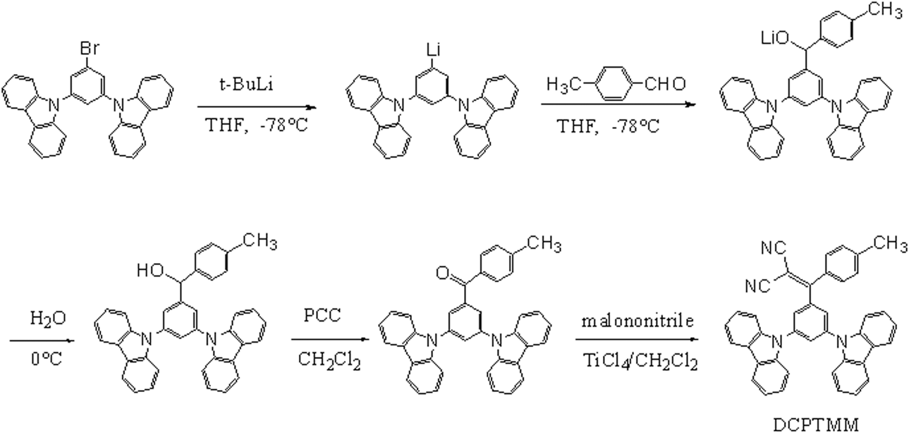
In view of above-mentioned, in here, we reported a new AIE compound, 2-((3,5-di(9H-carbazol-9-yl)phenyl)(p-tolyl)methylene)malononitrile (DCPTMM), which was designed and synthesized by combining the phenylmethylene group with AIE effect, the carbazole group with hole transport property, and the malononitrile group with electron transport property. The synthetic route is shown in Scheme 1. The structure was studied by 1H NMR, 13C NMR, high-resolution mass spectrum, and X-ray diffraction (XRD). The thermal stability and photophysical properties are characterized by various analytical methods. Finally, we constructed nondoped device with DCPTMM as the luminescent layer and measured the device performance such as turn-on voltage, maximum brightness, maximum current efficiency, and maximum quantum efficiency.
Synthetic route of DCPTMM.

Results and discussion
Synthesis and characterization
As shown in Scheme 1, the target compound (DCPTMM) was synthesized by multistep reaction. First, the key intermediate compound (1) was synthesized by a series of multistep reactions including substitution, hydrolysis, and oxidation based on 9,9-(5-bromo-1,3-phenyl) bis-9H-carbazole, t-BuLi, and 4-Bromobenzaldehyde with 67% yield. The structure of compound (1) was confirmed by 1H NMR. And then, DCPTMM was synthesized by reacting compound (1) with malononitrile in the condition of TiCl4 as catalyst in 45% yield. The structure of DCPTMM was completely characterized by 1H NMR, 13C NMR, MS, single crystal XRD, and powder XRD. The XRD pattern indicates that the powder is completely crystals. These data are placed in electronic supplementary information (ESI). DCPTMM presents excellent solubility in common organic solvents such as toluene, dichloromethane, chloroform, and tetrahydrofuran, but is insoluble in water and methanol.
Thermal properties
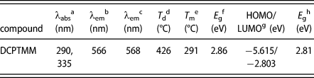
The stability of the compound determines whether it is suitable for OLEDs as excellent luminescent material. To clarify the stability of DCPTMM, its thermal and morphological properties were tested by thermogravimetric analysis (TGA) and differential scanning calorimetry (DSC) under nitrogen atmosphere. The test temperature of TGA is from room temperature to 800 °C, and the heating speed is 10 °C/min. The thermal stability curve is shown in Fig. S1 (ESI). As can be seen from the Fig. S1, DCPTMM has a relatively high decomposition temperature (decomposition temperature is the temperature at which the initial weight loss is 5%) of 426 °C. The test temperature of DSC is from 40 to 400 °C, and the heating speed is also 10 °C/min. The curve of DSC measurement is shown in Fig. S2 (ESI). As shown in Fig. S2, the twisted molecule also possesses good morphological stability, as confirmed by its high melting temperature (T m) of 291 °C. The data are summarized in Table I. The characterization results of TGA and DSC show that DCPTMM has good thermal and morphological stability, which can satisfy the process of vacuum deposition and operational stability of the OLED.
Physical properties of DCPTMM.

a Measured in THF.
b Measured in THF:H2O (1:90).
c Measured in films.
d Obtained from TGA.
e Obtained from DSC.
f Calculated from the absorption edge, E g = 1240/λonset.
g Obtained from DFT calculations.
h Obtained from DFT calculations, E g = LUMO − HOMO.
Photophysical properties
The photophysical properties were investigated by UV-vis absorption and fluorescence emission (the excitation wavelength is 360 nm). As is shown in Fig. S3 (ESI), the UV-vis absorption spectrum of DCPTMM in THF solvent (1.0 × 10⁻⁵ M) shows two absorption bands at 267–309 nm and 309–375 nm, respectively. The absorption peak at 290 nm is originates from the π–π* transition of the molecular skeleton and the absorption peak at 335 nm is generated by the π–π* transition of the intramolecular charge transfer (ICT) from carbazole to malononitrile group. Its optical energy band gap calculated from the absorption band edges of the UV-vis absorption spectrum is 2.86 eV. As shown in Fig. S4 (ESI), the fluorescence emission spectrum of DCPTMM has a relatively weak emission (1.0 × 10⁻⁵ M) in the THF solvent with emission peaks of 432 nm.
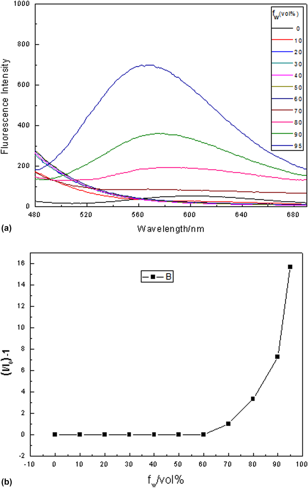
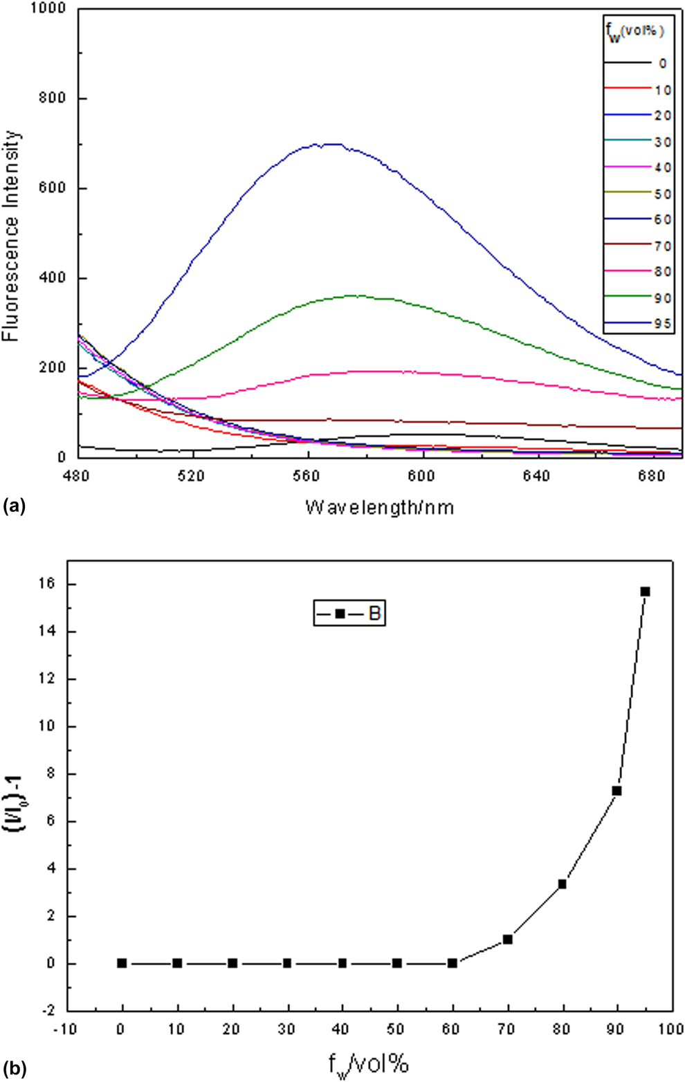
To further study the emission behavior of DCPTMM in aggregated state, its emission intensities in THF/water mixtures with different water fractions (f w) were tested. Herein, THF and water act as the solvent and nonsolvent, respectively. The test results are illustrated in Fig. 1. As shown in Fig. 1, DCPTMM emits a weak blue light in pure THF solution. The emission intensity in the mixed solvent is almost the same as in pure THF when the f w is less than 60%. When f w > 60%, the emission intensity start to rise, indicating the formation of nanoaggregates. The emission intensity achieves a maximum when f w reaches to 90% (566 nm). Besides, nanoparticles with a diameter of about 20–40 nm are clearly observed by scanning electron microscope (SEM) images (Fig. S5) (ESI). The results show that DCPTMM has obvious AIE characteristic, which can be contributed to the RIM process in the formation of aggregation. All photophysical data are collected in Table I.
PL spectra of compound in THF-water mixtures with various water contents (the excitation wavelength is 360 nm).
X-ray single crystal structure and AIE mechanism
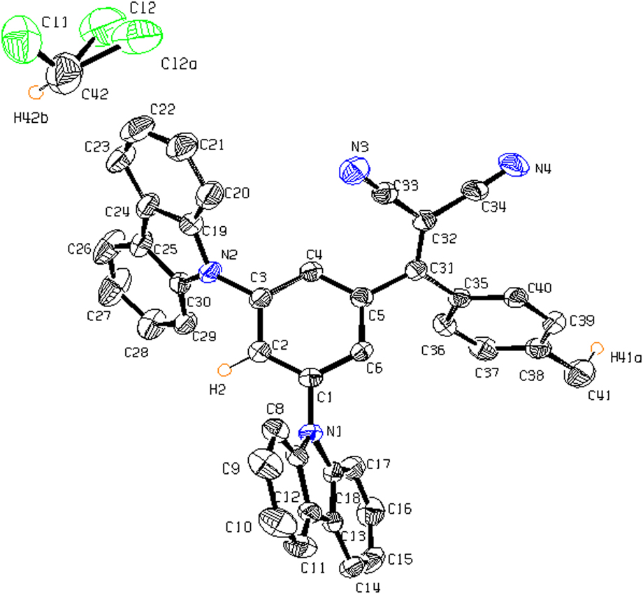
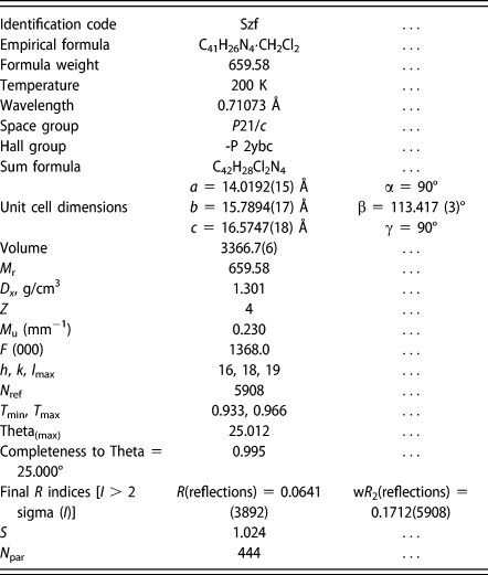
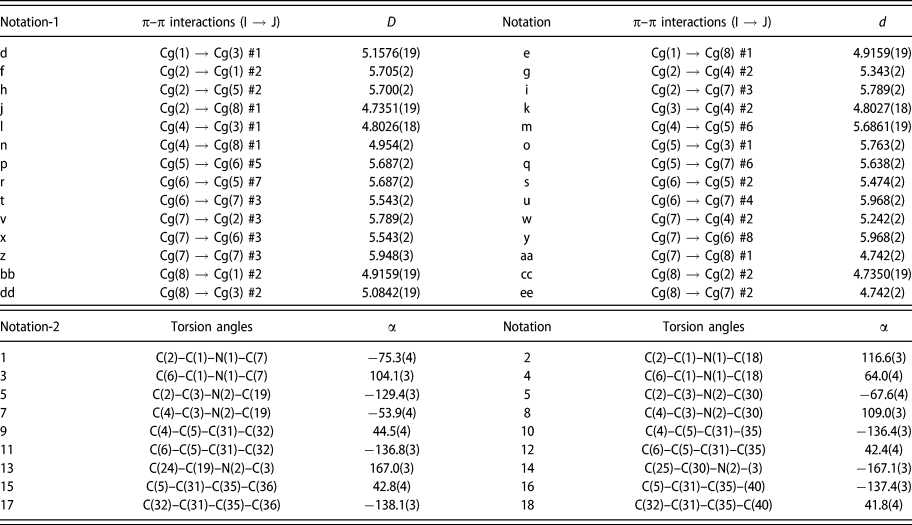
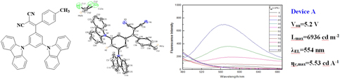
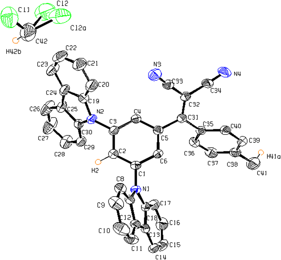
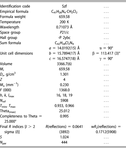
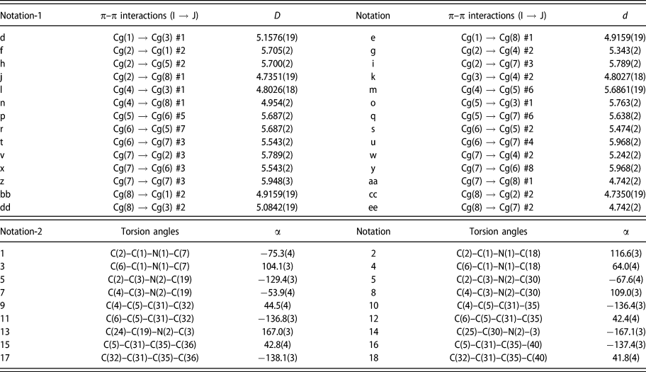
The study of X-ray single crystal structure is an effective means to reveal the correlation between molecular structure and properties. Single crystal of DCPTMM was obtained by slow diffusion in CH2Cl2–MeOH solvent system. The single crystal structure is cocrystallized with solvent CH2Cl2 at 1:1 ratio. The individual ORTEP structure is shown in Fig. 2. The single crystal study reveals that the crystal of DCPTMM belongs to monoclinic space group P21/c with Z = 4. The crystal structure data are put in Table II. The intramolecular torsion angels and intermolecular π–π distances of the aromatic rings are presented in Table III. As are shown in Table III, the intramolecular torsion angels of the aromatic rings confirm the strongly twisted conformation. As displayed in Fig. 2, DCPTMM employs a propeller-type conformation with two carbazole rings and one phenyl(p-tolyl) methylene malononitrile group attached to the m-position of the central phenyl ring. Such a twisted conformation is beneficial to generate AIE effect because this configuration can support the intramolecular movement of molecules in solution leading to poor fluorescence, restrict the intramolecular movement of molecules, and prevent the formation of π–π stacking of molecules, which have been further investigated with the PLATON calculations. These two effects resulted in the AIE performance of the compound. The results of PLATON calculation show that the distances between all the aromatic rings of DCPTMM ranged between 4.73 and 5.96 Å (Table III), which means there are no classical π–π interactions can be observed between adjacent molecules in these crystals [47].
The individual ORTEP structure.
Crystal data in the title compound.
π–π interactions and torsion angles in the title compound (Å,°).
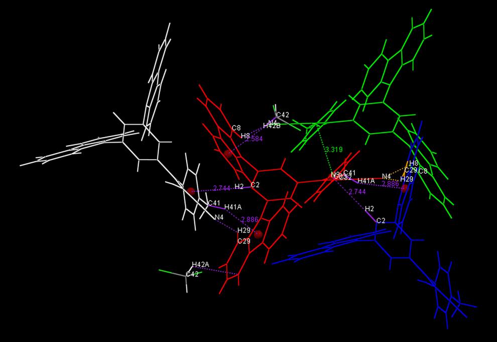
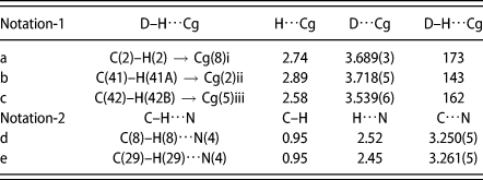
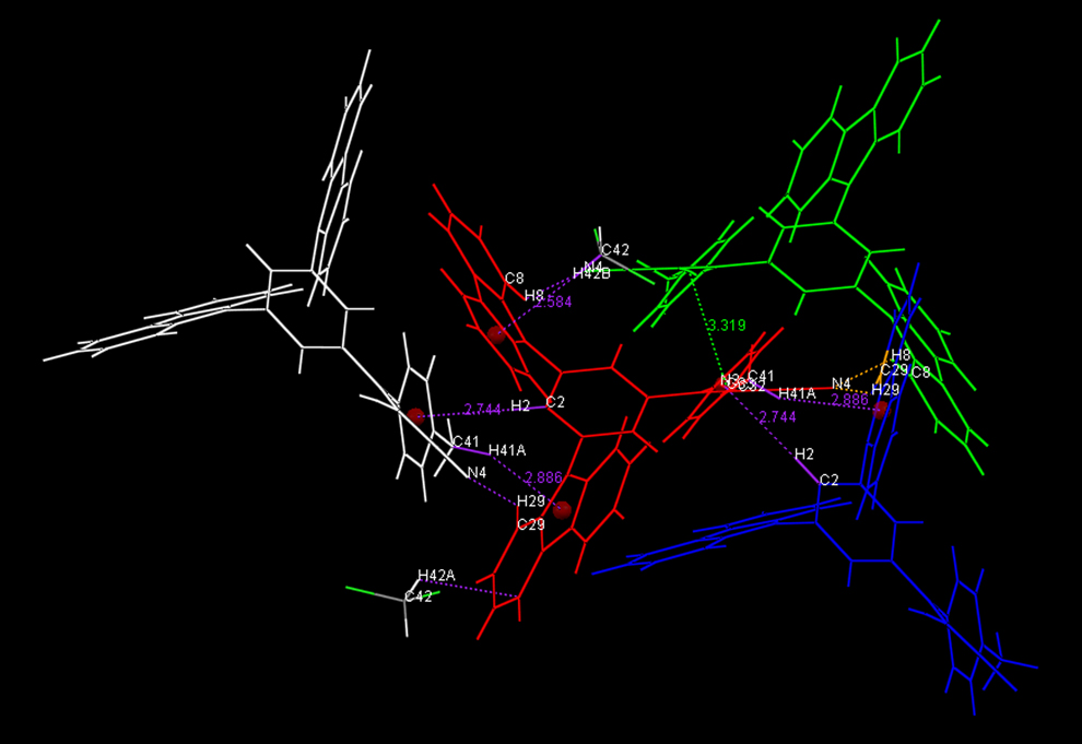
As showed in Fig. 3, in the crystal packing structure of DCPTMM, one DCPTMM molecule interacts with its three identical adjacent molecules and an adjacent solvent (CH2Cl2) molecule by means of five different kinds of C–H⋯π and/or C–H⋯N bonds. The four identical molecules of red, blue, purple, and white are identified as A, B, C, and D molecules, respectively. The solvent (CH2Cl2) molecule is identified as E molecule. The intermolecular hydrogen bonds are listed in Table IV. As showed in Table IV, the hydrogen bonds of C(2)–H(2)⋯Cg(8)(C35–C36–C37–C38–C39–C40) and C(29)–H(29)⋯N(4) with distance of 2.74 and 2.45 Å are formed between the molecule A (in the middle position) and the B molecule. One carbazole group and the intermediate phenyl ring in the A molecule are firmly fixed by these two hydrogen bonds. The benzyl group of A molecule is fixed by a C(41)–H(41A)⋯Cg(2)(N(2)–C19–C24–C25–C30) bond with the distance of 2.89 Å and a C(8)–H(8)⋯N4 bond with the distance of 2.52 Å formed by A molecule and C molecule. The carbazole group of A molecule is fixed by C(8)–H(8)⋯N4 bond with the distance of 2.52 Å formed by the A and D molecule. The E molecule and the A molecule form a C(42)–H(42B)⋯Cg(1)(N1–C7–C12–C13–C18) bond with the distance of 2.58 Å. This bond locks the benzene ring in the carbazole group of the A molecule. The formation of multiple hydrogen bonds between the A molecule and the adjacent molecules can help lock the molecular motion in the crystal lattice and reduce the nonradiative deactivation of the excitations, which contribute to the AIE effect of DCPTMM.
The crystal packing structure of DCPTMM.
Intermolecular hydrogen bonds (C–H⋯π and C–H⋯N) in the crystal packing of DCPTMM.

Theoretical calculation
For understanding the relationship between the emission and the structure well, the density functional theory (DFT) was conducted by the B3LYP/6-31G(d) level in the Gaussian 09 program (American Gauss Corporation) to optimize the molecular structure of DCPTMM. As shown in Fig. S6, the optimized structure of the molecule exhibits a propeller-type configuration, which is consistent with the result of the crystal structure. Such a structure can effectively attenuate the π–π interaction between the aromatic rings. The highest occupied molecular orbital (HOMO) is mainly distributed on the carbazole and the benzene ring in the middle position. The lowest occupied molecular orbital (LUMO) is mainly distributed over the ethylene, the malononitrile and the benzene ring on the other side. There is a certain degree of overlap on the benzene ring in the middle position between the electron cloud of HOMO and LUMO, which facilitates charge transfer within the molecule. The calculated energy gap of HOMO and LUMO is in good agreement with the experimental one obtained from the UV-vis absorption spectra. The relevant data are also listed in Table I.
Electroluminescent properties
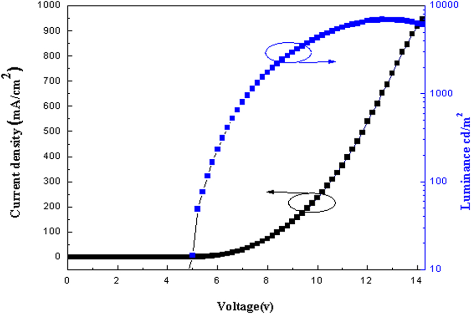
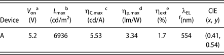
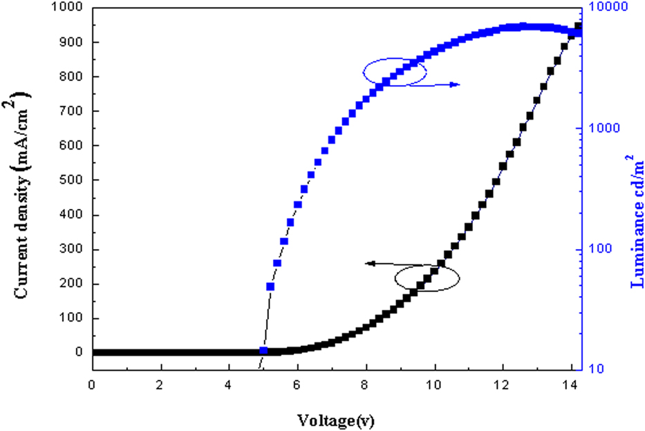
To appraise the performance of DCPTMM as a light-emitting material in electroluminescent device, the nondoped OLED was fabricated and tested with conformation of ITO/HATCN (20 nm)/NPB (40 nm)/DCPTMM (20 nm)/TPBI (40 nm)/LiF (1 nm)/Al (100 nm). ITO was used as an anode, dipyrazino[2,3-f:2′,3′-h]quinoxaline-2,3,6,7,10,11-hexacarbonitrile (HATCN) as a hole-injection layer, N,N-bis(1-naphthyl)-N,N-diphenylbenzidine (NPB) as a hole-transfer layer, 1,3,5-tris(N-phenylbenzimidazol-2-yl)benzene (TPBi) as an electron-transport/hole-block layer, LiF as an electron-injection layer, and Al as a cathode. As shown in Fig. S7, the electroluminescence (EL) spectrum of device A presents a maximum emission peak of 554 nm with Commission International de l’Eclairage (CIE) coordinates of (0.41, 0.54), showing DCPTMM emit greenish yellow light. The CIE chromaticity coordinates of device A is displayed in Fig. S8. The EL emissions spectrum of device A is slightly blue-shifted compared to ones of photoluminescence in the film and the 95% aqueous solution, which demonstrate that the EL emissions originate from the amorphous emitting layer. The current density–voltage–luminance curves and the current efficiency–current density curves of device A are depicted in Fig. 4. The EL data are summarized in Table V. As shown in Table V, device A exhibited valuable EL performances with a turn-on voltage of 5.2 V, a maximum luminous efficiency of 5.53 cd/A, and a maximum brightness of 6936 cd/m2. It is known from the curve of Fig. 4 that the current density and brightness increase with the increase of voltage, indicating that DCPTMM has excellent charge injection and transport properties.
The current density–voltage–luminance curves.
EL properties of device A.

a Turn on voltage at a brightness of 1 cd/m2.
b Maximum luminance.
c Maximum current efficiency.
d Maximum power efficiency.
e External quantum efficiency.
f Electroluminescence peak.
Conclusions
A novel compound (DCPTMM) containing structural units of diphenylethylene, carbazole, and malononitrile is designed and synthesized in this project. DCPTMM has good thermal stability and distinct AIE property. In individual structure of crystals, this molecule is monoclinic system with space group symbol P21/c and presents a twisted propeller-type structure. In packing structure of crystals, multiple types of hydrogen bonds (C–H⋯π and C–H⋯N) are formed between adjacent molecules and there is no π–π interaction between the aromatic rings, which is the main reason for the formation of AIE. Finally, we used this new AIE material as the luminescent layer to fabricate a nondoped OLED. Test results of the device show that the nondoped OLED has relatively good performance with a turn-on voltage of 5.2 V, a maximum current efficiency of 5.53 cd/A, and a maximum brightness of 6936 cd/m2.
Experimental section
Synthesis
Unless stated, all relevant chemicals and common organic solvents were obtained from commercial suppliers and were used without further purification. Tetrahydrofuran (THF) was distilled with a sodium and benzophenone mixture under dry nitrogen atmosphere. All the reactions were conducted under a nitrogen atmosphere.
Synthesis and characterization of (3,5-di(9H-carbazol-9-yl)phenyl)(p-tolyl)methanone (1)
Under nitrogen atmosphere, 5.3 g of 9,9′-(5-bromo-1,3-phenylene)bis(9H-carbazole) and 70 mL of dried THF were placed in a round bottom flask. And 18.5 mL of t-BuLi was dropped by a syringe into the system where the temperature of the mixture was lowered to −78 °C. The mixture was first incubated at −78 °C for 1 h and then warmed to room temperature and reacted for 5 h. Thereafter, the reaction mixture was again cooled to −78 °C, and 4 mL of p-methylbenzaldehyde was added dropwise to the mixed solution. Subsequently, the mixture was stirred at −78 °C for 1 h and then stirred at room temperature for 12 h. Ice water (50 mL) was added to the mixed solution to quench the reaction, followed by hydrolysis for 2 h. After completion of the above reaction, the resulting mixture was extracted twice with CH2Cl2, washed three times with water, and dried over anhydrous MgSO4. Silica-gel column chromatography (dichloromethane/petroleum = 1:3) purified the crude product to 50 mL (after filtration and dissolution). Added 6 g of oxidant PCC (chromium oxide and pyridine complex salt) to the solution and stirred it at room temperature for 12 h. After the crude product was filtered, evaporated under reduced pressure and purified by column chromatography over silica-gel with dichloromethane/petroleum ether (1:1, v/v) mixture as eluent to give 2 g of pure product, yield 38.5%. m. p. = 223–227 °C. 1H NMR (600 MHz, CDCl3), δ (ppm): 8.16 (dd, J = 28.4, 8.0 Hz, 3H), 7.90 (m, 4H), 7.68 (d, J = 8.2 Hz, 2H), 7.50 (t, J = 7.7 Hz, 2H), 7.39 (m, J = 14.2, 7.7 Hz, 6H), 7.21 (t, J = 7.3 Hz, 2H), 7.11 (d, J = 8.0 Hz, 2H), 6.61 (d, J = 7.9 Hz, 2H), 2.10 (s, 3H).
Synthesis and characterization of 2-((3,5-di(9H-carbazol-9-yl)phenyl)(p-tolyl)methylene)malononitrile (DCPTMM)
Under nitrogen system, above compound (1), 80 mL of CH2Cl2, 8 mL of malononitrile, and 12 mL of titanium tetrachloride were placed in a 250 mL round bottom flask, and after the solution became reddish brown, the solution was refluxed for 24 h. The reaction was quenched with water. Mixture was extracted twice with CH2Cl2, washed three times with water, and dried over anhydrous MgSO4. Finally, it was separated with an eluent (dichloromethane:petroleum = 1:1), and a pure product of 1.1 g was collected. The yield was 60.3%. 1H NMR (600 MHz, CDCl3) δ 8.17 (d, J = 7.7 Hz, 2H), 7.73 (s, 1H), 7.60 (dd, J = 7.8, 3.6 Hz, 3H), 7.55 (d, J = 8.1 Hz, 1H), 7.50–7.47 (m, 3H), 7.41–7.33 (m, 4H), 2.48 (s, 1H). 13C NMR (151 MHz, CDCl3) δ 172.73, 144.84, 140.14, 139.78, 132.64, 130.62, 129.99, 128.14, 126.94, 126.48, 123.91, 121.02, 120.63, 114.01, 113.66, 109.55, 82.23, 77.26, 76.84, 21.78, 1.06. MS (m/z) 574.205.
Measurements and characterization
All 1H NMR and 13C NMR were recorded on a Bruker 600 MHz spectrometer (Bruker Corporation, Germany) using deuterated chloroform as solvent, respectively. High-resolution mass spectra (HRMS) was recorded on an Autoflex III (MALDI-TOF-MS). Elemental analysis was performed on an element analysis system. The single crystal of DCPTMM was grown at room temperature under the conditions of solvent evaporation of a dichloromethane/methanol mixed solution. X-ray diffraction data of compound were collected with graphite monochromated Mo-Kα radiation (λ = 0.71073 Å) on a Bruker Smart Apex CCD diffractometer, equipped with an Oxford Cryosystems CRYOSTREAM device. The collected frames were processed with the proprietary software SAINT [Bruker SMART (Version 5.0) and SAINT (Version 6.02), Bruker AXS Inc., Madison, Wisconsin] and absorption corrections were applied (SADABS; SADABS, SHELXS97, and SHELXL97, University of Göttingen, Germany) to the collected reflections. The structures of the molecules were solved by direct methods and expanded by standard difference Fourier syntheses using the software SHELXTL (SHELXTL/PC Version 6.10, Bruker AXS Inc., Madison, Wisconsin). Structure refinements were made on F2 using the full-matrix least squares technique. Draw the crystal structure and perform other calculations using Mercury 3.7 software (Cambridge Crystallographic Data Center). UV-visible absorption spectra and fluorescence spectra were obtained on a Shimadzu UV-2450 absorption spectrophotometer and a Shimadzu RF-5301PC fluorescence spectrometer (Shimadzu Corporation, Japan) with a xenon lamp as the excitation source, respectively. The decomposition temperature was measured by TGA under a nitrogen atmosphere using a TGA 2050 thermogravimetric instrument with a heating rate of 10 °C/min from room temperature to 800 °C. DSC was performed using a Q2000 DSC differential scanning calorimeter (American TA Corporation) under an N2 atmosphere. A measurement was conducted using a conventional three-electrode configuration consisting of a platinum electrode as a working electrode, a saturated calomel electrode as a reference electrode, and a Pt line as a counter electrode. The electronic properties of DCPTMM were conducted by B3LYP/6-31G(d) level in the Gaussian 09 program (Gaussian, Inc., Wallingford CT).
Device fabrication and measurements
A multilayer nondoped OLED with ITO/HATCN (20 nm)/NPB (40 nm)/DCPTMM (20 nm)/TPBI (40 nm)/LiF (1 nm)/Al (100 nm) configuration was fabricated. Organic materials, dipyrazino[2,3-f:2′,3′-h]quinoxaline-2,3,6,7,10,11-hexacarbonitrile (HATCN), N,N-bis(1-naphthyl)-N,N-diphenylbenzidine (NPB), DCPTMM, and 1,3,5-tris(N-phenylbenzimidazol-2-yl)benzene (TPBi) were purified by sublimation before device fabrication. The multilayer OLED was prepared by high-vacuum (5 × 10⁻⁴ Pa) thermal evaporation on a glass (3 × 3 cm) precoated with an ITO layer. Among them, ITO was used as an anode, HATCN as a hole injection layer, NPB as a hole transport layer, DCPTMM as an emitting layer, TPBi as an electron-transport/hole-block layer, LiF as an electron-injection layer, and Al as a cathode. All organic layers were sequentially deposited. The thermal deposition rates for the organic materials, LiF, and Al were 0.5, 0.5, and 1 Å s−1, respectively. The active area of the device was 12 mm2. The EL spectra were measured on a Hitachi MPF-4 fluorescence spectrometer. The current density–voltage characteristics of the OLED were recorded on a Keithley 2400 source meter. The current density–voltage–luminance curves were obtained with a 3645 DC power supply combined with a 1980A spot photometer (American CVI Melles Griot Corporation) and they were recorded simultaneously. All measurements were performed at room temperature under ambient conditions.
Supplementary material
To view supplementary material for this article, please visit https://doi.org/10.1557/jmr.2019.173.
Electronic supplementary information (ESI)
1H NMR spectra, 13C NMR spectra, HRMS spectra, TGA curve, DSC curve, XRD pattern, TEM image, UV-vis absorption spectra, fluorescence spectra, and EL spectra of DCPTMM are placed in electronic supplementary information. Crystallographic information files. CCDC 1892153 can be obtained free of charge through http://www.ccdc.cam.ac.uk/conts/retrieving.html or from the Cambridge Crystallographic Data Center, 12 Union Road, Cambridge CB2 1EZ, UK; fax: (+44) 1223-336-033; or e-mail: deposit@ccdc.cam.ac.uk.
Acknowledgments
This work was supported by National Natural Science Foundation of China (No. 21875130) and Innovation and Entrepreneurship Training Program Project for College Students of University of Electronic Science and Technology of China (Nos. 201810614071 and 201810614770). The authors express their sincere thanks to the Advanced Computing Facilities of the Supercomputing Center of Computer Network Information Center of Chinese Academy of Sciences for all the theoretical calculations.