





Introduction
In radiotherapy, beam output calibration is standardized under reference conditions using a reference field size. Reference Almond, Biggs and Coursey1 For dose calculations in different field sizes, scatter factors are essential components for accurate dose delivery. In clinical practice, monitor unit (MU) calculations are performed using output factors, defined as the ratio of dose output for a given field size to that of the reference field size. Reference Almond, Biggs and Coursey1,Reference Zhu, Ahnesjö and Lam8 The output factor consists of two scatter components, namely collimator scatter and phantom scatter. Reference Zhu, Ahnesjö and Lam8 During linac commissioning, the total scatter factor is measured as the output factor. Direct measurement of phantom scatter under clinical conditions is quite challenging due to set-up limitations. Reference Appasamy, Xavier, Thayalan and Ramasubramanian2,Reference Venselaar, Heukelom and Jager7 Therefore, collimator scatter is measured separately using appropriate buildup material. By subtracting the collimator scatter factor from the total scatter factor, the phantom scatter factor can be determined. Reference Zhu, Ahnesjö and Lam8 Accurate determination of collimator scatter and phantom scatter factors is particularly important, where phantom scatter is largely absent. Accurate estimation of these scatter components is particularly important in treatment planning systems (TPSs), where different dose calculation algorithms, such as pencil beam convolution, collapsed cone convolution and Monte Carlo methods, vary in their ability to model head scatter and lateral electron transport, thereby influencing dose calculation accuracy. Conventional algorithms often use simplified assumptions and may not fully account for changes in scatter with field size and beam geometry, leading to potential inaccuracies, particularly under conditions of electronic disequilibrium. In contrast, advanced algorithms and Monte Carlo techniques provide more detailed modelling of radiation transport and scatter interactions, improving dose calculation accuracy.
In practice, collimator scatter factor can be measured using high-Z buildup caps such as brass or low-Z mini-phantoms, each having distinct advantages and limitations in terms of electron contamination and spectral perturbation. Ideally, a high-Z buildup cap or mini-phantom used for in-air measurements should provide charged particle equilibrium (CPE) while minimizing the contribution of contaminant electrons. Many authors have suggested that the use of high-Z materials leads to variations in the photon spectrum and increased scatter effects, resulting in an overestimation of the collimator scatter factor. Reference Zhu, Ahnesjö and Lam8 Therefore, energy correction factors must be applied to obtain accurate collimator scatter measurements. Reference Venselaar, Heukelom and Jager7 In contrast, the European Society for Radiotherapy and Oncology (ESTRO) advocates the use of low-Z mini-phantoms, which do not modify photon spectrum because they closely resemble water equivalency. In order to minimize the impact of electron contamination, especially for larger field sizes and higher photon energies, ESTRO recommends the measurements to be carried out with the mini-phantom at a depth of 10 cm. Reference Dutreix, Bridier, Bjärngard, Mijnheer, Shaw and Svensson3 From a clinical perspective, MU calculations in TPSs require the collimator scatter factor (Sc) at dmax because the MU algorithm uses Sc along with the peak scatter factor (PSF). Reference Zhu, Ahnesjö and Lam8 As reported in another study, Reference Venselaar, Heukelom and Jager7 scatter correction factors such as tissue–air ratio (TAR) and PSF can be derived from measured Sc values, whereas the reverse derivation is not possible due to electron contamination. By introducing the electron contamination correction factors, Scel, it is evident that electron contamination significantly affects scatter correction factors, particularly for in-air and shallow-depth measurements. Reference Venselaar, Heukelom and Jager7 The reduction of electron contamination for photon beam using various filter combinations, including copper (Cu), aluminium (Al) and Cu + Al, demonstrated the effective suppression of contaminant electrons through appropriate filter selection. Reference Lee5 To minimize the influence of contaminant electrons in photon beam dosimetry, AAPM Task Group 51 recommends the use of a 1-mm-thick lead sheet placed on the path of the beam to effectively attenuate electrons originating from the treatment head without significantly altering the photon fluence. Reference Almond, Biggs and Coursey1
In this study, collimator scatter factor was measured for dual-energy photon beams using different methodologies, and the influence of electron contamination was systematically analysed. Dose calculations for simulation of extracorporeal irradiation were evaluated using an extracorporeal phantom with measurements performed using ionization chamber and EBT3 Gafchromic films.
Materials and Methods
In this study, an Elekta Synergy Platform Linear Accelerator, 0·6 cc Farmer ionization chamber, 0·13 cc Semiflex ionization chamber, indigenously designed mini-phantom, brass buildup cap and electrometer were used.
Design of mini-phantom
According to ESTRO guidelines, Reference Dutreix, Bridier, Bjärngard, Mijnheer, Shaw and Svensson3 low atomic number materials are recommended. Therefore, wax with a density of approximately 0·95 g/cm3 providing near water-equivalent properties was used in this study. Four mini-phantoms were fabricated using wax both in parallel and perpendicular orientations. As per the guidelines, the mini-phantom thickness is selected to be at least equal to dmax to minimize electron contamination and establish CPE, while the diameter is chosen according to photon beam energy, with 3 cm for 6 MV and 6 cm for 15 MV, to ensure adequate lateral electron equilibrium for accurate dosimetric measurements. The height of the buildup cylinder was 8·5 cm for 6 MV and 7·3 cm for 15 MV, respectively, as shown in Figures 1 and 2. A Styrofoam box was used as the stand material for the mini-phantom to minimize scatter arising from the treatment couch and other linac components.
Parallel orientation of 6 MV and 15 MV.

Perpendicular orientation of 6 MV and 15 MV.

Measurement of collimator scatter, Sc
Collimator scatter factor, Sc, is defined as the ratio of the output measured in air for a given field size to that for a reference field size, under conditions that exclude phantom scatter:
 $\begin{align}\text {Collimator Scatter Factor}\left( {{\text {S}_\text{c}}} \right){\rm{ = }}\frac{{Any\;field\;size\;\left( {E,d,F} \right)}}{{Reference\;field\;size\;\left( {E,d,{F_0}} \right)}}\end{align}$
where E is the beam energy, d is the measurement depth, F is the field size and F₀ is the reference field size.
For each field, 100 MUs were delivered, and the corresponding readings were measured in nanocoulombs (nC) using an electrometer.
Measurement set-up
-
a) Parallel/perpendicular orientation with mini-phantom
Measurements were carried out using a mini-phantom for both 6 MV and 15 MV photon beams with the ionization chamber positioned in the parallel and perpendicular orientations at a source-to-chamber distance (SCD) of 100 cm as shown in Figures 1 and 2. Field sizes ranging from 5 × 5 cm2 to 34 × 34 cm2 were measured for square and rectangular fields, wedged fields, and different source-to-surface distances (SSDs). Additional measurements were performed with two different ionization chambers. All measurements were performed at a depth of 10 cm. In addition, measurements with and without a 1-mm lead sheet placed on the accelerator tray were specifically carried out at depths of dmax and 10 cm to evaluate and eliminate the effect of contaminant electrons, thereby isolating the head scatter component. The attenuation factor is a dimensionless number, typically less than 1, that represents the ratio of collimator scatter with lead and without lead for the same settings. The attenuation of the lead sheet was measured for the same collimator opening with and without the lead, and the corresponding attenuation factor was excluded from each measurement to obtain electron-uncontaminated collimator scatter values as shown in Equation (2):
 $\begin{align}\text {Attenuation}\;\text {Factor}\; = \frac{{Meter\;reading\;with\;lead\;\left( {E,d,F} \right)}}{{Meter\;reading\;without\;lead\;\left( {E,d,F} \right)}}\end{align}$
-
b) Brass buildup cap
Measurements were performed for 6 MV and 15 MV photon beams using brass buildup caps shown in Figure 3, positioned in both parallel and perpendicular orientations at a SCD of 100 cm. The required buildup was estimated based on the depth of maximum dose (dmax) and the corresponding water-equivalent thickness of brass required to establish CPE. For 6 MV, 2 mm brass was sufficient to establish CPE as well as to remove electron contamination, while 6 mm was used for 15 MV. Field sizes ranging from 5 × 5 cm2 to 34 × 34 cm2 were investigated for square and rectangular fields, including wedged fields and measurements at different SCDs. Data were acquired using two different ionization chambers.
-
c) Simulation of tibia bone
Brass buildup caps for 6 MV and 15 MV energies used with 0·6 cc and 0·13 cc ionization chambers.

To validate the accuracy of scatter factor-based dose calculations, a tibia bone phantom was simulated using wax with a central cavity to insert a Semiflex ionization chamber and Gafchromic film pieces. A 2·0 cm wet gauze was wrapped around the tibia wax mini-phantom to maintain identical irradiation conditions. A total dose of 2 Gy was prescribed, and MU calculations were performed using two methodologies: one using the output factor and the other using separately determined collimator scatter (Sc) and appropriate phantom scatter factors (Sp) as shown in Equations (3) and (4). The heterogeneity effects are excluded in forward MU calculations:
 ${\text{MU}} = \frac{{Prescribed\;dose}}{{Output\;Factor \times PDD \times Output}} \times 100$
 ${\text{MU}} = \frac{{Prescribed\;dose}}{{Sc \times Sp \times PDD \times Output}} \times 100$
-
i. Ionization chamber calibration
The Semiflex ionization chamber was cross-calibrated against a reference chamber to obtain the calibration correction factor. The cross-calibration was performed using a slab phantom at a depth of 5 cm for a 6 MV photon beam. Temperature and pressure correction factors were recorded and applied to all measurements in accordance with standard dosimetry protocols.
Measurements were repeated three times (n = 3), and the uncertainty associated with positional accuracy derived from the standard deviation of repeated measurements was 0·0086.
-
ii. Gafchromic film calibration
EBT3 Gafchromic film was handled and cut into 15 film pieces to a size of 3 × 3 cm2. Each film piece was labelled with an identification number and aligned consistently in terms of orientation and position to minimize scanning uncertainties in an EPSON EXPRESSION 10000 XL scanner prior to irradiation to obtain the initial intensity (I₀). The films were then irradiated individually using a slab phantom with a 6 MV photon beam, with MUs delivered in an incremental order ranging from 10 to 310 MU. After a 24-hour post-irradiation to allow for polymerization, the films were scanned using an Epson scanner. ImageJ software was used to extract mean pixel values, and a calibration curve was generated using a second-order polynomial fit to establish the dose–response relationship as shown in Figure 4.
Film calibration curve.

MU calculations were performed using two methodologies: one using the output factor and the other using independently measured collimator scatter (Sc) and appropriate phantom scatter factors (Sp). Two EBT3 films were individually placed at the centre of a simulated tibia wax phantom, and a dose of 2 Gy was prescribed. The films were then irradiated using the corresponding calculated MUs. Corresponding dose measurements were independently verified using the ionization chamber in an extracorporeal phantom set-up as shown in Figure 5.
Extracorporeal simulation. Extracorporeal irradiation using Gafchromic film was repeated three times (n = 3) to reduce statistical uncertainity derived from the standard deviation of net optical density was 0·00033.

Results
For 6 MV and 15 MV photon beams, the head scatter factor is measured for various field sizes, including rectangular and wedged fields using several recommendation methods. Measurements were also carried out at different source-to-axis distance and depths in mini-phantom.
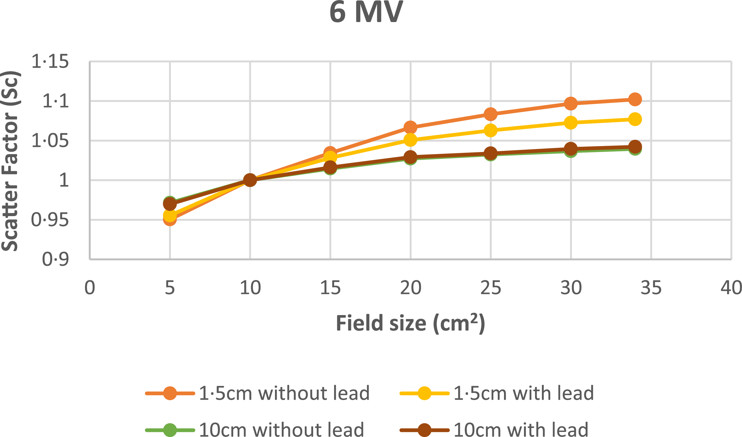
Figure 6 shows the head scatter factor for 6 MV photon beam in parallel orientation of different field sizes measured from 5 × 5 cm2 to 34 × 34 cm2 at dmax (1·5 cm) and 10 cm depths. A maximum deviation of 6% is observed for without lead at 1·5 cm and 10 cm depths. A maximum deviation of 0·3% is observed for with and without lead at 10 cm depths. A maximum deviation of 2·3% at 1·5 cm with and without lead indicates a reduction in electron contamination when lead is introduced.
Variation of Sc with field size at 1·5 cm and 10 cm depth using mini-phantom for 6 MV.

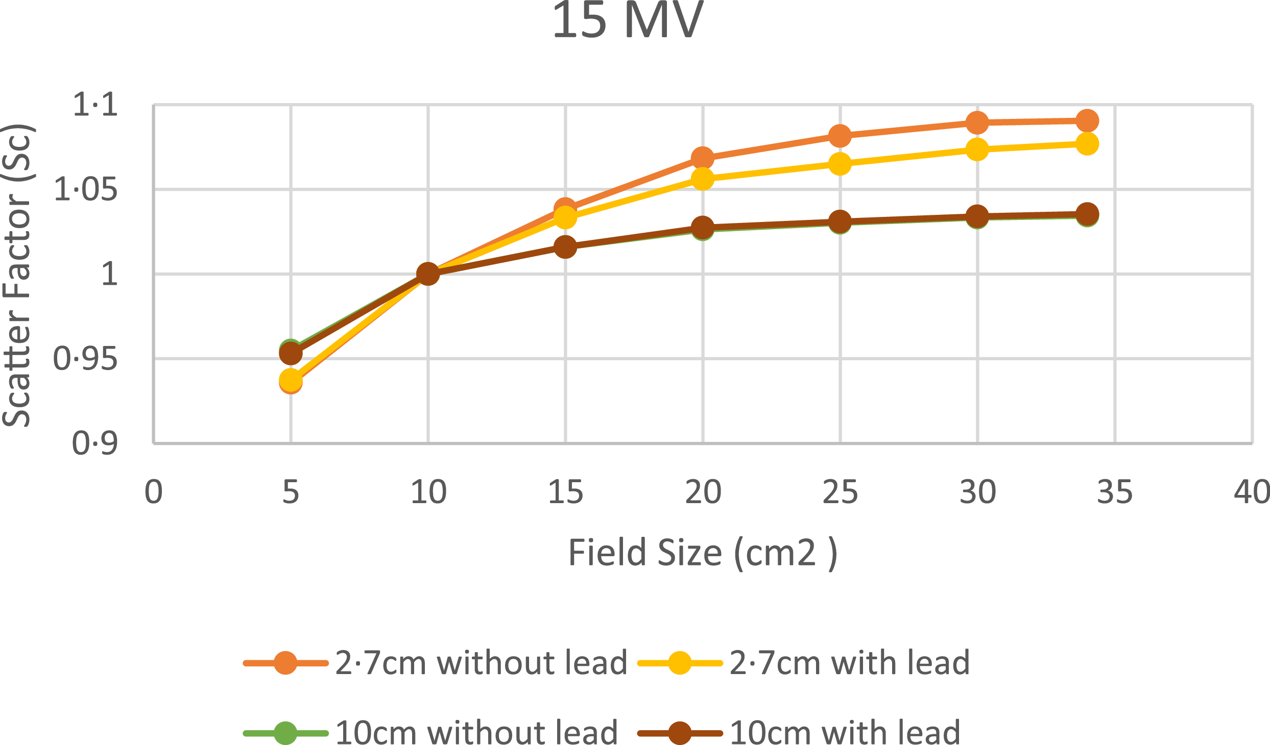
Figure 7 shows the head scatter factor for 15 MV photon beam in parallel orientation of different field sizes measured from 5 × 5 cm2 to 34 × 34 cm2 at dmax(2·7 cm) and 10 cm depths. A maximum deviation of 5·4% is observed for without lead at 2·7 cm and 10 cm depths. A maximum deviation of ±0·2% is observed for with and without lead at 10 cm depths. A maximum deviation of ±1·6% at 2·7 cm with and without lead indicates a reduction in electron contamination when lead is introduced.
Variation of Sc with field size at 2·7 cm and 10 cm depth using mini-phantom for 15 MV.

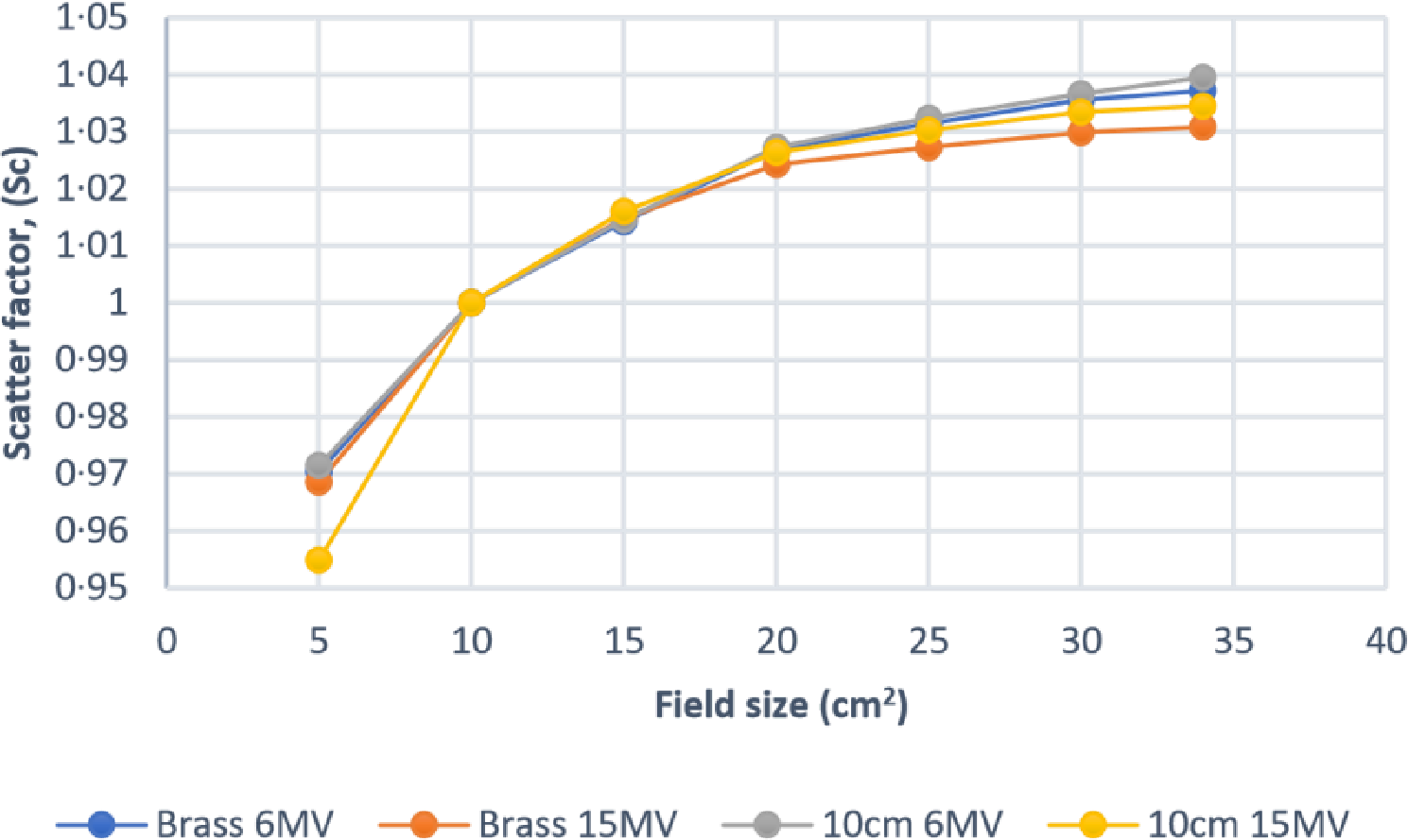
Figure 8 shows the head scatter measurements with brass buildup cap and mini-phantom at 10 cm depth for 6 MV and 15 MV photon beams. The maximum deviation is less than 2% in both the energies.
Variation of Sc with brass buildup and mini-phantom at 10 cm depth for 6 MV and 15 MV.

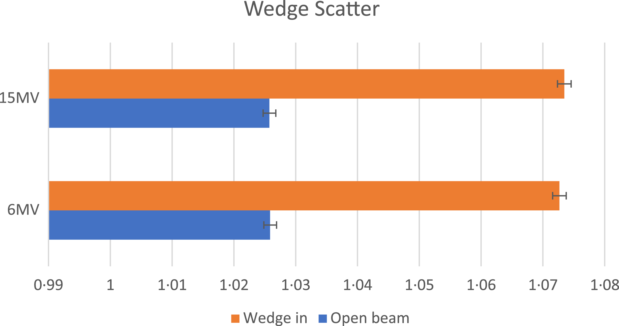
Figure 9 shows the effect of wedges on scatter factor for 6 MV and 15 MV. It is compared with the open fields, and a maximum deviation of 6·3% and 5·7% are observed between wedged and open fields for 6 MV and 15 MV beams, respectively, at larger field sizes.
Effects of wedges on scatter factor for 6 MV and 15 MV.

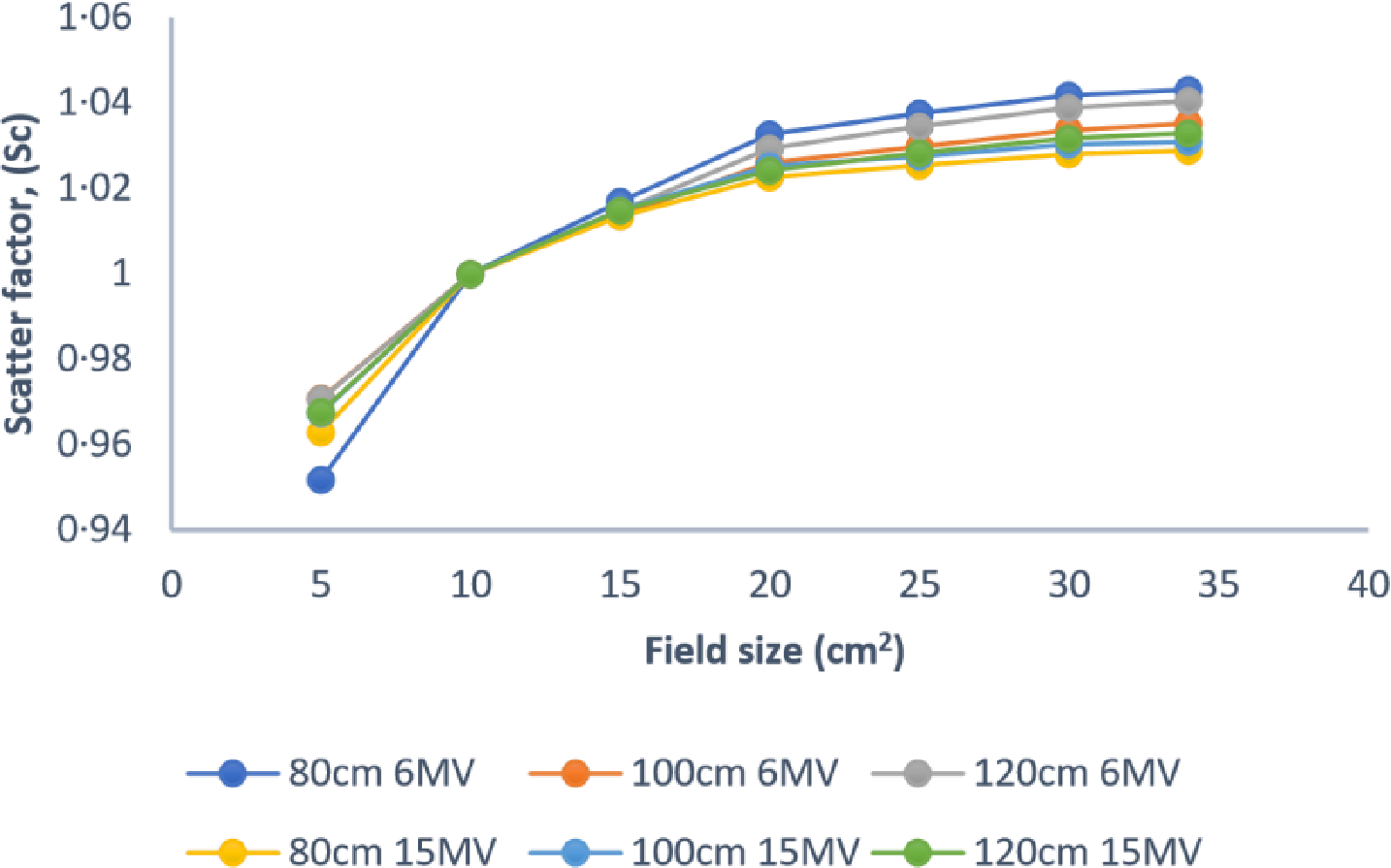
Figure 10 illustrates the variation of the scatter factor for different field sizes at various SSDs for 6 MV and 15 MV photon beams. The maximum deviation is less than 2% at different SSDs for both energies.
Variation of Sc with field sizes at various SSDs for 6 MV and 15 MV.

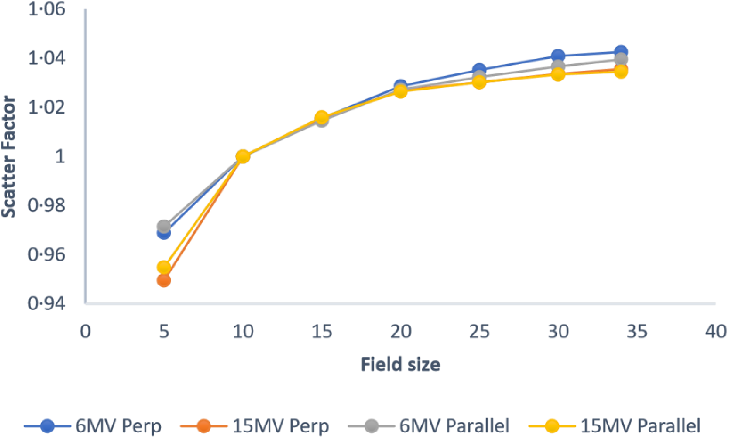
Figure 11 shows the deviation in scatter factor for parallel and perpendicular orientations for 6 MV and 15 MV photon beams. A maximum deviation of 0·4% and −0·5% was observed for the parallel and perpendicular orientations, respectively, for both energies.
Variation of Sc for parallel and perpendicular orientations for 6 MV and 15 MV.

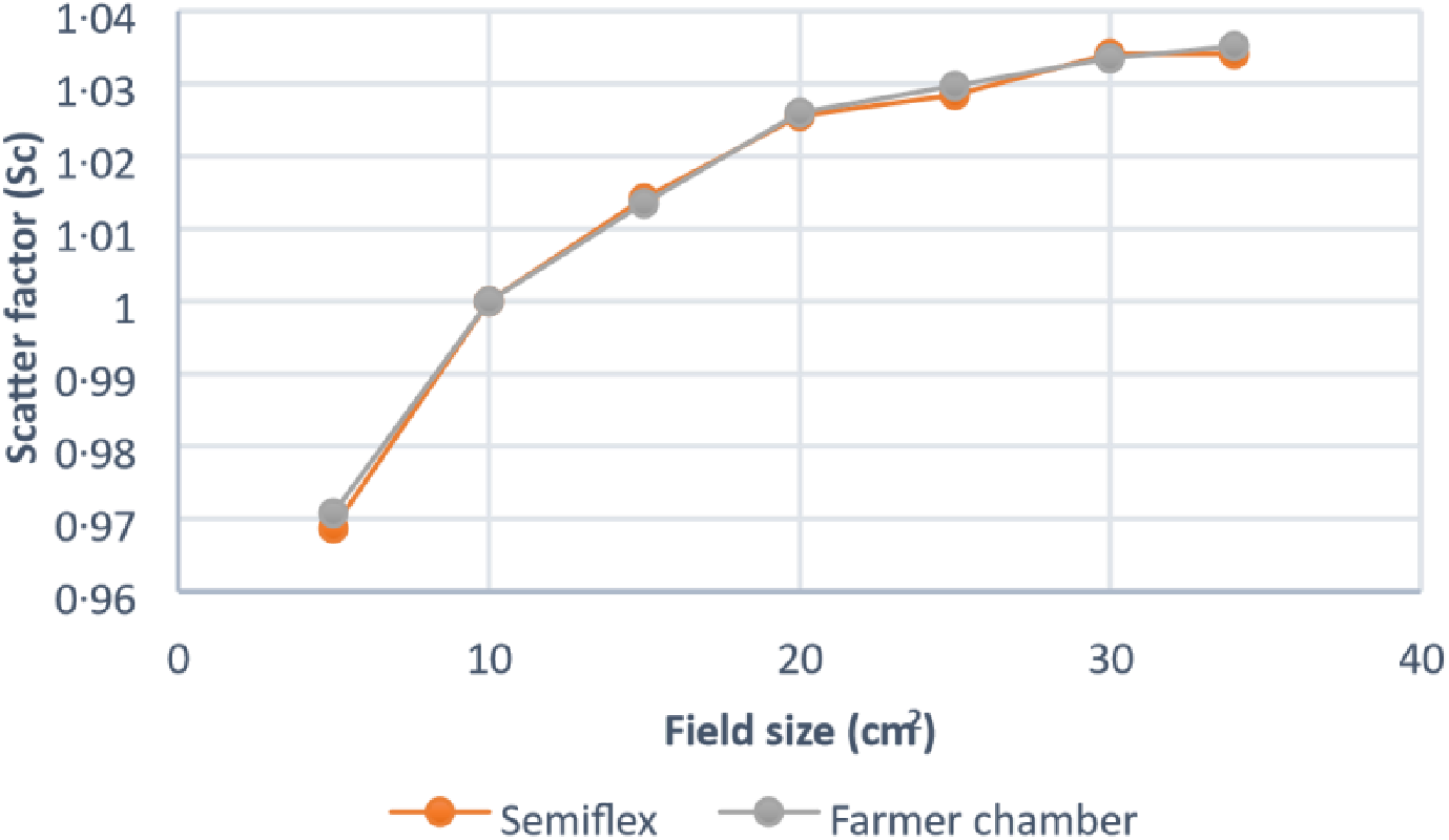
Figure 12 shows the comparison of scatter factor with two different volume chamber measurements. A maximum deviation of ±0·21% is observed between the two chambers.
Comparison of Sc with two different volume chambers.

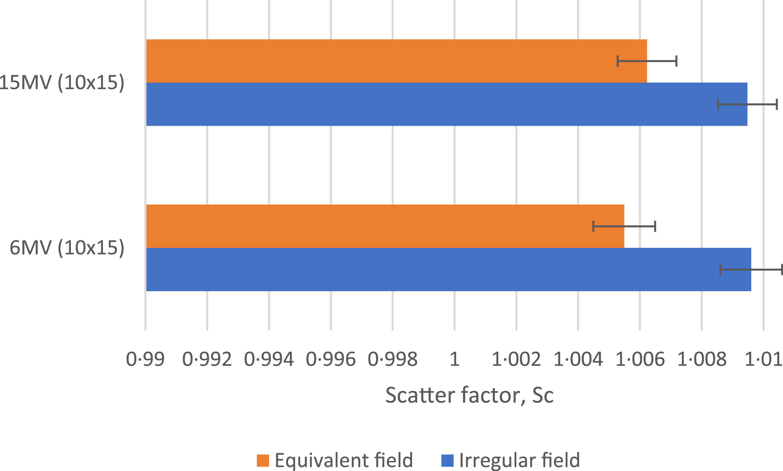
Figure 13 shows the variation of scatter factors for rectangular fields and equivalent square fields for 6 MV and 15 MV photon beams. A maximum deviation of −0·42% and −0·32% is observed between both the fields for 6 MV and 15 MV beams, respectively.
Variation of Sc for irregular fields and equivalent fields for 6 MV and 15 MV.

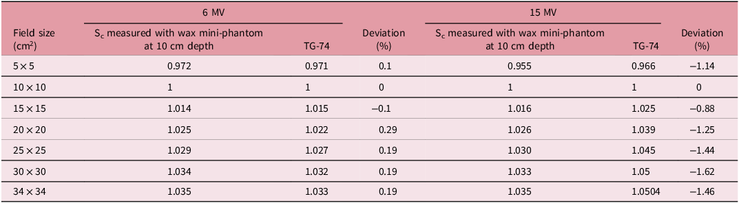
Table 1 shows the comparison of scatter factor measured for 6 MV and 15 MV using mini-phantom at 10 cm depths with the TG 74 recommendations. A maximum deviation of 0·3% and −1·5% are observed for 6 MV and 15 MV photon energies, respectively.
Comparison of measured Sc with TG-74 data at 10 cm depth

Table 1. Long description
A table comparing scatter factor measurements for 6 MV and 15 MV photon energies at 10 cm depth. The table has 8 rows and 7 columns. The columns are labeled as follows: Field size (cm^2), S_c measured with wax mini-phantom at 10 cm depth for 6 MV, TG-74 for 6 MV, Deviation (%) for 6 MV, S_c measured with wax mini-phantom at 10 cm depth for 15 MV, TG-74 for 15 MV, and Deviation (%) for 15 MV. The row labels are: 5x5, 10x10, 15x15, 20x20, 25x25, 30x30, and 34x34. Row 1: 5x5, 0.972, 0.971, 0.1, 0.955, 0.966, -1.14. Row 2: 10x10, 1, 1, 0, 1, 1, 0. Row 3: 15x15, 1.014, 1.015, -0.1, 1.016, 1.025, -0.88. Row 4: 20x20, 1.025, 1.022, 0.29, 1.026, 1.039, -1.25. Row 5: 25x25, 1.029, 1.027, 0.19, 1.030, 1.045, -1.44. Row 6: 30x30, 1.034, 1.032, 0.19, 1.033, 1.05, -1.62. Row 7: 34x34, 1.035, 1.033, 0.19, 1.035, 1.0504, -1.46.
Table 2 shows the dose prescription using two methodologies in Semiflex ionization chamber and Gafchromic film. The results indicated an underestimation of the dose when the calculations are based on the output factor.
Comparison of prescribed and delivered dose measured with Semiflex ionization chamber and Gafchromic film

Table 2. Long description
A table comparing prescribed and measured doses using two methodologies in Semiflex ionization chamber and Gafchromic film. The table has four rows and three columns. The columns are labeled Prescribed dose (cGy), Measured dose (cGy) MU calculated using output factor, Deviation (percent), MU calculated using S c and S p, and Deviation (percent). The rows are labeled Semiflex ionization chamber and Gafchromic film. Row 1: Prescribed dose (cGy), 200; Measured dose (cGy) MU calculated using output factor, 188 plus or minus 2; Deviation (percent), negative 6; MU calculated using S c and S p, 197 plus or minus 2; Deviation (percent), negative 0.5. Row 2: Prescribed dose (cGy), 200; Measured dose (cGy) MU calculated using output factor, 180 plus or minus 5; Deviation (percent), negative 7.5; MU calculated using S c and S p, 201 plus or minus 2; Deviation (percent), 1.5.
Discussion
The collimator scatter factor (Sc), also known as head scatter, which is usually measured in air with high-Z buildup caps or with a mini-phantom to eliminate phantom scatter (Sp) is an essential parameter in TPS beam modelling and MU calculations. Reference Appasamy, Xavier, Thayalan and Ramasubramanian2,Reference Zhu, Ahnesjö and Lam8 Sc is the contribution of extra-focal radiation from linear accelerator head components like the flattening filter, primary and secondary collimators, wedges and multileaf collimators (MLCs), etc. Reliable beam modelling in TPS algorithms and the separation of head and phantom scatter components in output factor calculations depend on accurate determination of Sc. In 3D conformal radiotherapy (3DCRT) breast treatments, where large field sizes are commonly used, variations in phantom scatter are relatively small compared to head scatter contributions. Reference Eid, Mohammed, Abdelaal and Taha4 Thus, precise measurement and modelling of Sc play a significant role in ensuring accurate dose calculation and MU determination for such clinical applications. Measurement of the collimator scatter factor (Sc) using traditional in-air techniques and ESTRO-recommended methods are still in the topic of ongoing interest, even though many modern TPSs employ relatively simple measurement of collimator scatter Sc in brass buildup. Reference Appasamy, Xavier, Thayalan and Ramasubramanian2,Reference Dutreix, Bridier, Bjärngard, Mijnheer, Shaw and Svensson3,Reference Zhu, Ahnesjö and Lam8 Several studies have examined both conventional brass buildup cap and mini-phantom techniques to obtain accurate estimates of collimator scatter, focusing on the practical challenges involved in separating this component. As described in AAPM TG-74, the measured dose consists of primary radiation, scattered radiation and electron contamination. Reference Zhu, Ahnesjö and Lam8 So, careful separation of the head scatter component is essential for reliable Sc determination. The influence of electron contamination, particularly for measurements performed near dmax or with inadequate buildup, remains an ongoing topic of discussion. Reference Venselaar, Heukelom and Jager7 Consequently, minimizing electron contamination is still considered a key requirement for accurate and clinically relevant collimator scatter measurements.
ESTRO recommends the use of a mini-phantom with a measurement depth of approximately 10 cm to effectively eliminate electron contamination in collimator scatter measurements. Reference Dutreix, Bridier, Bjärngard, Mijnheer, Shaw and Svensson3
Alternatively, sufficient brass buildup of appropriate thickness has also been shown to suppress contaminant electrons. Some authors have investigated the effect of electron contamination by measuring the percentage depth dose (PDD) in a mini-phantom and subtracting it from the PDD obtained in a full-scatter phantom, thereby isolating the photon scatter component. Reference Venselaar, Heukelom and Jager7 Traditionally, electron contamination is often minimized using a thin lead filter of approximately 1 mm thickness. Reference Almond, Biggs and Coursey1 In this work, a 1-mm-thick lead sheet was placed in the beam to eliminate electron contamination during collimator scatter factor measurements performed at dmax. A high atomic number lead sheet was used to remove electron contamination. This study evaluated 6 MV and 15 MV Sc for square, rectangular and wedged fields at different SSDs using both traditional and mini-phantom methods with different chambers and orientations.
Figures 6 and 7 show that the collimator scatter factor increases with field size and decreases with increasing photon energy, in agreement with published studies. Reference Appasamy, Xavier, Thayalan and Ramasubramanian2,Reference Zhu, Ahnesjö and Lam8 Higher Sc values at dmax compared with 10 cm depth are mainly due to electron contamination at shallow depths agreed with Appasamy et al. Reference Appasamy, Xavier, Thayalan and Ramasubramanian2 Measurements at 10 cm depth with and without the lead filter agreed well for 6 MV and 15 MV beams, indicating negligible electron contamination at this depth. In contrast, collimator scatters measured with and without lead at dmax shows deviation of 2·3% for 6 MV and ±1·6% for 15 MV photon beams, which indicates a reduction of contaminant electrons when lead is introduced. Since TPS beam modelling requires Sc at dmax, the present study shows that using a 1-mm lead sheet, with correction for its attenuation, provides a practical method for obtaining electron-uncontaminated collimator scatter factor at dmax. The lead-filtered dmax data still do not agree with the 10 cm depth measurements for several reasons. One key reason is that dmax is not constant with field size; as the field size decreases, dmax shifts closer to the surface. Reference Semwal9,Reference Sixel and Podgorsak10
Figure 8 shows good agreement between the brass buildup and mini-phantom measurements, indicating that this approach provides a simple and practical method for measuring the collimator scatter factor in air. As suggested by previous studies, Reference Appasamy, Xavier, Thayalan and Ramasubramanian2,Reference Dutreix, Bridier, Bjärngard, Mijnheer, Shaw and Svensson3 contaminant electron contributions can be effectively suppressed, allowing the measurements to represent only the photon fluence component of collimator scatter. The present study therefore recommends the use of an appropriate thickness of high-Z buildup material to achieve electronic equilibrium and eliminate electron contamination. The resulting data showed good agreement with measurements performed at 10 cm depth, in line with ESTRO guidelines. Reference Dutreix, Bridier, Bjärngard, Mijnheer, Shaw and Svensson3
Figure 9 illustrates that the collimator scatter factor varies significantly between open and wedged fields, with a deviation of 6·3% and 5·7% for 6 MV and 15 MV photon beams, respectively. This variation highlights the influence of wedge filters on scatter conditions. In TPS beam modelling and forward planning, wedge, collimator and phantom scatter factors are explicitly used for MU calculations. Reference Mehnati, Biglari and Jomehzadeh6 Several authors Reference Venselaar, Heukelom and Jager7 have reported that inaccuracies in wedge scatter factors can introduce MU calculation errors of up to 5%. The present study therefore emphasizes that wedge scatter factors should be measured separately for different field sizes and wedge settings to ensure accurate beam modelling and forward planning in clinical TPS use.
As reported by many authors, Reference Appasamy, Xavier, Thayalan and Ramasubramanian2,Reference Zhu, Ahnesjö and Lam8 SSD has no significant influence on the collimator scatter factor. The present results are consistent with these findings, with Sc values measured at SSDs of 80 cm, 100 cm and 120 cm differing by less than 2·0%. This confirms that Sc is essentially independent of SSD.
The two ionization chambers showed an insignificant deviation in the measured collimator scatter factor (Sc) when using an appropriate buildup cap or mini-phantom, with a maximum deviation of 0·2%. Likewise, variations in chamber orientation (parallel or perpendicular) resulted in negligible differences in Sc, remaining within ±0·5%. These observations are consistent with results reported by several authors, and comparable agreement was observed in the present study. Reference Appasamy, Xavier, Thayalan and Ramasubramanian2
The irregular field also showed an insignificant deviation in the measured collimator scatter factor when compared with the equivalent square field. Reference Appasamy, Xavier, Thayalan and Ramasubramanian2,Reference Zhu, Ahnesjö and Lam8 The observed data are in good agreement with results reported by several authors. In the present study, the contribution of MLC scatter was intentionally excluded. Accurate estimation of MLC scatter requires advanced dose calculation algorithms, such as Monte Carlo-based methods or other Type-B and Type-C algorithms, which are capable of modelling head scatter more precisely. Since such algorithms were beyond the scope of this study, MLC scatter was excluded from the study. Reference Eid, Mohammed, Abdelaal and Taha4
In accordance with low-Z material recommendations from ESTRO, wax was selected to design the mini-phantom which is simple and cost-effective for use in any clinic. The measured data are in good agreement with the AAPM TG-74 recommended values for 6 MV and 15 MV photon beams.
This work was further extended to forward planning for extracorporeal irradiation. A tibia bone substitute was fabricated using wax. Chamber and film measurements showed a 6 to 8% underestimation of dose when MUs were calculated using the output factor. These findings suggest that, for extracorporeal irradiation, forward planning MU calculations should incorporate separately measured Sc and sufficient phantom scatter factors to achieve accurate dose delivery.
An uncertainty analysis was performed to assess the reliability of the measurements. Repeated ionization chamber measurements (n = 3) showed a positional uncertainty of 0·0086, indicating good reproducibility. Similarly, Gafchromic film measurements (n = 3) yielded a statistical uncertainty of 0·00033 in net optical density, demonstrating minimal random variation. Film dosimetry introduces further uncertainties related to scanner response and calibration, generally within 2–3%. Positioning errors, particularly in mini-phantom measurements, may contribute additional variation due to alignment sensitivity. Despite these factors, the overall uncertainty remains within clinically acceptable limits, indicating that the observed variations in collimator scatter factors are primarily due to physical effects such as electron contamination and material properties rather than experimental limitations.
The collimator scatter measurements were performed using ionization chamber-based dosimetry in our study. In future work, these results will be validated through comparative measurements using additional dosimeters such as thermoluminescent dosimeters and optically stimulated luminescent dosimeters. Furthermore, the current study was restricted to regular field sizes; subsequent investigations will include irregular field configurations shaped using MLCs. These extensions are expected to enhance the accuracy and broader clinical applicability of collimator scatter factor evaluation.
Conclusion
A wax columnar mini-phantom was designed in accordance with ESTRO recommendations for the measurement of collimator scatter factor. The Sc was measured in a dual-energy linear accelerator. Measurements performed at dmax showed higher Sc values due to electron contamination. Sc measurement is therefore recommended using a suitable buildup cap/mini-phantom at 10 cm depth/a mini-phantom with a 1-mm lead sheet placed on the tray for measurements at dmax to eliminate electron contamination on Sc. No significant variation in Sc was observed with changes in SSD, detector type, chamber orientation or irregular field sizes for both 6 MV and 15 MV photon beams. In contrast, wedged fields demonstrated more deviation in Sc compared with open fields. This indicates that wedge-induced scatter should be appropriately accounted for TPS beam modelling and forward planning MU calculations. Furthermore, the use of accurately measured Sc, along with appropriate phantom scatter factors (Sp) or dedicated extracorporeal phantoms, is important to deliver accurate doses in extracorporeal irradiation where phantom scatters are minimal.
Acknowledgement
We are thankful to Dr N.G.P. Arts and Science College for great support.
Competing interests
No conflict.




 Open access

